



A Complete Guide to USB Protocol: Demystifying the Universal Serial Bus — From History and Architect
This article explains USB three-layer architecture, four endpoint transfer modes, descriptor types, six device states and full enumeration workflow for host-dev
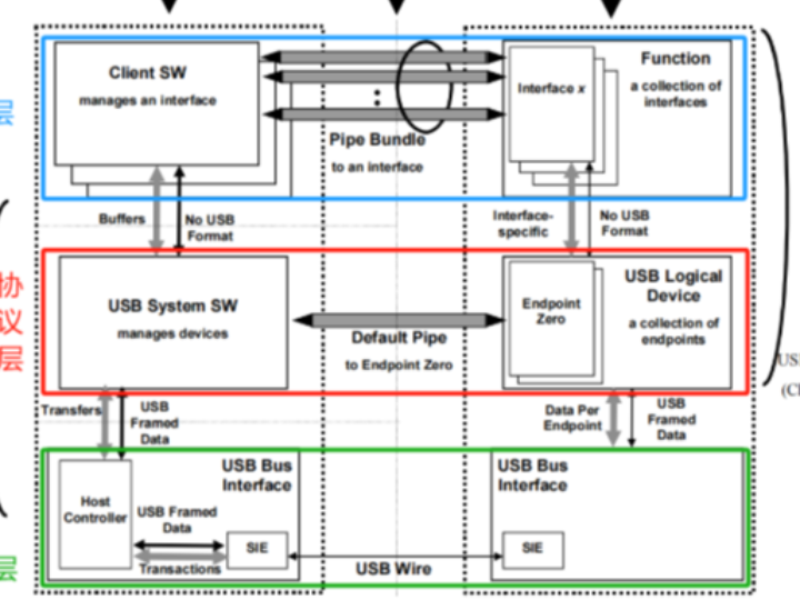
The USB protocol consists of multiple layers, mainly including the following layers:
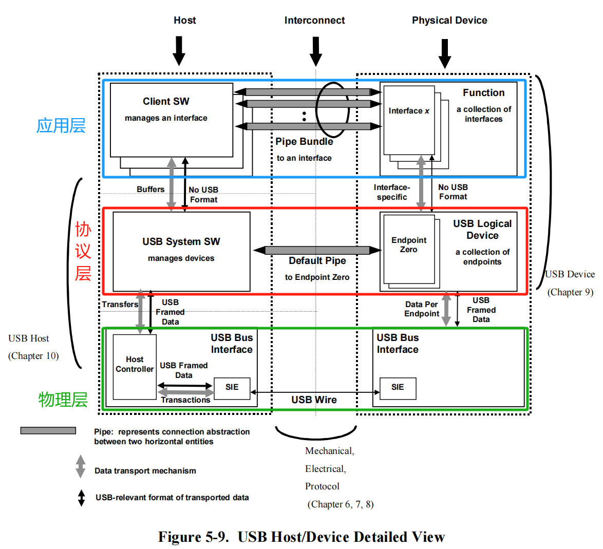
Among them, from the bottom layer to the top layer:
Application Layer (Function Layer):
This layer is responsible for implementing the application functions of USB devices
It defines the specific functions and behaviors of different types of devices (such as mice, keyboards, scanners, etc.)
It abstracts device functions into Interfaces. Users can directly access the function interfaces through drivers or client software (Client SW) to implement specific application needs, improving the scalability and interoperability of USB devices
Different interfaces can encapsulate different device functions, such as keyboards, mice, audio devices, etc. Users can choose the appropriate interface to access and use as needed
Protocol Layer (USB Device Layer):
This layer is responsible for the logical control and data transmission of USB devices. Client software (Client SW) converts its data send/receive requests and contents into USB transfer transactions through the protocol layer
It defines functions such as USB device enumeration, configuration, and endpoint management, as well as the implementation of different transfer types (control, bulk, interrupt, isochronous)
This layer provides a standardized USB device interface and shields the underlying physical details
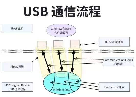
A USB device is composed of several endpoints (EndPoint); an endpoint is the smallest object of communication logic on a USB device
Each endpoint can be used for different data transfer purposes, such as control, interrupt, bulk, or isochronous transfers. Usually, a device has one control endpoint for transferring device configuration and status information, while other endpoints are used for sending and receiving data
The host's driver or user program establishes logical pipes (Pipe) with these endpoints and sends/receives data through the pipes. This forms independent data channels
Physical Layer (USB Bus Interface Layer):
This layer is responsible for the implementation of the USB physical interface, including basic functions such as electrical characteristics, connectors, and signal transmission
It defines the physical characteristics of the USB bus and is the foundation of USB communication
The host needs to continuously query (poll) the devices connected to the USB bus, discover new devices, and perform enumeration, configuration, and other operations. At the same time, it needs to schedule data transmission among multiple devices to ensure that each device can access the bus fairly
On the device side, it needs to identify and filter the data packets on the bus and route them to the corresponding endpoints. Different types of endpoints (control, interrupt, bulk, isochronous) have different transfer characteristic requirements
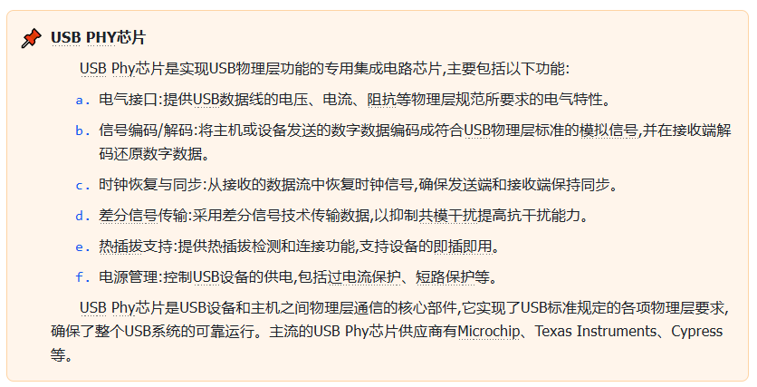
These complex low-level protocol interactions are handled by the operating system's USB driver and the device-side physical layer processing module (such as the PHY chip), and are transparent to upper-layer applications and drivers
These three layers have a clear division of labor and together form a complete USB communication system:
The physical layer provides the basic hardware interface
The protocol layer implements data transmission according to the USB protocol
The application layer implements specific functions for different device types
This layered design gives the USB system good scalability and portability. New devices only need to be developed at the application layer, without modifying the underlying physical and logical implementations.
2. USB Communication Endpoints and Endpoint Descriptors
The endpoint (Endpoint) is the most basic unit of communication between a USB device and the host. Each logical USB device consists of multiple independent endpoints:
Each endpoint is assigned a unique endpoint number when the device is designed, and there is no need to negotiate with the host when the device connects;
According to the data transfer direction, endpoints are divided into output endpoints (used to receive data from the host) and input endpoints (used to send data to the host). This classification is from the host's perspective;
An endpoint can only have a single transfer direction, which is determined when the device is designed;
When a USB device connects, it negotiates with the host to obtain an address. Through the device address, endpoint number, and transfer direction, an endpoint can be uniquely identified for communication.
In the USB protocol, endpoints have four transfer modes:
Bulk transfer:
Asynchronous transfer mode
No time limit
Can transfer data of any format and length
Used to transfer data that is not urgent but requires large bandwidth
Interrupt transfer:
Asynchronous transfer mode
Has a time limit
Small data volume transfer
Used to transfer data that requires timely response
Control transfer:
Asynchronous transfer mode
Has a time limit
Used for control operations such as device configuration and status query
Isochronous transfer:
Synchronous transfer mode
Has a time limit
Does not support retransmission on error
Used to transfer time-sensitive data that can tolerate packet loss, such as audio and video streams
Note that each USB device has a set of default endpoints working in control transfer mode, used to transfer configuration and control information. They are the output and input endpoints with endpoint number 0. When a USB device is just plugged in and has not been assigned an address, the host can only access endpoint 0 through bus address 0. At this time, the USB device's communication capability is limited. Only after the host obtains the device descriptors through endpoint 0 and completes the enumeration operation can the device communicate normally with the host.
Each endpoint has different working modes and limitations, and this information needs to be told to the host during device enumeration. The descriptor that describes the working modes and limitations of an endpoint is called the Endpoint Descriptor. It records the following key information about the endpoint:
Endpoint number
Endpoint polling frequency
Transfer mode (bulk, interrupt, isochronous, etc.)
Maximum packet length
Through the endpoint descriptor, the host can understand the specific characteristics of each endpoint, so as to communicate and exchange data with it correctly.
3. USB Enumeration Process, Descriptors, and USB Device States
When a USB device is plugged into the host, it needs to go through an enumeration process, which mainly includes the following steps:
After detecting a new USB device connection, the host queries the device's basic information, such as vendor ID and product ID
The device provides a series of device descriptors (Device Descriptor) to the host, describing its type, functions, endpoint information, etc.
Based on this descriptor information, the host confirms the device type and selects the appropriate USB device driver
The host also assigns an address to the device and configures it so that it enters the working state
Finally, applications can access the functions provided by the device by calling the operating system's USB driver interface
Each USB device has only one device descriptor (Device Descriptor). This descriptor defines information such as the USB version number used by the device, device class code, device subclass code, protocol code, vendor information, and the possible number of configurations. A USB device can have multiple configurations, but only one can be used at a time.
Each configuration of a USB device corresponds to a Configuration Descriptor, which defines information such as the device's power supply method and the number of supported interfaces. A USB device can support multiple interfaces. USB devices with multiple interfaces can be divided into two types:
USB Compound Device:
One physical USB device contains multiple function interfaces (Interface)
Each interface can be used independently; for example, an audio device contains interfaces such as audio control, audio streaming, and MIDI streaming
The host operating system manages and accesses each interface as an independent logical device
Compound devices need to provide complete descriptor information, including the descriptor of each interface
USB Composite Device:
Multiple physically independent USB devices (such as a keyboard and a mouse) are combined together and connected to the host as one integrated device
The host operating system manages the entire composite device as a single logical device
The descriptor information of a composite device is also integral and cannot be split into independent interfaces
The individual physical devices in a composite device are usually related and share some hardware resources
Taking the common USB compound device, the USB audio device, as an example, it usually contains the following interfaces:
Audio control interface - used for configuration and control of the audio device
Audio streaming interface - used to transmit PCM audio data
MIDI streaming interface - used to transmit MIDI protocol music data
In USB devices, the Interface Descriptor is used to describe interface information, including the following types:
Interface class, subclass, and protocol
Used to identify the function type of the interface, such as HID, audio, video, etc.
Endpoint information used by the interface
Describes the number of endpoints used by the interface, endpoint types (control, interrupt, bulk, isochronous), etc.
Interface number and settings
The interface number is used to identify the uniqueness of the interface
Interface settings describe different working configurations of the interface
Note that one interface may involve multiple endpoints, and each endpoint has an endpoint descriptor.
Above we mentioned interface types and subtypes. In fact, to facilitate the management and access of different kinds of USB devices, the USB protocol defines a series of device classes and subclasses. The main USB device types are as follows:
Human Interface Device (HID)
Includes input devices such as mice, keyboards, and game controllers
Uses the simple, standard HID protocol for data interaction
Mass Storage Class (MSC)
Includes storage devices such as USB flash drives and portable hard drives
Uses the mass storage device protocol for data transfer
Communication Device Class (CDC)
Includes communication devices such as USB serial ports and modems
Uses the communication device protocol for data exchange
Audio Class
Includes audio devices such as USB microphones and speakers
Uses the audio device protocol for data transfer
Video Class
Includes USB cameras and video capture devices
Uses the video device protocol for data transfer
Printer Class
Includes USB printers
Uses the printer device protocol for data exchange
Smart Card Class
Includes USB smart card readers
Uses the smart card device protocol for data transfer
The division of these classes is reflected in the class, subclass, and protocol related fields of the device descriptor and interface descriptor, mainly the interface descriptor:
Device class (Class)
Used to identify the broad type of the device, such as HID (human interface), CDC (communication device), Mass Storage, etc.
Subclass (SubClass)
Used to further subdivide the device type, such as mice, keyboards, and game controllers under the HID class
Protocol
Describes the specific protocol supported by the device, such as USB HID under the HID class and serial port protocol under the CDC class
The host selects the driver based on this device type information and the vendor information mentioned in the device descriptor.
The USB protocol specifies that USB devices have six working states:
Unconfigured State: this is the initial state when a USB device is just connected to the host. In this state, the device has not been assigned an address and cannot perform any communication
Address State: after the device is identified and assigned a unique address, it enters the address state. In this state, the device can communicate with the host using the assigned address
Configured State: when the device sends a configuration request to the host and the host accepts the request, the device enters the configured state. In this state, the device has completed all configuration processes, including setting endpoints and obtaining descriptors, and can begin data transfer with the host
Suspended State: when the device has no data transfer for a period of time, it automatically enters the suspended state to save power. In this state, the device's power is turned off; unless an interrupt event occurs, the device remains in the suspended state
Default State: the device is powered and the reset is complete, but no address has been assigned yet. The host can access the device through the default address 0 and assign an address
Powered State: the device is connected and receives power from the USB bus
These state transitions correspond to the USB device enumeration process. The host performs corresponding operations and configurations according to the device's current state until the device is fully initialized and ready:
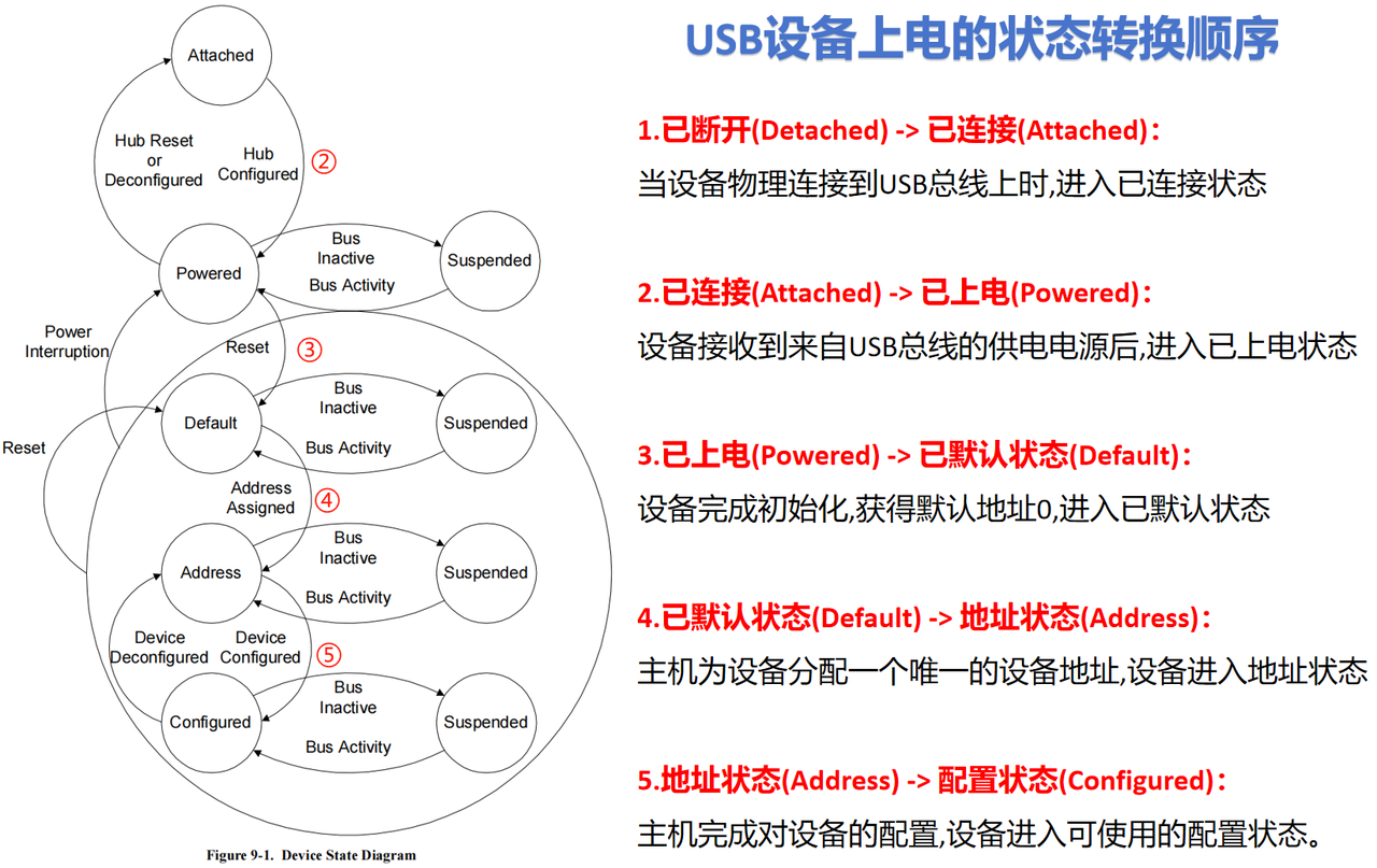
Note that if the device loses connection with the host in any state, it will return to the Detached state. This state transition mechanism ensures that USB devices can be safely plugged and unplugged and managed.
When we plug a USB device into an available port on a PC, the PC needs to go through a series of operations to assign an address to the device, negotiate and select a device driver, and perform necessary configuration on the USB device. This process is called the enumeration process, as follows:
Device connection detection
Due to the hot-plug design of USB connectors, plugging a USB device into a HUB port changes the HUB's connection state.
When the host queries the HUB, the HUB reports that a state change indicates the device is connected
At this time, the host learns the port where the newly inserted device is located
Port reset
The host waits at least 100ms until the device is fully inserted and the power supply is stable
The host sends commands to the HUB to enable and reset the port, making the device enter the Default state
The device draws no more than 100mA of current from the VBUS pin to complete basic functional configuration
The host can access the device through the default address 0
Get device descriptor
The host accesses the device through address 0 and communicates with the device's endpoint 0
Obtains device descriptor information
Select configuration
The host selects an appropriate configuration according to the device descriptor information
Assign address
The host assigns a unique device address to the device
Load driver
The host selects and loads the appropriate USB driver according to the device information
The device enters the Configured state
Set interface
The host performs initialization settings for each interface of the device
Device ready