
W55RP20-EVB-MKR Module MicroPython Practice (16): Modbus Industrial Protocol Communication
This article is the 16th part of the WIZnet W55RP20 chip MicroPython tutorial series, written based on the latest official firmware.
This article is the 16th part of the WIZnet W55RP20 chip MicroPython tutorial series, written based on the latest official firmware. All code has been practically verified and can be directly flashed and run. Copyright Notice: This article is an original technical article from WIZnet. Please indicate the source when reproducing.
Preface
In the previous practical tutorial, we completed the MQTT protocol and various cloud platform integration feature development for the W55RP20 chip, achieving remote device networking, cloud data upload, platform monitoring, and control.
In this article, we enter the core application of industrial automation — Modbus Industrial Protocol Communication.
Modbus is the most universal and stable standard communication protocol in the industrial field. Modbus TCP is implemented over Ethernet and is widely used in industrial devices such as PLCs, sensors, instruments, inverters, and servo controllers. The W55RP20, as a hardware TCP/IP protocol stack chip, is ideally suited for building a high-stability Modbus TCP Server (slave), which can be directly read and controlled by host computers, touch screens, and PLCs, enabling industrial data acquisition and remote control.
This tutorial implements a complete Modbus TCP Server based on MicroPython, supporting function codes 03/04/06/16, and can directly interface with industrial devices such as Modbus Poll, Kingview, ForceControl, Siemens/Mitsubishi PLCs, and more.
This article will guide you through:
Modbus TCP industrial protocol principles and message structure
Building a Modbus TCP Server (slave) with W55RP20
Holding register and input register simulation and management
Complete analysis and response for function codes 03/04/06/16
Industrial-grade exception code handling and communication stability assurance
Hardware protocol stack industrial communication anti-interference design
Standard Modbus integration solution for embedded industrial devices
Series Tutorial Learning Path
This column consists of 16 articles, progressively covering the full process of W55RP20-EVB-Pico module MicroPython development:
Part 1: Static IP Configuration and Network Basics
Part 2: DHCP Auto-Networking and Network Diagnostics
Part 3: TCP Client Communication
Part 4: TCP Server Communication
Part 5: UDP Unicast Data Communication
Part 6: UDP Multicast/Broadcast Data Communication
Part 7: DNS Domain Name Resolution
Part 8: NTP — Getting Time from the Network
Part 9: HTTP Client Requests
Part 10: HTTP Server Setup
Part 11: HTTP Protocol and OneNET Platform Cloud Data Upload
Part 12: MQTT Protocol Basic Communication Verification
Part 13: MQTT Protocol Integration with Alibaba Cloud Platform
Part 14: MQTT Protocol Integration with OneNET Platform
Part 15: MQTT Protocol Integration with ThingSpeak Platform
Part 16: Modbus Industrial Protocol Communication (This Article)
Table of Contents
2. Flashing W55RP20 Dedicated MicroPython Firmware
3. Hardware Connection and Development Environment Configuration
3.2 Thonny Development Environment Configuration
4. Modbus TCP Protocol Core Principles
5. WIZnet Hardware Protocol Stack Industrial Communication Advantages
7. Running Results and Test Verification
8. Common Issues One-Stop Troubleshooting
8.2 Port Identification Issues
9. Typical Application Scenarios
10. W55RP20 Core Advantages Comparison
12. Series Summary and Resource Access
1. Preparation
1.1 Software Preparation
All required software is available in free versions. Download and install as needed — no additional payment required.
| Software Name | Version Requirement | Download URL | Description |
|---|---|---|---|
| Thonny | 4.0 and above | Thonny Official Download | Lightweight MicroPython IDE, supporting code editing, flashing, and serial debugging |
| W55RP20-EVB-Pico Module MicroPython Firmware | Latest stable version | WIZnet Official Firmware Download | Custom-built for the W55RP20-EVB-Pico module, with integrated WIZnet hardware drivers, protocol stack, and HTTP library |
1.2 Hardware Preparation
As shown in the figure, the W55RP20-EVB-MKR development board physical image.
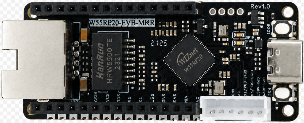
The following hardware is required:
W55RP20-EVB-MKR development board × 1
USB data cable × 1
Standard Ethernet cable × 1
Router or switch × 1
Note: The
W55RP20-EVB-MKRalready has an onboard Ethernet interface, requiring no additional soldering or wiring of other components — plug and play. This significantly reduces the probability of wiring errors and hardware failures.
2. Flashing W55RP20 Dedicated MicroPython Firmware
Before running the static IP example, you need to flash the corresponding MicroPython firmware onto the W55RP20-EVB-MKR first.
Firmware file example:
firmware.uf2The W55RP20-EVB-MKR is compatible with the Raspberry Pi Pico UF2 firmware flashing method. The steps are as follows:
Use a USB data cable to connect the development board and the computer
Hold down the BOOTSEL button on the development board
Press the RUN button once
Release the buttons after the computer recognizes the RPI-RP2 disk
Drag the .uf2 firmware file into the RPI-RP2 disk
The development board automatically restarts, and firmware flashing is complete
Note: If the computer does not recognize the
RPI-RP2disk, you can try unplugging and replugging the USB data cable, or replace it with a USB cable that supports data transmission.
3. Hardware Connection and Development Environment Configuration
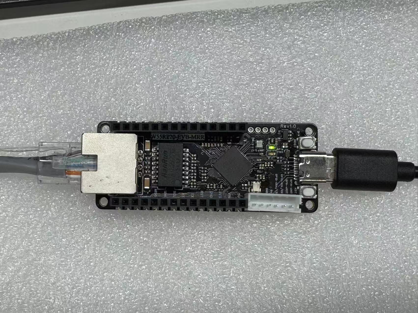
3.1 Hardware Connection
The W55RP20-EVB-MKR connection is extremely simple, requiring only two steps:
Use a USB data cable to connect the development board to the computer (for power supply, code flashing, and serial debugging)
Use an Ethernet cable to connect the development board's Ethernet interface to the router's LAN port
The following figure shows the hardware connection diagram
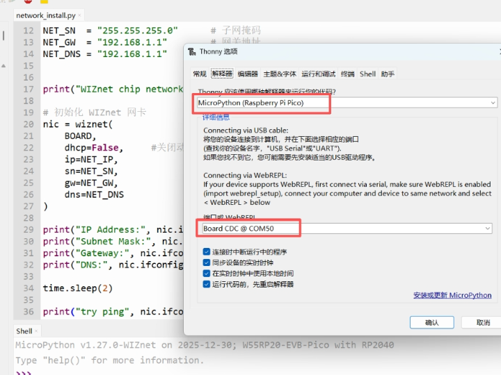
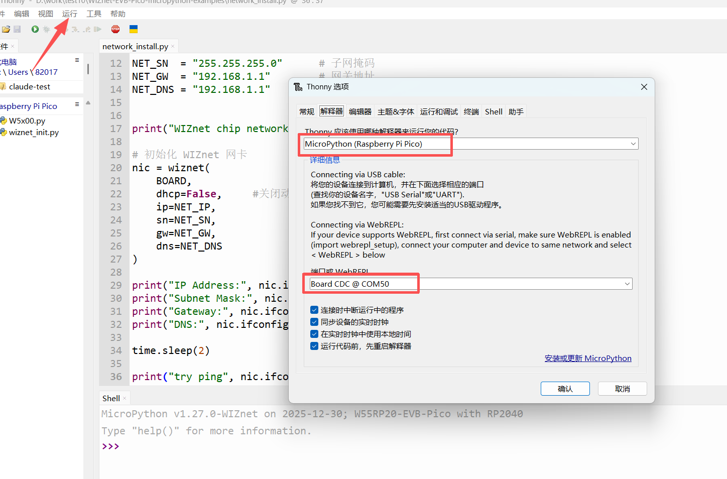
3.2 Thonny Development Environment Configuration
Open the Thonny software, click the top menu bar "Run" → "Configure Interpreter"
Switch to the "Interpreter" tab
Select "MicroPython (generic)" from the "Interpreter" dropdown list
Select the serial port corresponding to the W55RP20-EVB-MKR from the "Port" dropdown list (usually displayed as Board CDC @ COMx)
Click "OK" to complete the configuration
The interface after configuration is shown below:
If the development board does not appear in the port list, please try:
Unplugging and replugging the USB data cable
Replacing with a USB data cable that supports data transmission
Closing other software that occupies the serial port (such as serial assistants, Arduino IDE, etc.)
Re-flashing the MicroPython firmware
4. Modbus TCP Protocol Core Principles
4.1 Modbus TCP Introduction
Modbus TCP is an industrial Ethernet standard protocol that communicates over TCP port 502. Devices are divided into:
Server (slave): This device (providing register data)
Client (master): PLC / host computer / debugging software (initiates reads and writes)
4.2 Core Function Codes
03: Read Holding Registers
04: Read Input Registers
06: Write Single Holding Register
16: Write Multiple Holding Registers
4.3 Message Structure
MBAP Header (7 bytes): Transaction ID + Protocol ID + Length + Unit ID
PDU Data Body: Function Code + Data Content
4.4 Communication Flow
Device starts Modbus TCP Server, listening on port 502
Master station (computer / PLC) initiates TCP connection
Master station sends request message
Slave station parses function code and register address
Reads / writes register data
Slave station returns response message
Connection is maintained, supporting continuous communication
5. WIZnet Hardware Protocol Stack Industrial Communication Advantages
Compared to traditional software TCP solutions, the W5500 hardware protocol stack has extremely strong advantages in industrial Modbus scenarios:
Hardware natively handles TCP connections, 0% MCU utilization, without affecting real-time control; industrial-grade stability, 24/7 non-stop operation with no disconnections or packet loss; hardware automatically handles retransmission, flow control, and checksum, making communication more reliable; supports multiple Sockets, can simultaneously provide Modbus + cloud services; microsecond-level response speed, meeting industrial real-time requirements; strong anti-interference, no disconnections in complex factory environments.
6. Core Code Analysis
6.1 Complete Runnable Code
BOARD = "w55rp20-evb-pico"
USE_DHCP = False
# Static IP settings
NET_IP = "192.168.11.20"
NET_SN = "255.255.255.0"
NET_GW = "192.168.11.1"
NET_DNS = "8.8.8.8"
# Modbus TCP settings
SERVER_PORT = 502
UNIT_ID = 1
from usocket import socket, SOL_SOCKET, SO_REUSEADDR
import ustruct as struct
from wiznet_init import wiznet
# Register mapping (for Modbus Poll debugging)
HOLDING_REGISTERS = [0] * 32
INPUT_REGISTERS = [1000 + i for i in range(32)]
# Exception response
def _exception_response(transaction_id, unit_id, function_code, exception_code):
pdu = bytes([function_code | 0x80, exception_code])
mbap = struct.pack(">HHHB", transaction_id, 0, len(pdu) + 1, unit_id)
return mbap + pdu
# Normal response
def _normal_response(transaction_id, unit_id, pdu):
mbap = struct.pack(">HHHB", transaction_id, 0, len(pdu) + 1, unit_id)
return mbap + pdu
# Read registers
def _read_registers(registers, start_addr, quantity):
if quantity < 1 or quantity > 125:
return None, 3
if start_addr < 0 or start_addr + quantity > len(registers):
return None, 2
payload = bytearray()
payload.append(quantity * 2)
for value in registers[start_addr:start_addr + quantity]:
payload.extend(struct.pack(">H", value & 0xFFFF))
return payload, None
# Write single register
def _write_single_register(registers, reg_addr, reg_value):
if reg_addr < 0 or reg_addr >= len(registers):
return 2
registers[reg_addr] = reg_value & 0xFFFF
return None
# Write multiple registers
def _write_multiple_registers(registers, start_addr, quantity, values):
if quantity < 1 or quantity > 123:
return 3
if start_addr < 0 or start_addr + quantity > len(registers):
return 2
if len(values) != quantity:
return 3
for i, value in enumerate(values):
registers[start_addr + i] = value & 0xFFFF
return None
# Handle Modbus request
def handle_modbus_request(request):
if len(request) < 8:
return None
transaction_id, protocol_id, length, unit_id = struct.unpack(">HHHB", request[:7])
if protocol_id != 0:
return None
if unit_id != UNIT_ID:
return None
if len(request) < 7 + length - 1:
return None
pdu = request[7:7 + length - 1]
if len(pdu) < 1:
return None
function_code = pdu[0]
try:
# FC03 Read Holding Registers
if function_code == 3:
if len(pdu) != 5:
return _exception_response(transaction_id, unit_id, function_code, 3)
start_addr, quantity = struct.unpack(">HH", pdu[1:5])
data, exc = _read_registers(HOLDING_REGISTERS, start_addr, quantity)
if exc is not None:
return _exception_response(transaction_id, unit_id, function_code, exc)
print("FC03 read holding registers: start={}, qty={}, values={}".format(
start_addr, quantity, HOLDING_REGISTERS[start_addr:start_addr + quantity]
))
return _normal_response(transaction_id, unit_id, bytes([function_code]) + data)
# FC04 Read Input Registers
if function_code == 4:
if len(pdu) != 5:
return _exception_response(transaction_id, unit_id, function_code, 3)
start_addr, quantity = struct.unpack(">HH", pdu[1:5])
data, exc = _read_registers(INPUT_REGISTERS, start_addr, quantity)
if exc is not None:
return _exception_response(transaction_id, unit_id, function_code, exc)
print("FC04 read input registers: start={}, qty={}, values={}".format(
start_addr, quantity, INPUT_REGISTERS[start_addr:start_addr + quantity]
))
return _normal_response(transaction_id, unit_id, bytes([function_code]) + data)
# FC06 Write Single Register
if function_code == 6:
if len(pdu) != 5:
return _exception_response(transaction_id, unit_id, function_code, 3)
reg_addr, reg_value = struct.unpack(">HH", pdu[1:5])
exc = _write_single_register(HOLDING_REGISTERS, reg_addr, reg_value)
if exc is not None:
return _exception_response(transaction_id, unit_id, function_code, exc)
print("FC06 write single register: addr={}, value={}".format(
reg_addr, HOLDING_REGISTERS[reg_addr]
))
return _normal_response(transaction_id, unit_id, pdu)
# FC16 Write Multiple Registers
if function_code == 16:
if len(pdu) < 6:
return _exception_response(transaction_id, unit_id, function_code, 3)
start_addr, quantity, byte_count = struct.unpack(">HHB", pdu[1:6])
data = pdu[6:]
if byte_count != len(data) or byte_count != quantity * 2:
return _exception_response(transaction_id, unit_id, function_code, 3)
values = []
for i in range(quantity):
values.append(struct.unpack(">H", data[i * 2:(i * 2) + 2])[0])
exc = _write_multiple_registers(HOLDING_REGISTERS, start_addr, quantity, values)
if exc is not None:
return _exception_response(transaction_id, unit_id, function_code, exc)
print("FC16 write multiple registers: start={}, qty={}, values={}".format(
start_addr, quantity, HOLDING_REGISTERS[start_addr:start_addr + quantity]
))
response_pdu = struct.pack(">BHH", function_code, start_addr, quantity)
return _normal_response(transaction_id, unit_id, response_pdu)
return _exception_response(transaction_id, unit_id, function_code, 1)
except Exception as e:
print("Request handling error:", e)
return _exception_response(transaction_id, unit_id, function_code, 4)
# Handle client connection
def serve_client(conn, addr):
print("Client connected:", addr)
try:
while True:
request = conn.recv(260)
if not request:
print("Client disconnected")
break
response = handle_modbus_request(request)
if response:
conn.send(response)
except Exception as e:
print("Client error:", e)
finally:
try:
conn.close()
except Exception:
pass
def main():
if USE_DHCP:
nic = wiznet(BOARD, dhcp=True)
else:
nic = wiznet(BOARD, dhcp=False, ip=NET_IP, sn=NET_SN, gw=NET_GW, dns=NET_DNS)
print("Modbus TCP server IP:", nic.ifconfig()[0])
print("Unit ID:", UNIT_ID)
print("Holding registers[0:8]:", HOLDING_REGISTERS[:8])
print("Input registers[0:8]:", INPUT_REGISTERS[:8])
s = socket()
try:
s.setsockopt(SOL_SOCKET, SO_REUSEADDR, 1)
except Exception:
pass
s.bind((nic.ifconfig()[0], SERVER_PORT))
s.listen(1)
print("Modbus TCP server listening on {}:{}".format(nic.ifconfig()[0], SERVER_PORT))
while True:
conn, addr = s.accept()
serve_client(conn, addr)
if __name__ == "__main__":
main()6.2 Code Feature Description
Supports static IP / DHCP dual-mode switching, adaptable for industrial field deployment;
Standard Modbus TCP port 502, compatible with all industrial master station devices;
Implements 32 holding registers + 32 input registers, can directly interface with SCADA software;
Fully supports the four core function codes FC03/04/06/16;
Built-in industrial-standard exception responses (address error, data error, function code error);
Hardware protocol stack handles TCP connections, stable communication with no latency; real-time printing of communication logs for easy debugging and fault localization; supports long connections and multi-packet continuous communication, meeting industrial automation requirements.
7. Running Results and Test Verification
After flashing the code into the device, the serial output is as follows:
MPY: soft reboot
Waiting for the network to connect ...
Waiting for the network to connect ...
MAC Address: 02:90:86:88:4d:56
IP Address: ('192.168.11.20', '255.255.255.0', '192.168.11.1', '8.8.8.8')
Modbus TCP server IP: 192.168.11.20
Unit ID: 1
Holding registers[0:8]: [0, 0, 0, 0, 0, 0, 0, 0]
Input registers [0:8]: [1000, 1001, 1002, 1003, 1004, 1005, 1006, 1007]
Modbus TCP server listening on 192.168.11.20:502
Connect using Modbus Poll:
IP: 192.168.11.20
Port: 502
ID: 1
Function codes: 03/04/06/16
Achievable results:
Successfully read holding registers and input registers
Successfully write single / multiple registers
Real-time read/write log printing on serial port
No errors, no packet loss, stable communication
Demo Video (Screen Recording 2026-04-30 110449 — Modbus Poll connection test)
8. Common Issues One-Stop Troubleshooting
8.1 Flashing Related Issues
| Issue Symptom | Troubleshooting Steps |
|---|---|
| Computer cannot recognize RPI-RP2 USB drive | 1. Confirm holding BOOTSEL button before plugging in USB; 2. Replace with a USB data cable that supports data transmission; 3. Change to a different USB port on the computer (prefer USB 2.0 ports); 4. Try using a different computer. |
| Development board has no response after dragging firmware | 1. Confirm that the W55RP20 dedicated firmware was downloaded, not the generic Raspberry Pi Pico firmware; 2. Re-flash the firmware; 3. Check if USB power supply is stable. |
8.2 Port Identification Issues
| Issue Symptom | Troubleshooting Steps |
|---|---|
| Cannot find development board port in Thonny | 1. Unplug and replug the USB data cable; 2. Close other software that occupies the serial port; 3. Check in Device Manager if there is a Board CDC device; 4. Re-flash the firmware; 5. Install the Raspberry Pi Pico USB driver. |
8.3 Other Common Issues
| Issue Symptom | Troubleshooting Steps |
|---|---|
| Modbus Poll connection failed | 1. Check that the device IP and computer are on the same subnet; 2. Turn off the computer firewall; 3. Confirm the device is listening on port 502; 4. Restart the device and debugging software. |
| Exception code 02 reported | 1. Register address out of range; 2. Addresses start from 0, do not fill in addresses that are too large. |
| Exception code 03 reported | 1. Read length exceeds the limit (maximum 125); 2. Write quantity does not comply with specifications. |
| Communication interrupted / unstable | 1. With the hardware protocol stack, disconnections are unlikely — this is usually an Ethernet cable / switch issue; 2. Replace the Ethernet cable and try replugging. |
8.4 Supplementary Issues
| Issue Symptom | Troubleshooting Steps |
|---|---|
| Thonny cannot recognize the development board | 1. Replace the USB cable; 2. Install the Pico serial driver; 3. Close software that occupies the serial port. |
9. Typical Application Scenarios
Industrial sensor data acquisition (temperature and humidity, pressure, flow rate);
PLC slave station module expansion; touch screen / SCADA software data monitoring;
Industrial equipment remote control and parameter configuration; factory automation production line data exchange;
Modbus gateway, data acquisition module, remote I/O module development.
10. W55RP20 Core Advantages Comparison
To give you a more intuitive understanding of the W55RP20's value, we compared the three mainstream embedded Ethernet solutions currently available:
| Comparison Dimension | W55RP20 Integrated Solution | External PHY Chip Solution | External Serial-to-Ethernet Module Solution |
|---|---|---|---|
| BOM Cost | Low (single chip) | Medium-High (MCU + module + peripheral components) | High |
| PCB Area | Small (only Ethernet port circuitry needed) | Large (need to reserve chip and routing space) | High |
| Development Difficulty | Low (one line of code to connect to network) | Medium-High (debug protocol stack, write drivers) | Low |
| Network Stability | Extremely High (WIZnet has focused on hardware TCP/IP protocol stack for 25 years) | Variable (requires high expertise from R&D personnel, must be proficient in protocol stack and network development to debug stably) | Variable (depends on the R&D company's capability level) |
| CPU Resource Utilization | 0% (protocol stack network processing entirely handled by hardware) | Over 50% (protocol stack runs entirely on MCU, occupying related resources) | 0% |
| Hardware Socket Count | 8 independent hardware Sockets | Depends on MCU capability, theoretically supports multi-channel expansion | Generally single-channel transparent transmission |
| Network Throughput | Up to 15Mbps | Depends on MCU capability | Approximately 3-5Mbps |
| Interface Ease of Use | Single-chip integration | MCU needs MII/RMII or similar interfaces | TTL interface |
| Deployment Difficulty | Low (mature MicroPython firmware, most application-layer protocols have library files available, can be flexibly added and deployed) | High (application-layer protocols require manual porting of open-source libraries for adaptation) | Depends on module integration; features without integration require self-encapsulation and parsing |
The W55RP20-EVB-MKR development board already has an onboard Ethernet interface, making it very suitable for beginners to quickly complete Ethernet function verification.
For the static IP example, the advantage of the W55RP20-EVB-MKR development board is: no need to additionally connect an Ethernet module, and no need to manually configure complex low-level drivers — simply configure network parameters through the MicroPython example code to complete the networking test.
11. Summary
This article detailed the complete process of implementing Modbus TCP industrial protocol communication on the W55RP20-EVB-MKR development board using MicroPython. From firmware flashing, hardware connection, and development environment configuration, to the core code implementation for Modbus TCP server setup and register read/write operations, to running result verification with Modbus Poll and common issue troubleshooting, we completed the Modbus industrial communication setup step by step.
Through this article, you should have mastered:
How to flash the dedicated MicroPython firmware for the W55RP20-EVB-MKR
Modbus TCP protocol basic working principles (function codes, message structure, communication flow)
Using MicroPython to implement a Modbus TCP server supporting multiple function codes (read/write holding registers, read input registers)
Verifying whether Modbus communication is successful through Modbus Poll debugging tool and serial output
Troubleshooting methods for common Modbus communication issues (flashing, port identification, register operations, etc.)
The W55RP20 chip, with its integrated Ethernet MAC+PHY and hardware TCP/IP protocol stack, demonstrates significant advantages in industrial communication. Whether as an industrial data acquisition gateway, PLC slave station module, or Modbus gateway device, it can achieve stable and reliable industrial-grade Ethernet communication at extremely low cost — the hardware protocol stack ensures zero CPU occupation and extremely high network stability, making it the best choice for smart hardware, industrial IoT, and edge data acquisition.
This article is the final installment of the W55RP20-EVB-MKR Module MicroPython Practice series. All 16 articles in this series have been completed, covering: basic networking → time synchronization → HTTP services → cloud platform integration → MQTT IoT → Modbus industrial control. The W55RP20 hardware protocol stack can simultaneously achieve IoT + industrial network dual-network convergence.
12. Series Summary and Resource Access
12.1 Series Summary
All 16 articles in this series have been completed, covering: basic networking → time synchronization → HTTP services → cloud platform integration → MQTT IoT → Modbus industrial control. The W55RP20 hardware protocol stack can simultaneously achieve IoT + industrial network dual-network convergence, making it the best choice for smart hardware, industrial IoT, and edge data acquisition.
12.2 Resource Access
Complete code for this article: WIZnet Official Gitee Repository
W55RP20 chip manual: WIZnet Official Documentation Website