
W55MH32 monitors light intensity in real time through SMTP protocol to provide high light intensity
W55MH32 monitors light intensity in real time through SMTP protocol to provide high light intensity alarm
1 Introduction
SMTP (Simple Mail Transfer Protocol) is a communications protocol used for email transmission. It is one of the standard Internet protocols designed specifically for sending and routing email. SMTP defines how email is sent from a sender to a recipient's email server and regulates email relay operations between servers.
The W55MH32 is WIZnet's new high-performance Ethernet MCU. It utilizes a high-performance Arm® Cortex-M3 core with a maximum clock speed of 216MHz, along with 1024KB of internal Flash and 96KB of internal SRAM. Notably, it features the WIZnet TCP/IP Offload Engine (TOE), integrating a full hardware TCP/IP stack, MAC, and PHY. It also features a 32KB independent Ethernet transmit and receive buffer for eight hardware sockets, making it a true all-in-one solution.
2 Project Environment
2.1 Hardware Preparation
- W55MH32 module
- Photoresistor sensor
- 1.44-inch TFT display
- One Ethernet cable
- Several DuPont cables
- Switch or router
2.2 Software Environment
- Example link: SMTP
- FreeAT_2.0.0.exe
- Keil5
3 Application Scenarios
3.1 Smart Agriculture and Greenhouse Monitoring
Pain Points: Light intensity in greenhouses is crucial for crop growth. Excessive light can burn seedlings, while insufficient light can impair photosynthesis. Traditional methods rely on manual, scheduled inspections, which are inefficient and unable to respond promptly to sudden weather changes.
Our Solution: Deploy the system in the greenhouse to set optimal light thresholds for crops. When the afternoon sun is too strong during a sunny summer day, or when continuous cloudy days cause insufficient light, the system immediately sends an alert to the farmer's mobile phone or email address. Administrators can promptly activate awnings or supplemental lighting to create an optimal growing environment for crops, ensuring yield and quality.
3.2 Management of light-sensitive areas in laboratories and precision instrument workshops
Pain Points: Certain precision chemical and optical experiments, or semiconductor manufacturing processes, must be conducted in strict darkrooms or under specific lighting conditions. Accidental light leakage can cause an entire batch of experiments to fail or even scrap the product, resulting in significant financial losses.
Our Solution: Deploy this system in areas requiring absolute light protection or constant lighting. As a reliable technical safeguard, if inadvertent light intrusion due to access control errors occurs, the system immediately notifies laboratory managers or shop floor engineers, enabling swift remedial action and minimizing losses.
3.3 Linkage between smart home and smart curtains
Pain Points: Users want to maintain comfortable indoor lighting while avoiding western exposure that can degrade furniture or overheat the room. Traditional curtains require manual opening and closing and don't automatically adjust based on real-time light levels.
Our Solution: The system serves as a "light sensing hub" for smart homes. In addition to email alerts, the W55MH32's powerful processing power allows it to be expanded into a coordinated control center. When the system detects excessive western exposure in the afternoon, it can send a notification ("The living room is currently too bright") or automatically close the smart curtain motors directly via Ethernet, creating a truly comfortable, energy-efficient, and intelligent living experience.
4 NetEase Mailbox (126/163): Obtaining the Authorization Code
Due to NetEase restrictions, third-party email clients must use an authorization code to log in to NetEase mailboxes. Log in to mail.126.com (163 mailbox: mail.163.com) via a browser and click "Settings" >> "POP3/SMTP/IMAP".
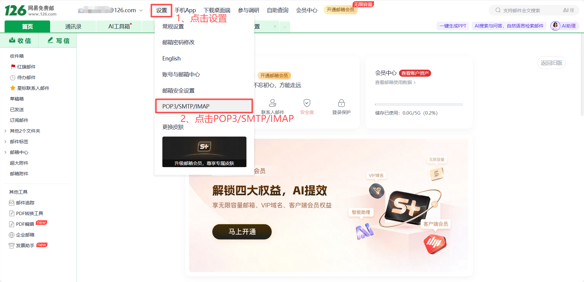
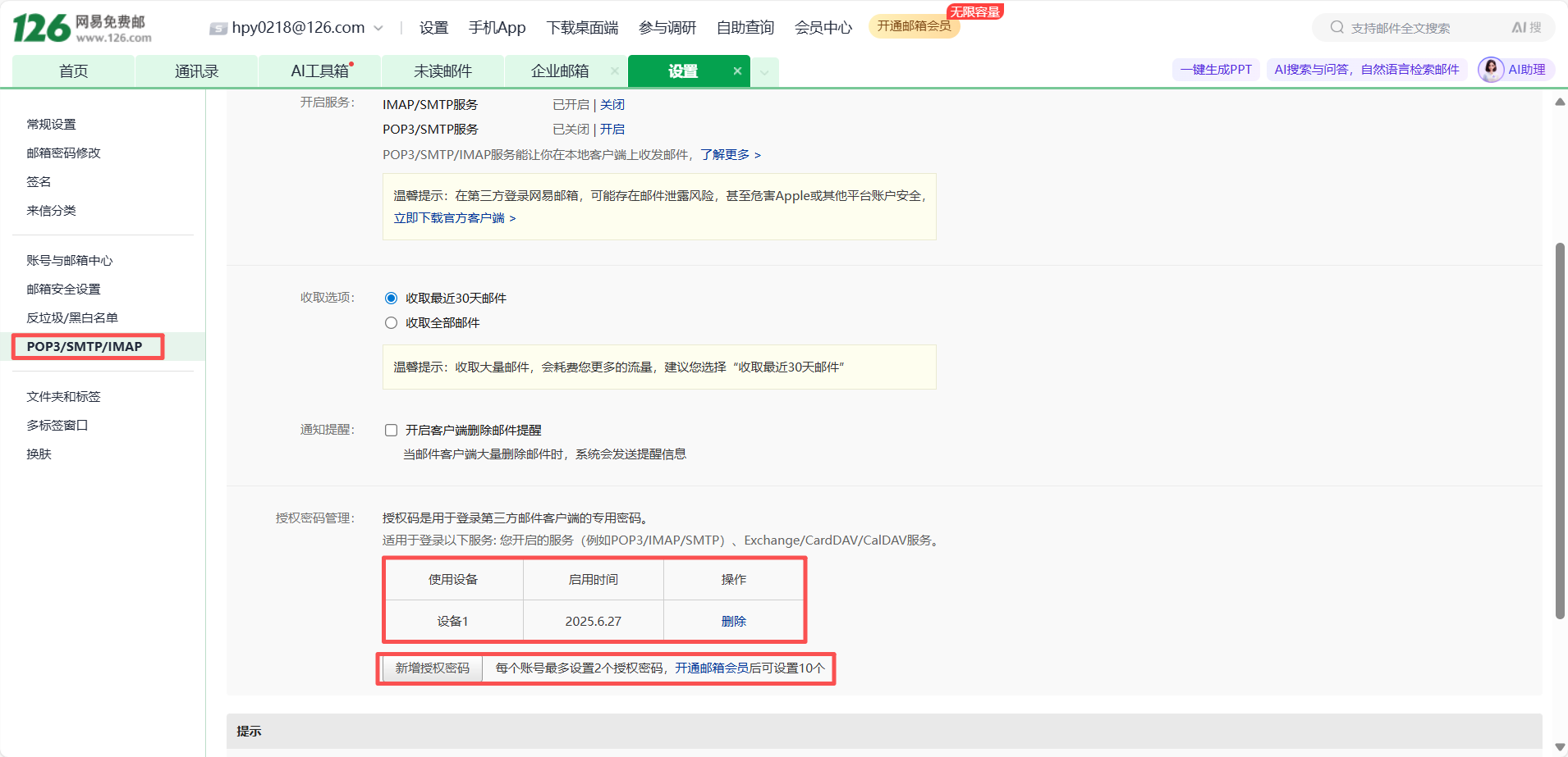
On the right web page, select "Enable" (IMAP/SMTP service), and the "Account Security Verification" page will pop up. Complete the verification yourself and obtain the client authorization password after verification.
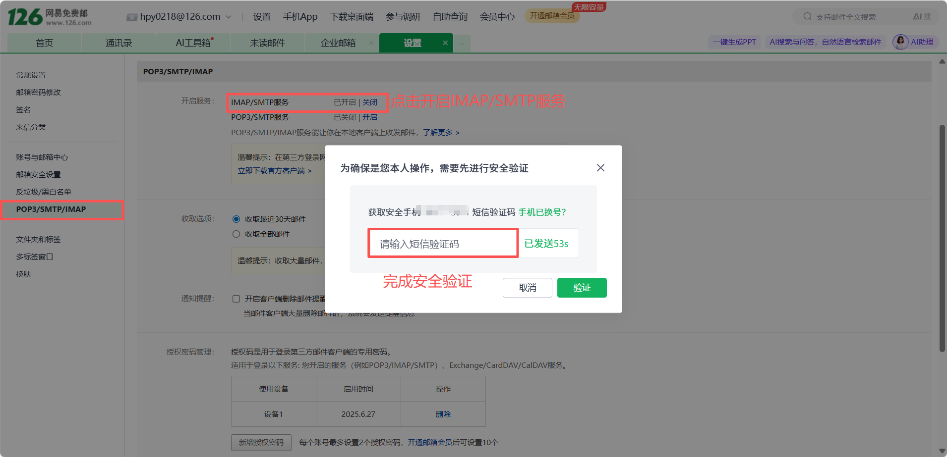
Multiple client authorization passwords can be managed here.
5. Code Modification
This article uses SMTP as an example:
Find the smtp.c file and change it to your own email account and authorization code.
char hello[50] = "HELO localhost"; // Identity command
char hello_reply[] = "250 OK"; // Id successfully responded
char AUTH[50] = "AUTH LOGIN"; // Authentication request
char AUTH_reply[] = "334 dXNlcm5hbWU6"; // The authentication request was successfully sent
char name_126[100] = "hpy0218@126.com"; // 126 Login email address wiznethk
char base64name_126[200]; // 126 base64 encoding of the login mailbox name
char name_reply[] = "334 UGFzc3dvcmQ6"; // The login name was sent successfully
char password_126[50] = "SAQ***Cnm5hi"; // 126 Email login password ZPURADLGRUPQLVBK
char base64password_126[100]; // base64 123 Password for logging in to the mailbox
char password_reply[] = "235 Authentication successful"; // Login successful response
char from[] = "h**0218@126.com"; // Sender email
char from_reply[] = "250 Mail OK";
char to[] = "1759***@qq.com"; // Recipient email address
char to_reply[] = "250 Mail OK";
char data_init[10] = "data"; // Request data transfer
char data_reply[] = "354"; // The request was successfully responded to HEAD
char Cc[] = ""; // Cc to email
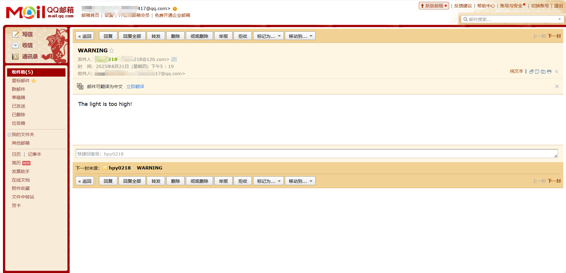
char subject[] = "WARNING"; // subject
char content[] = "The light is too high!"; // text part
char mime_reply[] = "250 Mail OK queued as"; // The email was sent successfully
char mailfrom[50] = "MAIL FROM:<>";
char rcptto[50] = "rcpt to:<>";
char mime[200] = "From:\r\n";
char mime1[50] = "To:\r\n";
char mime2[50] = "Cc:\r\n";
char mime3[50] = "Subject:\r\n";
char mime4[50] = "MIME-Version:1.0\r\nContent-Type:text/plain\r\n\r\n";
char mime5[50] = "\r\n.\r\n";Where from[] is the account number, password_126[50] is the authorization code, to[] is the email address to receive the email, subject[] is the subject of the email, and content[] is the content of the email.
The next step is to initialize the email content. The content of the mailmessage() function is as follows:
void mailmessage(void)
{
   uint16_t len_from = strlen(from);
   uint16_t len_to   = strlen(to);
   uint16_t len_Cc   = strlen(Cc);
   uint16_t len_sub  = strlen(subject);
   strcat(hello, "\r\n");
   strcat(AUTH, "\r\n");
   base64encode(name_126, base64name_126);
   base64encode(password_126, base64password_126);
   strcat(base64name_126, "\r\n");
   strcat(base64password_126, "\r\n");
   str_insert(mailfrom, from, 11);
   strcat(mailfrom, "\r\n");
   str_insert(rcptto, to, 9);
   strcat(rcptto, "\r\n");
   strcat(data_init, "\r\n");

   str_insert(mime, from, 5);
   str_insert(mime1, to, 3);
   str_insert(mime2, Cc, 3);
   str_insert(mime3, subject, 8);
   str_insert(mime5, content, 0);
   strcat(mime, mime1);
   strcat(mime, mime2);
   strcat(mime, mime3);
   strcat(mime, mime4);
   strcat(mime, mime5);
}
Send email data: Send email data in the following format:
Sender: From:
Recipient: To:
Cc:
Subject: Subject:
Email content: The actual text
End of data is indicated by \r\n\r\n
Wait for the server to return a 250 error, confirming that the email content has been successfully queued.
Next, we'll initialize the photoresistor sensor. To obtain the value of the photoresistor sensor, we first need to initialize the ADC.
/**
 * @brief  ADC Initialization Program
 * @param
 * @retval
 */
void ADCx_Init(void)
{
    //Turn on the ADC clock
    RCC_APB2PeriphClockCmd(ADC_CLK, ENABLE);

    //ADC frequency is divided by 6
    RCC_ADCCLKConfig(RCC_PCLK2_Div6);

    //Configure ADC structure
    ADC_InitTypeDef ADC_InitStructure;
    ADC_InitStructure.ADC_Mode = ADC_Mode_Independent;    //Standalone mode
    ADC_InitStructure.ADC_DataAlign = ADC_DataAlign_Right;    //Right-align data
    ADC_InitStructure.ADC_ExternalTrigConv = ADC_ExternalTrigConv_None;    //Software trigger
    ADC_InitStructure.ADC_ContinuousConvMode = DISABLE;    //Single conversion
    ADC_InitStructure.ADC_ScanConvMode = DISABLE;    //Non-scanning mode
    ADC_InitStructure.ADC_NbrOfChannel = 1;    //Total number of channels
    ADC_Init(ADCx, &ADC_InitStructure);    //Initialize ADC1

    //Turn on ADCx
    ADC_Cmd(ADCx, ENABLE);

    //Perform ADC calibration
    ADC_ResetCalibration(ADCx);
    while(ADC_GetResetCalibrationStatus(ADCx) == SET);
    ADC_StartCalibration(ADCx);
    while(ADC_GetCalibrationStatus(ADCx) == SET);
}

/**
 * @brief  Get the data after ADC conversion
 * @param  ADC_Channel     Select the ADC channel to be collected
 * @param  ADC_SampleTime  Select the required sampling time
 * @retval Returns the converted analog signal value
 */
u16 ADC_GetValue(uint8_t ADC_Channel,uint8_t ADC_SampleTime)
{
    //Configuring ADC channels
    ADC_RegularChannelConfig(ADCx, ADC_Channel, 1, ADC_SampleTime);

    ADC_SoftwareStartConvCmd(ADCx, ENABLE); //Software triggers ADC conversion
    while(ADC_GetFlagStatus(ADCx, ADC_FLAG_EOC) == RESET); //Read ADC conversion completion flag
    return ADC_GetConversionValue(ADCx);
}
After the ADC initialization is completed, the value of the photoresistor sensor can be obtained.
void LDR_Init(void)
{
    GPIO_InitTypeDef GPIO_InitStructure;

    RCC_APB2PeriphClockCmd (LDR_GPIO_CLK, ENABLE );    // Turn on the ADC IO port clock
    GPIO_InitStructure.GPIO_Pin = LDR_GPIO_PIN;                    // Configure ADC IO pin mode
    GPIO_InitStructure.GPIO_Mode = GPIO_Mode_AIN;        // Set as analog input

    GPIO_Init(LDR_GPIO_PORT, &GPIO_InitStructure);                //Initialize ADC IO

    ADCx_Init();

}

uint16_t LDR_ADC_Read(void)
{
    //Set the specified ADC rule group channel and sampling time
    return ADC_GetValue(ADC_CHANNEL, ADC_SampleTime_55Cycles5);
}

uint16_t LDR_Average_Data(void)
{
    uint32_t  tempData = 0;
    for (uint8_t i = 0; i < LDR_READ_TIMES; i++)
    {
        tempData += LDR_ADC_Read();
        delay_ms(5);
    }

    tempData /= LDR_READ_TIMES;
    return (uint16_t)tempData;
}

uint16_t LDR_LuxData()
{
    float voltage = 0;
    float R = 0;
    uint16_t Lux = 0;
    voltage = LDR_Average_Data();
    voltage  = voltage / 4096 * 3.3f;

    R = voltage / (3.3f - voltage) * 10000;

    Lux = 40000 * pow(R, -0.6021);

    if (Lux > 999)
    {
        Lux = 999;
    }
    return Lux;
}
We can also display the current light level in real time on the LCD screen.
Finally, add initialization to the main function and add the function inside the while function.
LDR_Init();
LCD_Init();//LCD Initialization
LCD_Fill(0,0,LCD_W,LCD_H,WHITE);
LCD_ShowString(32,32,(u8 *)"light",BLACK,WHITE,16,0);
while(1)
{
light = LDR_LuxData();
LCD_ShowIntNum(48,48,light,3,BLACK,WHITE,16);
if(light>900)
{
do_smtp(SOCKET_ID, ethernet_buf, smtp_server_ip); // smtp run
}
}
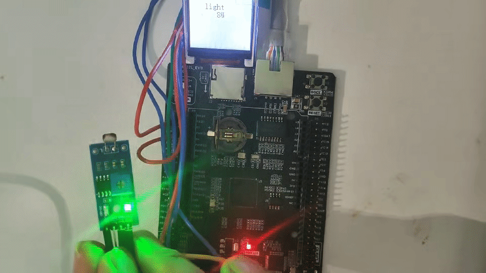
6 Functional Verification
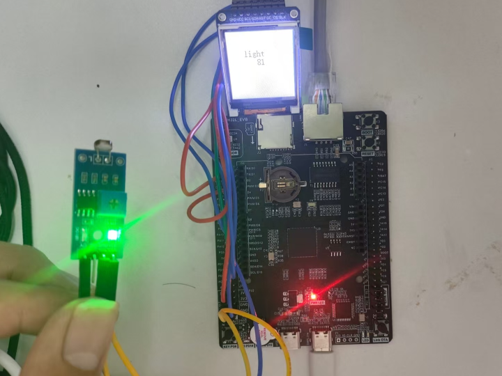
The program is burned and the hardware connections are complete as shown below:
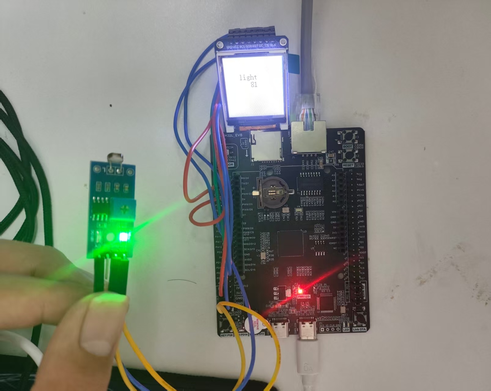
After the hardware is connected, power on and the serial assistant will print the following information:
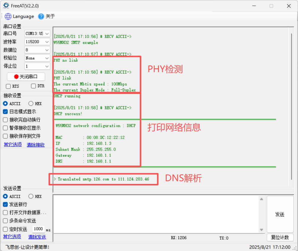
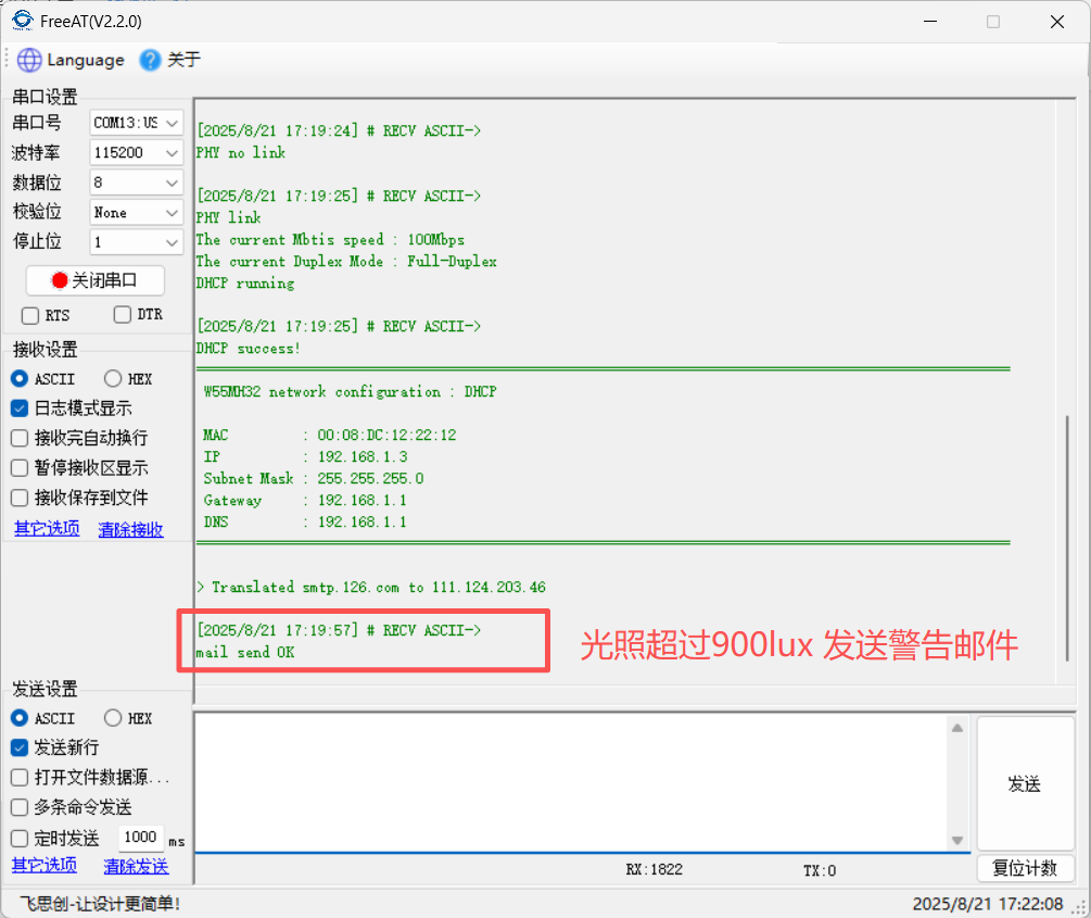
After successful power-on initialization, when the light intensity is detected, the light value is obtained through analysis and displayed on the TFT screen in real time. When the light intensity exceeds 900, a warning email of excessive light intensity will be sent to the designated receiving mailbox.
7 Summary
This project successfully implemented real-time light intensity monitoring and alarming using the W55MH32 via the SMTP protocol, validating the implementation of the Ethernet-based SMTP protocol. Thank you for your patience in reading! If you have any questions or would like to learn more about this product and its applications, please feel free to leave a message via private message or in the comments section. We will respond as soon as possible and provide more detailed answers and assistance!
————————————————
Copyright Notice: This article is original and is licensed under the CC 4.0 BY-SA license. Please include the original source link and this notice when reposting.
Original Link: https://blog.csdn.net/2301_81684513/article/details/150847557