
W55MH32-Infrared Remote Control Gateway
Infrared Remote Control Gateway: IRext Infrared Code Library + Remote Control of Infrared Air Conditioner Switches + Infrared Learning
1. Introduction
As smart homes move from concept to reality, the "smart transformation" of traditional infrared devices has become a pain point for many households. Infrared protocols for air conditioners vary widely across brands, making unified control difficult even with a mountain of remote controls. While there are many smart control apps on the market, these require network connectivity on the device side, something older air conditioners and other devices often lack. A remote-control-like product that can remotely control most air conditioner brands and supports infrared learning would solve this problem. Because WiFi signals are easily affected and communication power consumption is relatively high, I use Ethernet for communication. I previously used WIZnet chips for Ethernet functionality in a project, and they recently released the W55MH32 Ethernet chip with an MCU. I contacted them and requested a development board. My plan is to use a mini-program as the control side and the development board as the device side, communicating via Ethernet. The learned infrared codes will be stored locally on the device side using a w25q64 memory card.
The development board is currently working well. This chip integrates a full hardware TCP/IP protocol stack, MAC, and PHY. A network transformer and network port are also integrated into the development board. The Flash and SRAM are also ample. For those unfamiliar with network protocols, you can check out the example code on their official website. It also includes instructions on how to configure Keil and flash the code. The documentation is quite extensive.
Currently, the air conditioner can be remotely controlled, but the infrared learning mechanism is triggered by external infrared signals and printed over the serial port. The infrared learning functionality is not yet fully implemented. In the future, we will be able to trigger infrared learning through buttons in the mini-program, and be able to issue commands for control. Undocumented infrared codes will be stored locally using the w25q64 and FatFs file systems. Furthermore, I will later design the schematics and PCB myself, integrate all the hardware onto the board, and make the code, schematics, and PCBs available as open source.
2. Infrared
Infrared remote control code is a control code based on 38000Hz or 56000Hz carrier frequency. The receiver identifies the code by identifying the time interval with or without the carrier.
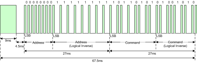
In the control layer, a sequence of high and low physical level pairs is usually used to represent an independent control signal, such as the following NEC code:
It uses a 9000us carrier + 4500us no-carrier time sequence to represent the pilot code, a 500us carrier + 500us no-carrier time sequence to represent logic 0, and a 500us carrier + 1500us no-carrier time sequence to represent logic 1. It is composed of a 2-byte address code and a 2-byte command code, and the full code time sequence length is 67.5ms.
IRext infrared library porting
IRext is an open-source universal infrared remote control code library, codec compression algorithms, and free peripheral services. It provides smart home developers with:
- Supports remote control of over 1,000 brands and tens of thousands of home appliance models across 16 categories.
- A universal infrared code library, both online and offline, includes a brand-categorized index and remote control codes.
- Flexible service deployment: Leverage open-source server and console code to quickly build your own code library service in a container environment in just 5 minutes.
- The code library and decoding algorithm are extremely compressed, allowing them to be stored and run on demanding hardware environments as low as a 51-inch MCU.
- Comprehensive platform compatibility and sample code are available.
- Comprehensive documentation covers every step of universal remote control development.
- Developers can use the code library extension tool to extend the library and freely modify solution functionality based on the open-source code.
Download the offline code library and IRext decoding library from the IRext official website. Place the IRext decoding library in your MCU project directory and modify the header file directory to include the decoding library header files. Download the required brand infrared code library from the offline code library using the brand index library provided by IRext. It can be stored in the MCU FLASH or on a server. The IRext decoding library supports decoding from the file system or from memory.
Decoding from the file system
ir_file_open(category, sub_category, "my_ir_code_file.bin");
ir_decode(key_code, user_data, ac_status, change_wind_dir);
ir_close();
Load into memory and decode
ir_binary_open(category, sub_category, buffer, buffer_length);
ir_decode(key_code, user_data, &ac_status, change_wind_dir);
ir_close();
After decoding, the decoded_data is used to generate an output IR time series. This series can be passed to the IR device driver to implement infrared transmission. However, the IRext library currently only supports the following functions: on/off, fan speed, temperature control, and fan sweep.
3.程序功能实现
Mini Programs and Device Communication Functions
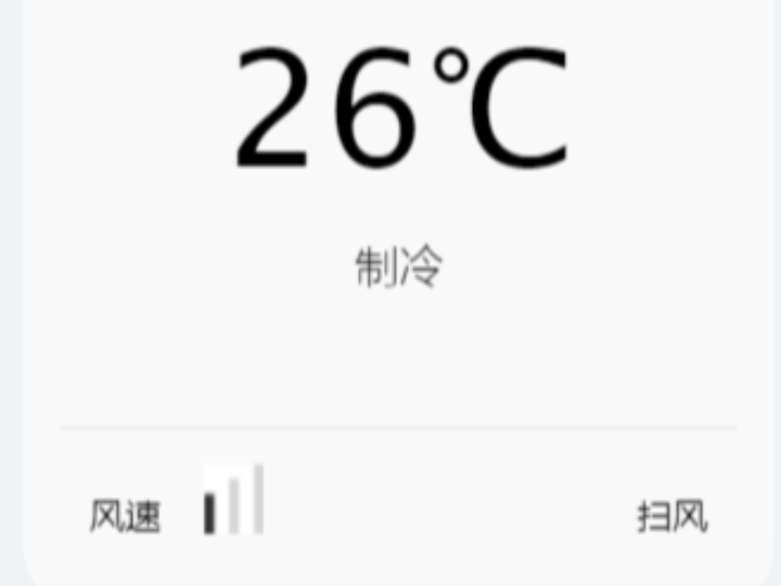
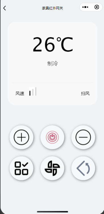
Using mini programs, you can remotely turn on the air conditioner without being physically present. Mini programs don't require downloading or installation; they can be accessed directly through platforms like WeChat. Therefore, I chose the WeChat mini program as the control terminal. The following is an image of the mini program interface:
The mini-program communicates with the device by calling the HTTP interface provided by the OneNET platform to transmit device attributes. The cloud platform then sends the data to the device via the MQTT protocol. The data format for interaction between the mini-program, the cloud platform, and the device is as follows: Command is used to issue control or infrared learning commands.
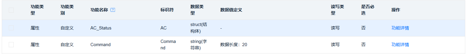
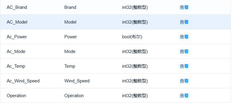
AC_Status is a structure that stores the status of the air conditioner. The specific contents are as follows: the structure members are the brand, model, power supply, mode, temperature, fan speed, and operation of the air conditioner. The operation must be defined because the IRext library needs to pass it as a parameter during decoding. This operation corresponds to the button pressed on the mini program end, such as power on/off, temperature increase, etc.
On the device side, I used the OneNET platform's communication topics: $sys/{pid}/{device-name}/thing/property/set for subscription and receiving control commands; and $sys/{pid}/{device-name}/thing/property/set_reply for responding to control commands. Other communication topics were not used. Interested parties can visit the OneNET MQTT communication topic for more information.
The mini program uses the HTTP interface provided by the OneNET platform. Specifically, the interface used is https://iot-api.heclouds.com/thingmodel/set-device-property . This interface is used to send device property setting commands to the device, which then returns the setting results. Other HTTP interfaces can access the OneNET HTTP interface.
In addition, before initiating an HTTPS request, you must include the unified security authentication information "authorization" in the headers to successfully request the interface. For details on how to do this, see Security Authentication.
We wrote the code using the development kit provided by the W55MH32, which includes some dependent header files and packages.
Copy the do_mqtt.c and do_mqtt.h files from the development kit into the project and modify the parameters in mqtt_params to specify the MQTT address and other parameters you want to connect to.
The do_mqtt() function is a state-machine-based MQTT client handler responsible for managing MQTT connections, subscriptions, keepalives, and message reception. When the function runs for the first time, it reaches conn and begins establishing a connection with the MQTT server. It then determines the state based on the status, entering the SUB topic subscription or KEEPALIVE keepalive state. If the state is ERR, it means an error has occurred in the MQTT connection. In the ERR state, you can reconnect or customize some other actions. Since I don't need to publish messages in the MQTT state machine, I deleted the publish message node. The code is as follows:
void do_mqtt(void)
{
   uint8_t ret;
   switch (run_status)
   {
   case CONN:
   {
       ret = MQTTConnect(&c, &data); /* Connecting to an MQTT server */
       printf("Connect to the MQTT server: %d.%d.%d.%d:%d\r\n", mqtt_params.server_ip[0], mqtt_params.server_ip[1], mqtt_params.server_ip[2], mqtt_params.server_ip[3], mqtt_params.port);
       printf("Connected:%s\r\n\r\n", ret == SUCCESSS ? "success" : "failed");
       if (ret != SUCCESSS)
       {
           run_status = ERR;
       }
       else
       {
           run_status = SUB;
       }
       break;
   }
   case SUB:
   {
       ret = MQTTSubscribe(&c, mqtt_params.subtopic, mqtt_params.subQoS, message_Arrived); /* Subscribe to a topic */
       printf("Subscribing to %s\r\n", mqtt_params.subtopic);
       printf("Subscribed:%s\r\n\r\n", ret == SUCCESSS ? "success" : "failed");
       if (ret != SUCCESSS)
       {
           run_status = ERR;
       }
       else
       {
           run_status = KEEPALIVE;
       }
       break;
   }
   case KEEPALIVE:
   {
       if (MQTTYield(&c, 30) != SUCCESSS) /* KEEPALIVE MQTT */
       {
           run_status = ERR;
       }
       delay_ms(100);
   }
   case RECV:
   {
       if (mqtt_recv_flag)
       {
           mqtt_recv_flag = 0;
           json_decode(mqtt_recv_msg);
       }
       delay_ms(100);
       break;
   }
   case ERR: /* Error Handling */
       printf("system ERROR!");
       delay_ms(1000);
       break;
   default:
       break;
   }
}
The messageArrived function is a callback function that is called when a message arrives from a topic we subscribe to. When a message arrives, this function is triggered and the message content is passed to this function as a parameter. Some parameters such as the topic, message content, and QOS level will be printed here. The code is as follows:
void message_Arrived(MessageData *md)
{
char topicname[64] = {0};
char msg[512] = {0};
sprintf(topicname, "%.*s", (int)md->topicName->lenstring.len, md->topicName->lenstring.data);
sprintf(msg, "%.*s", (int)md->message->payloadlen, (char *)md->message->payload);
printf("recv data from %s", topicname);
if (strcmp(topicname, mqtt_params.subtopic) == 0)
{
mqtt_recv_flag = 1;
memset(mqtt_recv_msg, 0, sizeof(mqtt_recv_msg));
memcpy(mqtt_recv_msg, msg, strlen(msg));
}
}
The json_decode function is used to parse JSON data. Here, we can parse the data according to the data defined in the cloud platform. After the parsing is completed, a reply will be made to indicate that the data has been received and to respond. The code is as follows:
void json_decode(char *msg)
{
   int ret;
   char replymsg[128] = {0};
   cJSON *jsondata = NULL;
   cJSON *id = NULL;
   cJSON *params = NULL;
   cJSON *AC = NULL;
   cJSON *data = NULL;
   jsondata = cJSON_Parse(msg);
   if (jsondata == NULL)
   {
       printf("json parse fail.\r\n");
       return;
   }
   id = cJSON_GetObjectItem(jsondata, "id");
   params = cJSON_GetObjectItem(jsondata, "params");
   data = cJSON_GetObjectItem(params, "Command");
   // If it is not a control command, return
   if (strcmp(data->valuestring, "Control"))
   {
       return;
   }
   // Parse json and get air conditioner status
   AC = cJSON_GetObjectItem(params, "AC");
   data = cJSON_GetObjectItem(AC, "ACBrand");
   brand = (unsigned char)data->valueint;
   data = cJSON_GetObjectItem(AC, "ACType");
   type = (unsigned char)data->valueint;
   data = cJSON_GetObjectItem(AC, "openFlag");
   ac_status.ac_power = (t_ac_power)data->valueint;
   data = cJSON_GetObjectItem(AC, "modeGear");
   ac_status.ac_mode = (t_ac_mode)data->valueint;
   data = cJSON_GetObjectItem(AC, "tempature");
   ac_status.ac_temp = (t_ac_temperature)(data->valueint - 16);
   data = cJSON_GetObjectItem(AC, "fengsuGear");
   ac_status.ac_wind_speed = (t_ac_wind_speed)data->valueint;
   data = cJSON_GetObjectItem(AC, "opertion");
   operation = (unsigned char)data->valueint;
   // reply
   pubmessage.qos = QOS0;
   sprintf(replymsg, "{\"id\":\"%s\",\"code\":200,\"msg\":\"success\"}", id->valuestring);
   printf("reply:%s\r\n", replymsg);
   pubmessage.payload = replymsg;
   pubmessage.payloadlen = strlen(replymsg);
   ret = MQTTPublish(&c, mqtt_params.subtopic_reply, &pubmessage);
   if (ret != SUCCESSS)
   {
       run_status = ERR;
   }
   else
   {
       printf("publish:%s,%s\r\n\r\n", mqtt_params.subtopic_reply, (char *)pubmessage.payload);
   }
   cJSON_Delete(jsondata);
   irSendFlag = 1;
}
Infrared emission function
Since infrared transmission is a control code based on a 38,000Hz carrier frequency, we need to use PWM functionality and a GPIO port. Create the GPIOConfiguration and TIMConfiguration functions to initialize the GPIO port and PWM, respectively. Set the GPIO port, or PWM output port, to PA3. Timer 2 uses the PCLK1 clock, maximizing the frequency to minimize the infrared bit error rate. I chose a frequency of 216MHz, eliminating the need for frequency division. Set the count value to 5736: 216MHz/5736 ≈ 38kHz. The infrared transmission duty cycle is typically set to 1/3, so set the duty cycle, or TIM_Pulse, to 1912. The PWM code is as follows:
TIM_TimeBaseInitTypeDef TIM_TimeBaseStructure;
TIM_OCInitTypeDef TIM_OCInitStructure;
NVIC_InitTypeDef NVIC_InitStructure;
RCC_APB1PeriphClockCmd(RCC_APB1Periph_TIM2, ENABLE);
TIM_TimeBaseStructure.TIM_Period = 5736 - 1;  // 216Mhz/5736≈38Khz
TIM_TimeBaseStructure.TIM_Prescaler = 1 - 1; // 216Mhz/3=216Mhz
TIM_TimeBaseInit(TIM2, &TIM_TimeBaseStructure);
// Configure PWM mode
TIM_OCInitStructure.TIM_OCMode = TIM_OCMode_PWM1;
TIM_OCInitStructure.TIM_OutputState = TIM_OutputState_Enable;
TIM_OCInitStructure.TIM_Pulse = 1912; //Duty cycle calculation
TIM_OCInitStructure.TIM_OCPolarity = TIM_OCPolarity_High;
TIM_OC4Init(TIM2, &TIM_OCInitStructure);
TIM_Cmd(TIM2, ENABLE);
TIM_SetCompare4(TIM2, 0);
Create the getIrCode function in the IRControl.c file. This function uses the JSON data parsed by MQTT to determine the brand and type of air conditioner to control. Currently, only three brands are supported. It then calls the IRext API to decode the data and stores the decoded data in the previously defined user_data variable. The code is as follows:
unsigned char *number_point = NULL;
unsigned short *length_point = NULL;
switch (brand)
{
case 0:
   {
       number_point = Gree[type];
       length_point = Gree_Length;
       break;
   }
   case 1:
   {
       number_point = Midea[type];
       length_point = Midea_Length;
       break;
   }
   case 2:
   {
       number_point = Haier[type];
       length_point = Haier_Length;
       break;
   }
   default:
       break;
}
unsigned char ret = ir_binary_open(1, 1, number_point, length_point[type]);
length = ir_decode(operation_list[operation], user_data, &ac_status, 1);
if (length == 0)
   printf("Decode error");
ir_close();
Create the runIr function in IRControl.c to drive the infrared transmitter module. Based on the decoded time sequence, it drives the PWM output to output a 33% or 0% duty cycle PWM wave to control the air conditioner. The code is as follows. Finally, a 40ms, 0% duty cycle, no-carrier time slice is output to terminate the infrared transmission.
for (unsigned short i = 0; i < length; i++)
{
   if (!(i % 2))
       TIM_SetCompare4(TIM2, 1912);
   else
       TIM_SetCompare4(TIM2, 0);
   delay_us(user_data[i]);
}
TIM_SetCompare4(TIM2, 0);
delay_us(40000);
Finally, create the ir_control function and call the getIrCode and runIr functions.
Infrared learning function
During the initialization phase, a GPIO interrupt is configured to monitor infrared signals, and a timer interrupt is configured for timing. Since the timer reload value is 16 bits and can only reach a maximum of 65535µs, and infrared signals can contain repeating codes, which can easily exceed the timer's maximum value, a timer overflow interrupt is required to convert the count value into a 32-bit value. Each time a TIM4 update interrupt is triggered, the overflow count is incremented by 1. To obtain the time, the overflow count is left-shifted 16 bits and combined with the current timer count value to create a 32-bit count value. For example:
return (timer_overflow_count << 16) | TIM_GetCounter(TIM4);Infrared reception has two states: IR_IDLE (idle) and IR_RECEIVING (receiving completed). When an infrared signal arrives, it will enter the EXTI0_IRQHandler interrupt processing function and change the idle state to the receiving state, and then start receiving data. The complete code is as follows:
void EXTI0_IRQHandler(void)
{
   uint32_t current_time = 0;
   uint32_t time_interval = 0;
   //Check whether the interrupt is generated by the EXTI line
   if (EXTI_GetITStatus(IR_EXTI_LINE) != RESET)
   {
       // Get the current time
       current_time = Get_32bit_Timer_Value();
       // Calculating time intervals
       time_interval = current_time - ir_last_time;
       // If it is the first data point or receiving state, record the time
       if (ir_state == IR_IDLE)
       {
           // The first edge starts receiving data
           ir_state = IR_RECEIVING;
           ir_data_count = 0;
           ir_data_ready = 0;
       }
       // Store time data (if buffer is not full)
       if (ir_data_count < IR_DATA_BUFFER_SIZE)
       {
           ir_time_data[ir_data_count] = time_interval;
           ir_data_count++;
       }
       // Update Time
       ir_last_time = current_time;
       // Clear interrupt flag
       EXTI_ClearITPendingBit(IR_EXTI_LINE);
   }
}
We also need a function to check if reception is complete. Two global static variables will be declared within the function: last_activity_time, which records the last time the function was entered, and previous_count, the last recorded infrared data count. First, we need to determine whether the current infrared state is receiving, and second, we need to determine whether the infrared data count is not 0. When both conditions are met, we begin calculating the time interval. If the current infrared data count is different from the previous one, we reset last_activity_time, update previous_count, and return 0. Otherwise, if the time interval exceeds 10ms, we consider infrared reception complete, return 1, and reset some parameters. The complete code is as follows:
uint8_t IR_Is_Ready(void)
{
   // If data is being received and there is data
   if (ir_state == IR_RECEIVING && ir_data_count > 0)
   {
       // Use a global static variable to track timeouts
       static uint32_t last_activity_time = 0;
       static uint16_t previous_count = 0;
       uint32_t current_time = Get_32bit_Timer_Value();
       // If the data count changes, it means new data has arrived.
       if (previous_count != ir_data_count)
       {
           previous_count = ir_data_count;
           last_activity_time = current_time;
       }
       else
       {
           // The data count has not changed. Check whether it has timed out.
           uint32_t time_since_last_activity = current_time - last_activity_time;
           // If there is no new data for more than 10ms, the reception is considered complete
           if (time_since_last_activity > 10000) // 10ms = 10000us
           {
               // Set the data ready flag
               ir_data_ready = 1;
               ir_state = IR_IDLE;
               //Reset tracking variables
               previous_count = 0;
               return 1;
           }
       }
       return 0;
   }
   return 0;
}
In the main loop, poll IR_Is_Ready. If it returns 1, the data is ready, infrared learning begins, and the ir_learn function is called. The ir_learn function is used to repeatedly acquire infrared signals for subsequent filtering. A timer is also set within the function. If it exceeds 30 seconds, infrared learning is considered a failure. If infrared reception is completed three times within 30 seconds, infrared learning is considered successful, and mean filtering begins. Mean filtering adds the values of the same index in the array and divides them by the number of array elements. After filtering, the infrared time series is printed via the serial port. The complete code is as follows:
/**
* @brief Perform mean filtering on a two-dimensional array
* @param dataCount: The number of valid data in each one-dimensional array
*/
void IR_Mean_Filter(uint8_t dataCount)
{
uint16_t i;
uint32_t sum;
uint16_t mean_value;
// Perform mean filtering on each data location
for (i = 0; i < dataCount && i < IR_DATA_BUFFER_SIZE; i++)
{
sum = 0;
// Accumulate the values of all arrays at the same position
for (unsigned char j = 0; j < 3; j++)
{
sum += receive_data[j][i];
}
// Calculate the mean
mean_value = (uint16_t)(sum / 3);
// Store in the filtered data array
filtering_data[i] = mean_value;
}
}
void ir_learn()
{
// count
unsigned char count = 0;
unsigned char successFlag = 0;
unsigned int dataCount = 0;
IR_Get_Time_Data(receive_data[count], IR_Get_Data_Count());
// Get the number of infrared data
dataCount = IR_Get_Data_Count();
IR_Clear_Data();
count++;
// Start 30s timer
RTC_30Sec_Start();
while (!RTC_30Sec_IsTimeout())
{
if (IR_Is_Ready())
{
IR_Get_Time_Data(receive_data[count], IR_Get_Data_Count());
IR_Clear_Data();
count++;
if (count == 3)
{
successFlag = 1;
break;
}
}
}
RTC_30Sec_Stop();
if (!successFlag)
{
// Timeout, stop infrared learning, and return
printf("timeout return \r\n");
return;
}
// Mean filtering
IR_Mean_Filter(dataCount);
printf("IR learn success \r\n");
printf("length:%d,Infrared time series:\r\n", dataCount);
for (unsigned int i = 1; i < dataCount; i++)
{
printf("%d\r\n", filtering_data[i]);
}
printf("\r\n");
}
The complete code of the main function is as follows:
#include "bsp_rcc.h"
#include "bsp_tim.h"
#include "bsp_uart.h"
#include "delay.h"
#include "do_mqtt.h"
#include "socket.h"
#include "stdlib.h"
#include "wiz_interface.h"
#include "wizchip_conf.h"
#include <stdio.h>
#include <stdlib.h>
#include <string.h>
#include "IR_Control.h"
#include "IR_Receive.h"
#include "RTC.h"
#include "ir_ac_control.h"
#define SOCKET_ID 0
#define ETHERNET_BUF_MAX_SIZE (1024 * 2)
/* Network configuration information */
wiz_NetInfo default_net_info = {
   .mac = {0x00, 0x08, 0xdc, 0x12, 0x22, 0x05},
   .ip = {192, 168, 2, 40},
   .gw = {192, 168, 2, 1},
   .sn = {255, 255, 255, 0},
   .dns = {8, 8, 8, 8},
   .dhcp = NETINFO_DHCP};
uint8_t        ethernet_buf[ETHERNET_BUF_MAX_SIZE]           = {0};
static uint8_t mqtt_send_ethernet_buf[ETHERNET_BUF_MAX_SIZE] = {0};
static uint8_t mqtt_recv_ethernet_buf[ETHERNET_BUF_MAX_SIZE] = {0};
// The structure defined by the third-party library IRext is used to store the air conditioning status
t_remote_ac_status ac_status;
// brand
unsigned char brand = 0;
// model
unsigned char type = 0;
// Operation Type
unsigned char operation = 0;
int main(void)
{
   // Clock initialization, enable external high-speed crystal clock, multiply the main frequency to 216MHz, and set PCLK1 and PCLK2 to 216MHz
   rcc_clk_config();
   delay_init();
   console_usart_init(115200);
   tim3_init();
   printf("Infrared Remote Control Gateway\r\n");
   wiz_toe_init();
   wiz_phy_link_check();
   network_init(ethernet_buf, &default_net_info);
   // Infrared initialization
   ir_Config();
   IR_Receive_Init();
   // rtc 时钟初始化
   RTC_Init();
   mqtt_init(SOCKET_ID, mqtt_send_ethernet_buf, mqtt_recv_ethernet_buf);
   while (1)
   {
       do_mqtt();
       // Check whether the infrared command is received
       if (IR_is_send())
       {
           printf("start IR control\r\n");
           // Infrared control
           ir_Control(brand, type, operation, &ac_status);
           Reset_IR_Send();
           // Clear the data received by infrared to avoid triggering infrared learning
           IR_Clear_Data();
       }
       // Check whether infrared learning commands are received
       if (IR_is_learn())
       {
           printf("start IR learn\r\n");
           ir_Learn(getFileName());
           Reset_IR_learn();
       }
   }
}
4. Functional Verification
The current functions have been verified to be stable. I have uploaded a functional verification video to Bilibili. You are welcome to watch it:
Infrared Learning Verification
5. Conclusion
The infrared remote control gateway, built on the W55MH32Q-EVB, offers a new solution for infrared device control in the smart home sector with its unique technical advantages. The W55MH32Q chip's high-performance core and fully hardware-based network protocol stack ensure efficient and stable data processing and communication, enabling responsive interactions between WeChat mini-programs and the gateway.
The flexible porting of the IRext infrared library breaks down brand barriers, enabling unified control of air conditioners from multiple brands. JSON data parsing ensures more accurate and efficient command delivery. From hardware design to software implementation, the entire system seamlessly integrates, addressing the confusion associated with traditional remote controls and lowering the barrier to entry for smart home transformation.
In the future, with further functional expansion, the gateway is expected to be compatible with a wider range of infrared devices, providing users with a more convenient and intelligent lifestyle experience. It also provides a valuable technical paradigm for the intelligent upgrade of infrared devices.
Thank you for your patience in reading. If you'd like to learn more about infrared learning, the irext infrared library, and the FatFs file system, please follow me. I'll be updating this article soon. Also, if you have any questions while reading, please feel free to leave a private message. I'll respond as soon as possible.
————————————————
Copyright Notice: This article is original and licensed under the CC 4.0 BY-SA license. Please include the original source link and this notice when reposting.
Original link: https://blog.csdn.net/Love__Yoona/article/details/150058700