
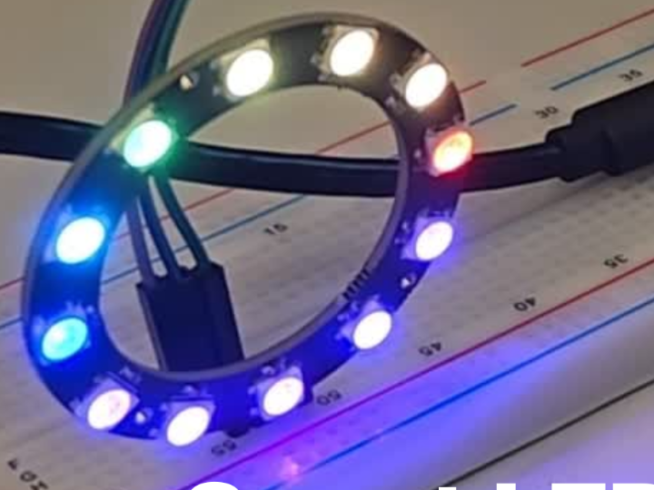
Smart LED control with Adafruit. io and MQTT
Control LED lights in real-time using a switch, MQTT, and Adafruit IO with this Smart LED Control system!
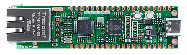
WIZnet - W5100S-EVB-Pico2
x 1
Step 1: Gather Components
For this project, you will need:
- W5100S-EVB-PICO2 Microcontroller
- Neopixel LED Ring
- Analog Switch

Step 2: Hardware Setup
The W5100S-EVB-PICO2 is an excellent choice for IoT projects. It features dual Cortex-M33 cores for efficient processing, 520kB of SRAM, and built-in Ethernet support. This makes it perfect for applications like smart home devices.

Connections
- LED Output: Connect the Neopixel LED to GPIO0.
- Switch Input: Connect the analog switch to GPIO26.
- Ethernet Connection: Connect to the Ethernet port for Adafruit IO access

Schematic
Refer to the schematic diagram to ensure correct wiring. Double-check all connections for security and accuracy before powering on the board.
Step 3: Software Configuration

Setting Up Adafruit IO
- Create an Account: Sign up for an account on Adafruit IO.
- Create Feeds: Navigate to the Feeds page and create feeds for:LED control (
light_button_feed)Brightness monitoring (brightness_feed)Rainbow mode (rainbow_feed)Color selection (color_feed) - Design Dashboard: Go to the Dashboard section to design your control interface, adding components like switches and color pickers.
Imports and Setup
- time: Used for sleep functions to control loop timing.
- neopixel: Library to control NeoPixel LEDs.
- adafruit_connection_manager: Manages network connections.
- board: Provides access to board-specific pin definitions.
- busio: Handles serial communication (SPI in this case).
- WIZNET5K: Library for the WIZNET5K Ethernet module, allowing network connectivity.
- AnalogIn: Reads analog input values, such as from a sensor.
- DigitalInOut: Configures GPIO pins for digital input/output.
- adafruit_minimqtt: Library for MQTT communication.
import time
import neopixel
import adafruit_connection_manager
import board
import busio

from adafruit_wiznet5k.adafruit_wiznet5k import WIZNET5K
from analogio import AnalogIn
from digitalio import DigitalInOut

import adafruit_minimqtt.adafruit_minimqtt as MQTT
Secrets Management
This block attempts to import a secrets dictionary containing sensitive information (like MQTT credentials). If the import fails, it notifies the user to create a secrets.py file. It's crucial to ensure that no one else has access to this file or its contents, including passwords and API keys. Always keep your credentials private and secure.
try:
    from secrets import secrets
except ImportError:
    print("MQTT secrets are kept in secrets.py, please add them there!")
    raise
Hardware Configuration
- Ethernet Connection: The WIZNET5K Ethernet module is configured to connect to the internet via SPI.
- NeoPixel Setup: A NeoPixel strip with 12 pixels is initialized on a specified GPIO pin.
- Brightness Sensor: An analog input reads the brightness level.
cs = DigitalInOut(board.GP17)
spi_bus = busio.SPI(board.GP18, MOSI=board.GP19, MISO=board.GP16)


eth = WIZNET5K(spi_bus, cs)

num_pixels = 12
pixels = neopixel.NeoPixel(board.GP0, num_pixels)

brightness = AnalogIn(board.GP26)
MQTT Connection
- Feeds: The script defines MQTT feed topics for controlling the lights, brightness, rainbow mode, and LED color.
light_button_feed = secrets["aio_username"] + "/feeds/light"
brightness_feed = secrets["aio_username"] + "/feeds/brightness"
rainbow_feed = secrets["aio_username"] + "/feeds/rainbow-mode"
color_feed = secrets["aio_username"] + "/feeds/led-color"
Callbacks: Functions are defined for handling MQTT events:
connected: Subscribes to relevant feeds when connected.
def connected(client, userdata, flags, rc):
    client.subscribe(light_button_feed)
    client.subscribe(rainbow_feed)
    client.subscribe(color_feed)
disconnected: Prints a message when disconnected.
def disconnected(client, userdata, rc):
    print("Disconnected from Adafruit IO!")
message: Processes incoming messages to control the LED behavior.
def message(client, topic, message):
    global Turn_on ,Led_looping_num ,Color_looping_num, rainbowMode, color, rainbowMode

    if topic == light_button_feed:
        if message == "1":
            print("Turn on the LEDs")
            Led_looping_num = 0
            Color_looping_num = 0
            Turn_on = True
        else:
            Turn_on = False
            print("Turn off the LEDs")

    elif topic == rainbow_feed:
        if message == "1":
            rainbowMode = True
        else:
            rainbowMode = False

    elif topic == color_feed:
        color = message
publish: Logs confirmation when a message is published to a feed.
def publish(client, userdata, topic, pid):
    print("Published to {0} with PID {1}".format(topic, pid))
    if userdata is not None:
        print("Published User dat: ", end="")
        print(userdata)
Color Handling
- Rainbow Colors: A predefined list of RGB values representing different colors in a rainbow sequence.
rainbowColorList = [
(255, 0, 0),   # Red
(255, 127, 0), # Orange
(255, 255, 0), # Yellow
(0, 255, 0),   # Green
(0, 255, 255), # Cyan
(0, 0, 255),   # Blue
(75, 0, 130),  # Indigo
(148, 0, 211), # Violet
(128, 0, 128)  # Purple
]- Hex to RGB Conversion: Since the Adafruit IO color picker uses hex color codes to represent colors, we need a utility function to convert these hex values into RGB tuples. This conversion ensures that the correct color is displayed on the NeoPixel LEDs.
def hex_to_rgb(hex_color):
    hex_color = hex_color.lstrip('#')

    r = int(hex_color[0:2], 16)
    g = int(hex_color[2:4], 16)
    b = int(hex_color[4:6], 16)

    return (r, g, b)
MQTT Client Initialization
- The MQTT client is set up with broker details and the socket pool/SSL context for network communication.
pool = adafruit_connection_manager.get_radio_socketpool(eth)
ssl_context = adafruit_connection_manager.get_radio_ssl_context(eth)


mqtt_client = MQTT.MQTT(
    broker="io.adafruit.com",
    username=secrets["aio_username"],
    password=secrets["aio_key"],
    is_ssl=True,
    socket_pool=pool,
    ssl_context=ssl_context,
)

mqtt_client.on_connect = connected
mqtt_client.on_disconnect = disconnected
mqtt_client.on_message = message
mqtt_client.on_publish = publish

print("Connecting to Adafruit IO...")
mqtt_client.connect()
Setup all the Initialization
mqtt_client.publish(light_button_feed, "0")
mqtt_client.publish(rainbow_feed, "1")
mqtt_client.publish(color_feed, "#FFFFFF")
Turn_on = False
rainbowMode = True
Led_looping_num = 0
Color_looping_num = 0
color = "#FFFFFF"
last_published_brightness = -1
threshold = 0.1
Main Loop
Infinite Loop: In the main loop:
- The MQTT client processes incoming messages.
If the LEDs are turned on:
- The current brightness is read from the analog input and published if it changes significantly.
- If rainbow mode is active, the NeoPixels display a looping rainbow effect, and the brightness is published.
- If not in rainbow mode, the NeoPixels are filled with a specified color.
- If the LEDs are turned on:The current brightness is read from the analog input and published if it changes significantly.
- If rainbow mode is active, the NeoPixels display a looping rainbow effect, and the brightness is published.If not in rainbow mode, the NeoPixels are filled with a specified color.
- If the LEDs are turned off, the strip is set to black (off).
while True:

    mqtt_client.loop()
    if Turn_on :
        current_brightness = brightness.value / 65536
        pixels.brightness = current_brightness


        if last_published_brightness == -1 or abs(current_brightness - last_published_brightness) >= threshold:
            mqtt_client.publish(brightness_feed, int(current_brightness * 100))
            last_published_brightness = current_brightness


        if rainbowMode:
            pixels.brightness = brightness.value/65536
            mqtt_client.publish(brightness_feed, int(brightness.value/65536 * 100))

            pixels[Led_looping_num % num_pixels] = rainbowColorList[len(rainbowColorList)-1-(Color_looping_num % len(rainbowColorList))]
            Led_looping_num+=1
            Color_looping_num+=1
        else:

            pixels.fill(hex_to_rgb(color))
    else:
        pixels.fill((0,0,0))

    time.sleep(0.5)
Step 4: Video Demonstration
The video will walk you through step-by-step guidance for setting up the hardware and software, as well as the live demonstration of the LED control. You’ll see how to access the Adafruit IO dashboard, adjust the LED color and brightness, and observe the real-time updates thanks to MQTT.
Here’s a video showing the project in action:
Conclusion
To recap, today we explored how to create a Smart LED Control system using the W5100S-EVB-PICO2, Adafruit IO, and MQTT. I encourage you to try this project yourself and share your results! For more resources and information, check the links in the description below. Thanks for watching, and happy coding!
-
Code

-
Circuit diagram
