
Say goodbye to Ethernet design hassles
Say goodbye to Ethernet design hassles: the W5500io-M module enables stable network connectivity in just 3 steps!
1 Introduction
In fields such as industrial control, the Internet of Things (IoT), and smart homes, the demand for embedded devices to connect to Ethernet is growing. However, traditional Ethernet solutions are complex to design, requiring independent selection of Ethernet chips, PHY chips, network transformers, RJ45 connectors, as well as PCB layout optimization, EMC debugging, and many other challenges. This not only results in long development cycles but also makes communication unstable due to improper hardware design.
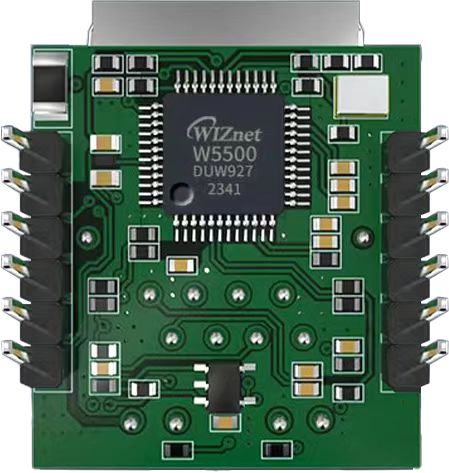
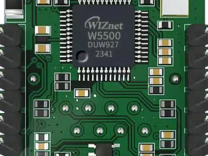
The W5500io-M is a high-performance SPI-to-Ethernet module launched by Weishi, with the following features:
- Minimalist Design: Integrates MAC, PHY, 32KB cache, and RJ45 Ethernet port. Directly connects to the main controller via a 4-wire SPI interface. Powered by 3.3V. Compact size suitable for embedded scenarios.
- Easy to Use: Users no longer need to port complex TCP/IP protocol stacks to the MCU; development can be done directly based on application-layer data.
- Abundant Resources: Provides rich MCU application examples and hardware reference designs for direct reference, greatly shortening development time. Hardware compatible with W5100Sio-M modules, facilitating solution development and iteration.
- Wide Applications: Widely used in industrial control, smart grids, charging piles, security and fire protection, new energy, and energy storage.
2 Project Environment
2.1 Hardware Preparation
- W5500io-M module
- STM32F103VCT6 development board
- One network cable
- Several DuPont wires
- Switch or router
2.2 Software Preparation
- Example link: w5500.com/w5500.html
- Development environment: Keil uVision 5
- Freescale Serial Port Assistant
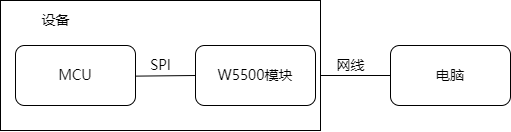
2.3 Scheme Diagram
3 Simple Steps to Connecting to the Internet
Using the W5500IO-M, you can reliably connect your device to the Ethernet network in just three simple steps:
3.1 Connecting the SPI Interface
The module provides standard SPI interfaces (SCLK, MOSI, MISO, SCS) for direct connection to your MCU (such as STM32, Arduino, ESP32, etc.).
It operates on a single 3.3V power supply, is compatible with mainstream development boards, and requires no additional power supply circuit design.
//W5500_SCS    --->    STM32_GPIOD7    /*W5500的片选引脚*/
//W5500_SCLK    --->    STM32_GPIOB13    /*W5500的时钟引脚*/
//W5500_MISO    --->    STM32_GPIOB14    /*W5500的MISO引脚*/
//W5500_MOSI    --->    STM32_GPIOB15    /*W5500的MOSI引脚*/
//W5500_RESET    --->    STM32_GPIOD8    /*W5500的RESET引脚*/
//W5500_INT    --->    STM32_GPIOD9    /*W5500的INT引脚*/
3.2 Connecting the Network Cable
The module integrates a network port with a network transformer, eliminating the need for an external magnetic coupling isolation circuit.
Supports 10/100Mbps auto-sensing, plug and play.
3.3 Porting Mature Drivers for Fast Communication
The W5500 chip has a built-in hardware protocol stack, supporting TCP/IP/UDP/ICMP/DHCP, significantly reducing the MCU's workload.
Rich examples are provided to accelerate the development process. Examples and documentation can be found at w5500.com/w5500.html.
4 Porting Process
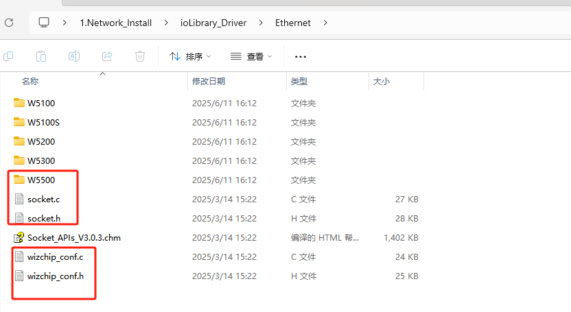
4.1 Add the following files from the example files to your own project
Taking the STM32F103VCT6 microcontroller as an example, refer to the "Network_Install" project in the example documentation and follow these steps:
(1) Copy the W5500 folder, socket.c, socket.h, wizchip_conf.c, and wizchip_conf.h files located in the ioLibrary_Driver\Ethernet folder to your own project.
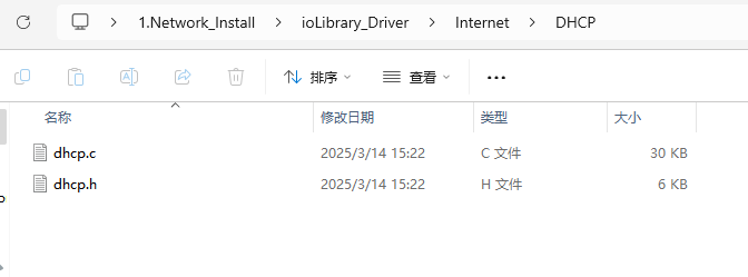
(2) Copy the dhcp.c and dhcp.h files located in the ioLibrary_Driver\Internet\DHCP folder to your own project.
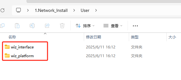
(3) Copy the wiz_interface and wiz_platform folders located in the User folder to your own project.
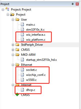
(4) Port the project directory.
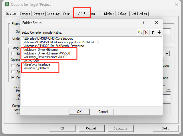
4.2 Add the corresponding header file directory to the project
4.3 Adapt the relevant interfaces in the wiz_platform.c file
(1) Adapt serial port functions
void debug_usart_init(void)
{
   GPIO_InitTypeDef GPIO_InitStructure;
   USART_InitTypeDef USART_InitStructure;
   /* config USART1 clock */
   RCC_APB2PeriphClockCmd(RCC_APB2Periph_USART1 | RCC_APB2Periph_GPIOA, ENABLE);

   /* USART1 GPIO config */
   /* Configure USART1 Tx (PA.09) as alternate function push-pull */
   GPIO_InitStructure.GPIO_Pin = GPIO_Pin_9;
   GPIO_InitStructure.GPIO_Mode = GPIO_Mode_AF_PP;
   GPIO_InitStructure.GPIO_Speed = GPIO_Speed_50MHz;
   GPIO_Init(GPIOA, &GPIO_InitStructure);
   /* Configure USART1 Rx (PA.10) as input floating */
   GPIO_InitStructure.GPIO_Pin = GPIO_Pin_10;
   GPIO_InitStructure.GPIO_Mode = GPIO_Mode_IN_FLOATING;
   GPIO_Init(GPIOA, &GPIO_InitStructure);

   /* USART1 mode config */
   USART_InitStructure.USART_BaudRate = 115200;
   USART_InitStructure.USART_WordLength = USART_WordLength_8b;
   USART_InitStructure.USART_StopBits = USART_StopBits_1;
   USART_InitStructure.USART_Parity = USART_Parity_No;
   USART_InitStructure.USART_HardwareFlowControl = USART_HardwareFlowControl_None;
   USART_InitStructure.USART_Mode = USART_Mode_Rx | USART_Mode_Tx;
   USART_Init(USART1, &USART_InitStructure);

   USART_Cmd(USART1, ENABLE);
}
(2) Adapting timer functions
void wiz_timer_init(void)
{
   TIM_TimeBaseInitTypeDef TIM_TimeBaseStructure;
   NVIC_InitTypeDef NVIC_InitStructure;

   RCC_APB1PeriphClockCmd(RCC_APB1Periph_TIM2, ENABLE);
   TIM_TimeBaseStructure.TIM_Period = 1000 - 1;
   TIM_TimeBaseStructure.TIM_Prescaler = 72 - 1;
   TIM_TimeBaseStructure.TIM_ClockDivision = TIM_CKD_DIV1;
   TIM_TimeBaseStructure.TIM_CounterMode = TIM_CounterMode_Up;

   TIM_TimeBaseInit(TIM2, &TIM_TimeBaseStructure);
   TIM_ClearFlag(TIM2, TIM_FLAG_Update);
   TIM_ITConfig(TIM2, TIM_IT_Update, ENABLE);

   NVIC_PriorityGroupConfig(NVIC_PriorityGroup_0);
   NVIC_InitStructure.NVIC_IRQChannel = TIM2_IRQn;
   NVIC_InitStructure.NVIC_IRQChannelPreemptionPriority = 0;
   NVIC_InitStructure.NVIC_IRQChannelSubPriority = 3;
   NVIC_InitStructure.NVIC_IRQChannelCmd = ENABLE;
   NVIC_Init(&NVIC_InitStructure);
   TIM_Cmd(TIM2, ENABLE);
}
(3) Adapting SPI functions
void wiz_spi_init(void)
{
   RCC_APB1PeriphClockCmd(RCC_APB1Periph_SPI2, ENABLE);
   RCC_APB2PeriphClockCmd(RCC_APB2Periph_GPIOB|RCC_APB2Periph_GPIOD, ENABLE);
   GPIO_InitTypeDef GPIO_InitStructure;
   GPIO_InitStructure.GPIO_Pin = GPIO_Pin_13 | GPIO_Pin_14 | GPIO_Pin_15;
   GPIO_InitStructure.GPIO_Mode = GPIO_Mode_AF_PP;
   GPIO_InitStructure.GPIO_Speed = GPIO_Speed_50MHz;
   GPIO_Init(GPIOB, &GPIO_InitStructure);

   SPI_InitTypeDef SPI_InitStructure;
   SPI_InitStructure.SPI_Direction = SPI_Direction_2Lines_FullDuplex;
   SPI_InitStructure.SPI_Mode = SPI_Mode_Master;
   SPI_InitStructure.SPI_DataSize = SPI_DataSize_8b;
   SPI_InitStructure.SPI_CPOL = SPI_CPOL_Low;
   SPI_InitStructure.SPI_CPHA = SPI_CPHA_1Edge;
   SPI_InitStructure.SPI_NSS = SPI_NSS_Soft;
   SPI_InitStructure.SPI_BaudRatePrescaler = SPI_BaudRatePrescaler_8;
   SPI_InitStructure.SPI_FirstBit = SPI_FirstBit_MSB;
   SPI_Init(SPI2, &SPI_InitStructure);
   SPI_Cmd(SPI2, ENABLE);

   /* PD_7 -> CS */
   GPIO_InitStructure.GPIO_Mode = GPIO_Mode_Out_PP;
   GPIO_InitStructure.GPIO_Pin = WIZ_SCS_PIN;
   GPIO_Init(WIZ_SCS_PORT, &GPIO_InitStructure);
   GPIO_SetBits(WIZ_SCS_PORT, WIZ_SCS_PIN);
}
void wizchip_select(void)
{
   GPIO_ResetBits(WIZ_SCS_PORT, WIZ_SCS_PIN);
}
void wizchip_deselect(void)
{
   GPIO_SetBits(WIZ_SCS_PORT, WIZ_SCS_PIN);
}
void wizchip_write_byte(uint8_t dat)
{
   while (SPI_I2S_GetFlagStatus(SPI2, SPI_I2S_FLAG_TXE) == RESET)
   {
   }
   SPI_I2S_SendData(SPI2, dat);
   while (SPI_I2S_GetFlagStatus(SPI2, SPI_I2S_FLAG_RXNE) == RESET)
   {
   }
   SPI_I2S_ReceiveData(SPI2);
}
uint8_t wizchip_read_byte(void)
{
   while (SPI_I2S_GetFlagStatus(SPI2, SPI_I2S_FLAG_TXE) == RESET)
   {
   }
   SPI_I2S_SendData(SPI2, 0xffff);
   while (SPI_I2S_GetFlagStatus(SPI2, SPI_I2S_FLAG_RXNE) == RESET)
   {
   }
   return SPI_I2S_ReceiveData(SPI2);
}
(4) Adapting the reset function
void wizchip_reset(void)
{
   GPIO_SetBits(WIZ_RST_PORT,WIZ_RST_PIN);
   delay_ms(10);
   GPIO_ResetBits(WIZ_RST_PORT,WIZ_RST_PIN);
   delay_ms(10);
   GPIO_SetBits(WIZ_RST_PORT,WIZ_RST_PIN);
   delay_ms(10);
}
4.4 移植主函数内容
#include "stm32f10x.h"
#include <stdio.h>
#include "wiz_platform.h"
#include "wizchip_conf.h"
#include "wiz_interface.h"
#define ETHERNET_BUF_MAX_SIZE (1024 * 2)

/* network information */
wiz_NetInfo default_net_info = {
   .mac = {0x00, 0x08, 0xdc, 0x12, 0x22, 0x12},
   .ip = {192, 168, 1, 30},
   .gw = {192, 168, 1, 1},
   .sn = {255, 255, 255, 0},
   .dns = {8, 8, 8, 8},
   .dhcp = NETINFO_STATIC}; // static ip
uint8_t ethernet_buf[ETHERNET_BUF_MAX_SIZE] = {0};

int main(void)
{
    wiz_NetInfo net_info;
    delay_init();
   debug_usart_init();
   wiz_timer_init();
   wiz_spi_init();
   wiz_rst_int_init();
   printf("%s network install example\r\n",_WIZCHIP_ID_);

    /* wizchip init */
    wizchip_initialize();

    network_init(ethernet_buf, &default_net_info);

    wizchip_getnetinfo(&net_info);
    printf("please try ping %d.%d.%d.%d\r\n", net_info.ip[0], net_info.ip[1], net_info.ip[2], net_info.ip[3]);
5. Functional Verification After running the example program, you will first see a PHY link test performed, followed by the printing of the configured network address information and PING prompts.
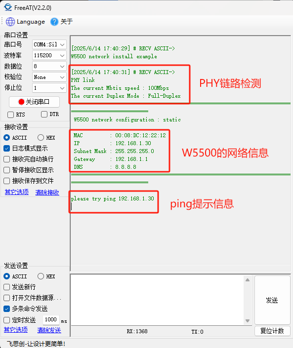
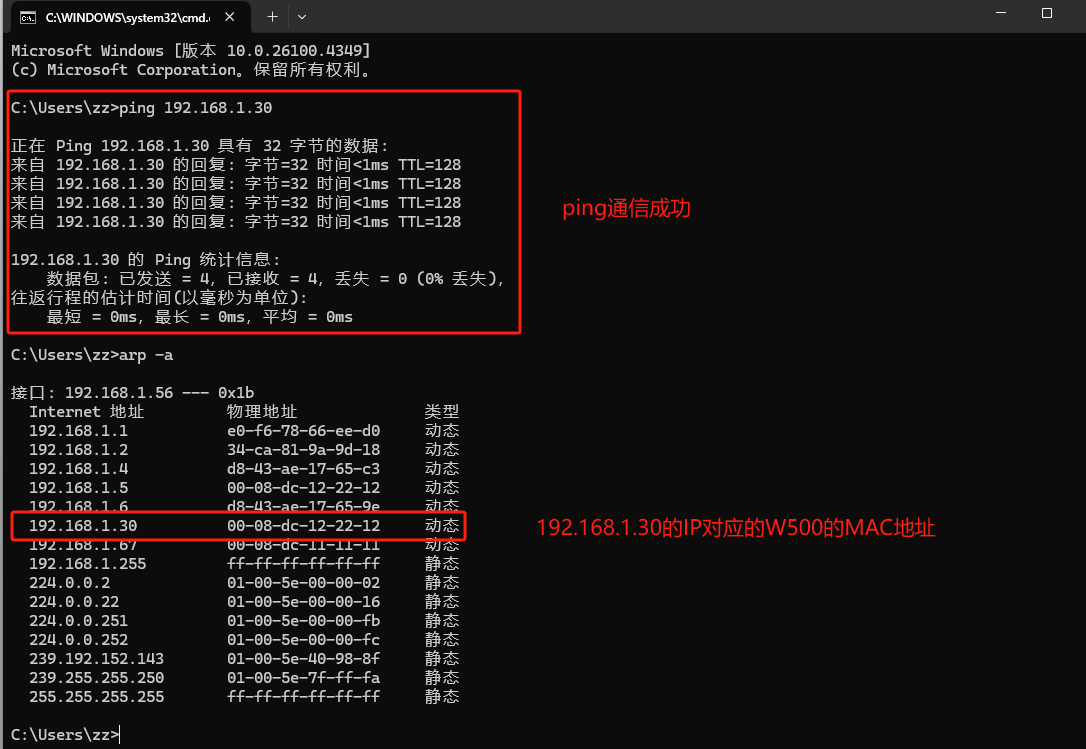
Ping the W5500's IP address (192.168.1.30) from the PC will succeed.
6. Summary This article introduces the functional characteristics of the W5500IO-M module and its advantages in embedded Ethernet access. This module is simple in design, easy to use, and can significantly shorten the development cycle. Thank you for reading! If you have any questions about this article or would like to learn more about this product, please feel free to leave a message via private message or in the comments section. We will reply to your message as soon as possible!
———————————————— Copyright Notice: This article is an original article by CSDN blogger "Playing with Ethernet" and is licensed under CC 4.0 BY-SA. Please include the original source link and this statement when reprinting.
Original link: https://blog.csdn.net/2301_81684513/article/details/148656547