
Mini Smart Home System with Android App part 2
Mini Smart Home System with Android App part 2
WIZnet - W5100S-EVB-Pico2
x 1
Story
Introduction
Hello, this is an update to my previous Project on Android App with W5100S-EVB-Pico 2. In this project, I have improved the design on the system to support more hardware using relays. With such, you can also create a similar mini smart home system like this in your personal projects.
This article will first cover the components needed for the new system, the connection of the modules with our board, and finally the codes in both Android Studio and CircuitPython
Components
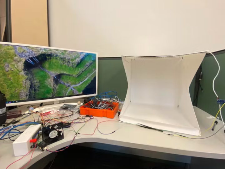
To improve the project, I added a 12V NMB-MAT fan by Minebea Motor and custom made light box for simulating a home system. To operate these devices, you would need 2 external power supplies to use both of these products as our board only supports 5V and 3.3V.
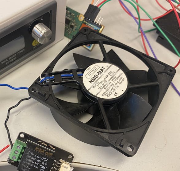
Also, to allow our board to power up the hardware, you will need a relay or a N-channel MOSFET module. Both are used so that by providing the signals from our board to modules, they will then allow the external power supply to power up the hardware by their respective mechanics.
The power supply used for the fan is a XY-SK35 power supply as it allows voltage level up to 24Vs and for the custom light box, you would only need a microUSB to USB wire alongside a USB plug as the power supply for the light box.
_HwOzhunfgx.jpeg?auto=compress%2Cformat&w=740&h=555&fit=max)
The upon components along with our Pico 2 board will be connected with a relay module.
For the box with light strips, you will need a MOSFET module in order to run PWM onto this strip of light.
Hardware Connection
For each of the hardware, we will first connect the control module (Relay/MOSFET), power supply and the hardware, and then we will connect the completed circuit back to the board.
During my research, I came across this video that teaches me how to connect the relay with the hardware and how to control it with the Pico board.
To connect the fan, the relay and the power supply, you would need to do the following.
1. Identify which circuit you want to use.
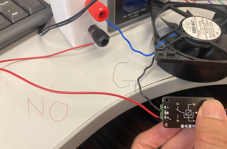
- If you want the hardware to work when the board provides a LOW signal, you would need to use NC port of the relay, meaning the power supply-to-fan circuit is kept closed when the respective pin on the board outputs a LOW signal, indicating the fan only operates when signal is LOW.
- If you want the hardware to work only when the board provides a HIGH signal, you would need the NO port of the relay, meaning the power supply-to-fan circuit is kept open when the pin is LOW, indicating the fan will not operate when signal is LOW.
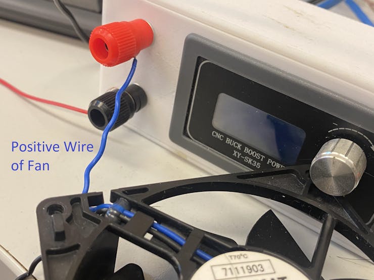
2. Connect the positive port of the fan to the positive terminal of the power supply. You may need to use a wire stripper to allow the copper wire to connect to the power supply's positive terminal. I cut the wire's plastic coating and wrap around the positive terminal of the power supply. (The blue wire is positive wire of fan)
3. Connect the ground wire of the fan to the COM port of the relay with the ground port of the fan.
4. Lastly, connect the negative terminal of the power supply to the chosen port from step 1 (NO/NC). For this project, I want the fan to operate only when my board sends a HIGH signal, meaning I will be using the NO port
This completes the Power supply-Fan Circuit.
To connect to the board, simply attach the ground, voltage, and signal pin to respective pins and the signal should be in DigitalInOut pin in CircuirPython
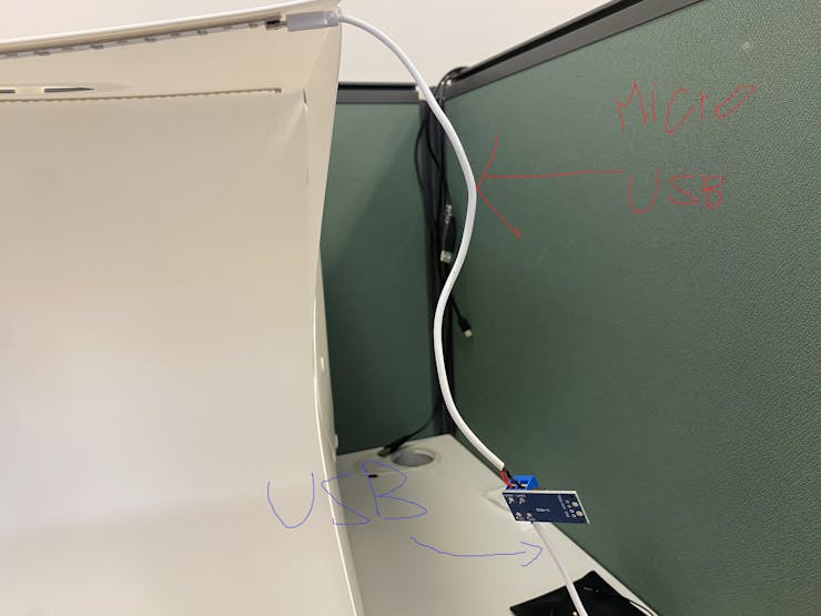
Next, for the light box, you will need the following procedure.
1. Cut and remove the plastic coatings of the microUSB-to-USB wire. Expose some of the copper wire for electricity to pass through. You should now have two sections of the wire, which I will referencing them as the microUSB wire and the USB wire.
2. In the N-MOS module, you will find 4 ports, which are the V Input +/- and V Output+/-. Attach the microUSB wire's positive and negative pole to the Voltage Output Positive port and Negative port respectively. For the Voltage In, we connect the USB wire accordingly.
3. You should find there 6 ports on the other side of the module. The three ports at the top are all for PWM and the rest are ground.
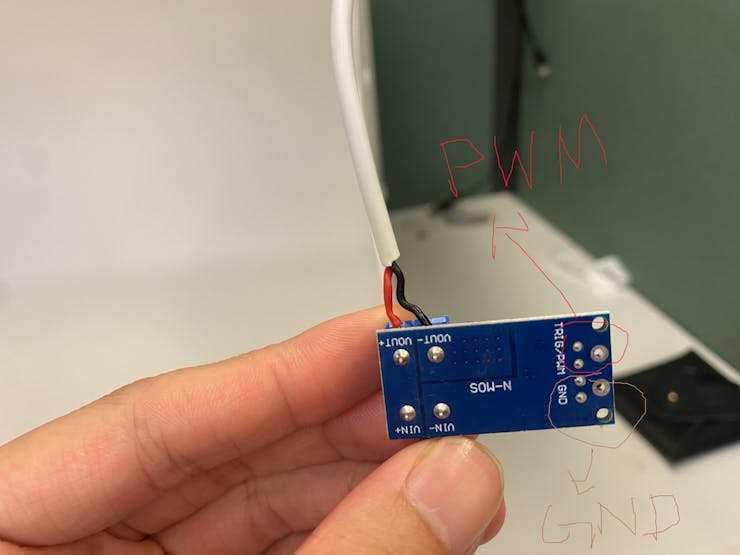
We would then need to connect these ports to the board's pin. I used GP12 as the pin for this module.
This completes the connection of both of the hardware.
CircuitPython Code
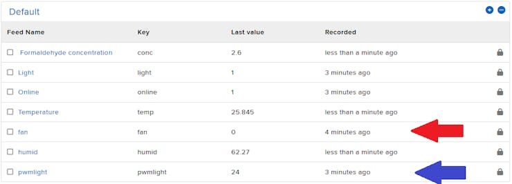
Before writing the code, create two more feeds for fan and PWM light on Adafruit IO so that you can read or write these values as Adafruit mode
To allow our app to turn the fan/box light on/off, you will need to set up a new endpoint for both of these two hardwar.
To use the fan, I bind the Gp9 pin as the DigitalInOut pin and when this pin value is 1, the fan will turn on, if not then the fan will be off.
I have also added an Automated version where if the temperature from the SFA30 exceeds certain value, the fan will automatically turn on.
# Relay Fan
fan = DigitalInOut(board.GP9)
fan.direction = Direction.OUTPUT
fan.value = False
recorded_temp = 0
Since now we want the SFA30 to record the variables automatically instead of performing the calculations only when we call to the SFA 30 endpoint, we move the codes in the SFA30 endpoint responsible to retrieve data out to a function where we will call every loop when the server is online.
We will return the fan value also in the new version alongside these data for the App to use, where I will explain later.
Previous version on local mode:
@server.route("/SFA30")
def check_temp(request: Request):
    # DHT verion
    # return JSONResponse(request,{"Temp": dht.temperature, "Humidity": dht.humidity})
    global readings, recorded_temp
    recv_data = bytearray()

    # Obtain Data
    SFA_get_data = bytearray([0x7E ,0x00 ,0x03 ,0x01 ,0x02 ,0xF9 ,0x7E])
    SFA30.write(SFA_get_data)
    time.sleep(0.5)
    segmented_frame = SFA30.readline()

    while segmented_frame != None:
        recv_data.extend(segmented_frame)
        segmented_frame = SFA30.readline()

    print(recv_data)
    readings = set_reading_values(recv_data)
    recorded_temp = readings[2]

    return JSONResponse(request,{"Temp": readings[2], "Humidity": readings[1],"HCHO": readings[0]})
Current version on local mode:
// Moved calculations to a function
def auto_temp():
    global readings, recorded_temp
    recv_data = bytearray()

    # Obtain Data
    SFA_get_data = bytearray([0x7E ,0x00 ,0x03 ,0x01 ,0x02 ,0xF9 ,0x7E])
    SFA30.write(SFA_get_data)
    time.sleep(0.5)
    segmented_frame = SFA30.readline()

    while segmented_frame != None:
        recv_data.extend(segmented_frame)
        segmented_frame = SFA30.readline()

    print(recv_data)
    readings = set_reading_values(recv_data)
    recorded_temp = readings[2]


@server.route("/SFA30")
def check_temp(request: Request):
    global readings, recorded_temp
    return JSONResponse(request,{"Temp": readings[2], "Humidity": readings[1],"HCHO": readings[0], "fan":fan.value == 1})


//Inside the loop for local mode
while connection:
    auto_temp()
    if recorded_temp >= 25:
        fan.value = 1
    else:
        fan.value = 0

    try:
        server.poll()
    except (ConnectionError, RuntimeError) as e:
        server.stop()
        local_network = False
        print("Connection Closed")
        break


...
In Adafruit mode, you would need to add a new feed for the fan value, subscribe to it, and post the value to Adafruit IO after the calculations.
# Inside Feed Intialization
...
fan_feed  = f"{secrets["aio_username"]}/feeds/fan"
...

#Inside connected function
def connected(client,userdata,flags,rc):
    ...
    client.subscribe(fan_feed)
    ...
During the first iteration, we will need to post the current fan value to Adafruit IO first when it reaches the temperature threshold (Code here is 25).
# Initial Publish

SFA_get_data = bytearray([0x7E ,0x00 ,0x03 ,0x01 ,0x02 ,0xF9 ,0x7E])
SFA30.write(SFA_get_data)
time.sleep(0.2)
recv_data= bytearray()
segmented_frame = SFA30.readline()
while segmented_frame != None:
    recv_data.extend(segmented_frame)
    segmented_frame = SFA30.readline()
readings = set_reading_values(recv_data)

mqtt_client.publish(online_feed,1)
mqtt_client.publish(temp_feed, readings[2])
mqtt_client.publish(humid_feed, readings[1])
mqtt_client.publish(conc_feed, readings[0])
recorded_temp = readings[2]

if recorded_temp >= 25:
    fan.value = 1
    mqtt_client.publish(fan_feed, fan.value)
elif recored_temp < 25:
    fan.value = 0
    mqtt_client.publish(fan_feed, fan.value)
Inside the while loop, as to avoid reaching the throttle error of Adafruit IO, it is better to only publish the fan value when the state of the fan is changed. Increase the throttle time also to help reduce the possibility of reaching the throttle time.
AVOID_THROTTLE_TIME = 15  # Previous is 10

...
while not local_network:
    mqtt_client.loop()
    current = time.monotonic()

    # Send Data after certain time frame
    if current - last_request_time >= AVOID_THROTTLE_TIME:


        # Obtain Data
        SFA_get_data = bytearray([0x7E ,0x00 ,0x03 ,0x01 ,0x02 ,0xF9 ,0x7E])
        SFA30.write(SFA_get_data)
        time.sleep(0.2)
        recv_data= bytearray()
        segmented_frame = SFA30.readline()
        while segmented_frame != None:
            recv_data.extend(segmented_frame)
            segmented_frame = SFA30.readline()

        readings = set_reading_values(recv_data)
        recorded_temp = readings[2]
        mqtt_client.publish(temp_feed, readings[2])
        mqtt_client.publish(humid_feed, readings[1])
        mqtt_client.publish(conc_feed, readings[0])

        if recorded_temp >= 25 and fan.value != 1:
            fan.value = 1
            mqtt_client.publish(fan_feed, fan.value)
        elif recorded_temp < 25 and fan.value != 0:
            fan.value = 0
            mqtt_client.publish(fan_feed, fan.value)
...
Lastly, publish the state of the fan back to default (which is off) if the server ended.
except (KeyboardInterrupt, OSError, TypeError) as e:
    ...
    mqtt_client.publish(fan_feed,0)
    ...
To use the light, you will need to use the PWMIO library to adjust the brightness.
from pwmio import PWMOutBind the pin on GP12 with the PWMOut function. The previous_PWM variable is used to recorded the PWM value before we close the light in the app. We initialize it at 65535 because the initial state of the light is off, and if we toggle the light on the app, the duty cycle can only be set to the max value which is 65535.
# BoxLight
boxlight = PWMOut(board.GP12)
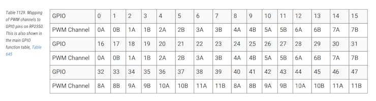
boxlight_pwm_stored = 65535 # We suppose the user turn the light to max firstOne interesting finding during my development of this section happens when I received an error with All timer used. After some research, I found out that this happens because I used the second channel of the same PWM Output slice. As in the previous code I used PWM output for playing the sound if connected, which is at Pin 26, I accidentally used another channel of the same PWM slice for the light, which is pin 11. You can read this website for a shorter explanation on the PWM channels of the Pico 2 board or you can refer to the RP2350 datasheet.
Since both hardware each works differently, the easiest solution is to change my light to another slice of the PWM output, which is pin GP12.
Next, we amend the toggle light endpoint to use our custom light box instead of the led module.
If the current state is 0, we turn it on to the previously stored PWM value as the brightness.
If the currents state is non-zero, we turn it off.
@server.route("/light")
def toggle_light(request:Request):
   if boxlight.duty_cycle == 0:
       boxlight.duty_cycle = boxlight_pwm_stored
   else:
       boxlight.duty_cycle = 0
   s = "Turned on" if boxlight.duty_cycle > 0 else "Turned off"
We should also add another route for changing the PWM value of the light.
As the Android scales from 0-100, we map these values to 0-65535 by the following way and store the calculated result back to the previous_PWM variable.
@server.route("/lightbox", POST)
def lightbox_change(request:Request):
    global boxlight_pwm_stored
    uploaded_body = request.json()
    boxlight.duty_cycle = int(65535 * (uploaded_body["value"]/100))
    boxlight_pwm_stored = boxlight.duty_cycle
    return Response(request,"Complete toggle")
Next, for Adafruit mode, create the boxlight feed and subscribe to it in the connected MQTT function.
...
boxlight_feed  = f"{secrets["aio_username"]}/feeds/pwmlight"
...

def connected(client, userdata, flags, rc):
    ...
    client.subscribe(boxlight_feed)
    ...
We also need to amend the message function. The app will still call to the LED endpoint for turning lights on/off, but the app may now post the slider value to the PWM endpoint to adjust the brightness.
If the app is posted to the light feed, our boxlight will change the brightness to previously-stored state if it is on, 0 if it is off.
If the app post to the boxlight feed, we first set the duty cycle accordingly with the app's value with this formula and store the current duty cycle value into the previous_PWM variable so that if we reopen the light, the brightness is at the previously stored state.
def message(client, topic, message):
    global boxlight_pwm_stored
    print("Boxlight:",boxlight_pwm_stored)
    if topic == light_feed:
        boxlight.duty_cycle = boxlight_pwm_stored if int(message) else 0
    elif topic == boxlight_feed:
        boxlight.duty_cycle = int(65535 * (int(message)/100))
        boxlight_pwm_stored = boxlight.duty_cycle
We would also need to post the current brightness of the light if we change from local mode to Adafruit.
mqtt_client.publish(online_feed,1)

if boxlight.duty_cycle > 0:
    mqtt_client.publish(light_feed, 1)
else:
    mqtt_client.publish(light_feed, 0)

mqtt_client.publish(temp_feed, readings[2])
mqtt_client.publish(humid_feed, readings[1])
mqtt_client.publish(conc_feed, readings[0])
Lastly, publish the default value of the duty cycle to Adafruit IO, which is 0
except (KeyboardInterrupt, OSError, TypeError) as e:
            power = False
            mqtt_client.publish(online_feed,0)
            mqtt_client.publish(light_feed,0)
            mqtt_client.publish(boxlight_feed,0)
            mqtt_client.disconnect()
This completes the CircuirPython codes.
Android Studio Code
In the Android App, you will need to add a button Image to store the current state of the fan and add the button responsible for toggling the brightness of the light alongside a slider that makes up the PWM value.
I used the ImageButton Component for the fan as in the previous version, I allowed it to turn on or off the fan by pressing this button. In the future, I might include a auto/manual toggle so that this serves as both a Static image component if it is auto fan mode, but if it is manual mode, we can press this button to turn on and off.
The images for Fan on and Fan off are generated from ChatGPT. You can make your own version and rename it as fan_on, fan_off and store it into /res/drawable folder.

Here is my code in activity_main xml.
<FrameLayout
    android:id="@+id/bulbContainer"
    android:layout_width="371dp"
    android:layout_height="318dp"
    android:layout_alignParentStart="true"
    android:layout_alignParentTop="true"
    android:layout_alignParentEnd="true"
    android:layout_marginStart="21dp"
    android:layout_marginTop="252dp"
    android:layout_marginEnd="888dp"
    android:background="@color/grey"
    android:padding="16dp"
    android:stateListAnimator="@animator/pop_down_animator">

    <ImageButton
        android:id="@+id/lightButton"
        android:layout_width="match_parent"
        android:layout_height="match_parent"
        android:adjustViewBounds="true"
        android:background="@color/grey"
        android:clickable="true"
        android:focusable="true"
        android:scaleType="fitCenter"
        android:src="@drawable/bulb_off"


        />


</FrameLayout>
<SeekBar
    android:id="@+id/seekBar"
    android:layout_width="372dp"
    android:layout_height="58dp"
    android:layout_below="@+id/bulbContainer"
    android:layout_alignParentEnd="true"
    android:layout_alignParentBottom="true"
    android:layout_marginTop="8dp"
    android:layout_marginEnd="884dp"
    android:layout_marginBottom="164dp" />

<Button
    android:id="@+id/slidebutton"
    android:layout_width="331dp"
    android:layout_height="78dp"
    android:layout_alignParentTop="true"
    android:layout_alignParentEnd="true"
    android:layout_alignParentBottom="true"
    android:layout_marginTop="645dp"
    android:layout_marginEnd="903dp"
    android:layout_marginBottom="78dp"
    android:background="@drawable/button_background"
    android:text="Apply"
    android:textSize="24sp" />
Next, let's move to the logic behind these components.
Set up the slider and buttons as follows. As the SeekBar changes, we will store the changed result to a slider value variable that will be used to send to the board when we decide to press the Apply button which is responsible for the brightness.
I also assigned fan_button to be false because we currently will not support manually changing the fan.
// Slider and Button
val slider = binding.seekBar
val slider_button = binding.slidebutton
var slider_value:Int = 0

slider.max = 100
slider.setOnSeekBarChangeListener(object: OnSeekBarChangeListener{
    override fun onProgressChanged(seekBar: SeekBar?, progress: Int, fromUser: Boolean) {
        slider_value = progress
    }

    override fun onStartTrackingTouch(seekBar: SeekBar?) {
        //pass
    }

    override fun onStopTrackingTouch(seekBar: SeekBar?) {
       // pass
    }
})


// fan button
val fan_button = binding.fanButton
fan_button.isEnabled = false
Create the Adafruit IO endpoints for making the HTTP requests.
// Adafruit URL
...
val endpoint_lightbox = "https://io.adafruit.com/api/v2/$ac/feeds/pwmlight/data"
val endpoint_fan = "https://io.adafruit.com/api/v2/$ac/feeds/fan/data"
Since we have added a few new components onto the App, we need to disable these new components when the network is down.
discoveryJob = lifecycleScope.launch(Dispatchers.IO) {
            while (isActive) {
                if (!isNetworkAvailable()) {
                    withContext(Dispatchers.Main) {
                        editbox.setText("Offline")
                        arcGauge.value = 0.0
                        halfGauge.value = 0.0
                        t2.text = ""
                        buttonBulb.isEnabled = false
                        slider_button.isEnabled = false
                        fan_button.isEnabled = false
                    }
                    delay(10_000)
                    continue   // try again in 10s, don’t kill the loop
                } else {
                    withContext(Dispatchers.Main){
                        buttonBulb.isEnabled = true
                    }
                }
...
We can now code the slider button. Most of the logic behind this slider button is very similar to the other buttons, but I added a small section where I will tell the user that you need to turn on the lights before pressing the Apply button.
slider_button.setOnClickListener() {
    if (!slider_button.isEnabled) return@setOnClickListener
    if (!buttonState) {
        t2.text = "Turn on light before toggle"
        return@setOnClickListener
    }
    ...
Next, depending on whether we retrieve the IP from our discoveryIoT function in the previous article, we will perform HTTP request to the respective API endpoint. Remember that in this Adafruit section, we need to identify the online status of the IOT device before fetching data from the correct feeds (i.e. pwmlight).
In this section, I used POST instead of GET request from the previous onClickListener as we will be posting numeric data to our IOT device.
...
lifecycleScope.launch {
    slider_button.isEnabled = false
    t2.text = "Loading..."
    if (ip != null) {
        netLock.withLock {
            try {
                val slider_string = slider_value.toString()
                val slider_payload = """{
                    "value":$slider_string
                }""".trimIndent()

                val response: String = client.post("http://$ip:5000/lightbox") {
                                header("Accept", "application/json")
                                contentType(ContentType.Application.Json)
                                setBody(slider_payload)
                            }.body()
                            t2.text = response

            } catch (e: Exception) {
//                            t2.text = "Error: ${e.localizedMessage}"
                        }
                    }
                }
    else {

        // Check online status
        if (io_key != null) {
             try {
                val response_online: String = client.get(endpoint_online) {
                                header("X-AIO-Key", io_key)
                            }.bodyAsText()
                var jsonArray = JSONArray(response_online)
                if (jsonArray.length() > 0) {
                    adafruit_online = jsonArray.getJSONObject(0).optInt("value", -1)
                }
             } catch (e: Exception) {
                            //pass
                }


             if (adafruit_online == 1) {
                  // Post light data
                  try {

                      val slider_string = slider_value.toString()
                      val slider_payload = """{
                                    "value":$slider_string
                      }""".trimIndent()
                      val responseText: String = client.post(endpoint_lightbox) {
                                    header("X-AIO-Key", io_key)
                                    contentType(ContentType.Application.Json)
                                    setBody(slider_payload)
                      }.bodyAsText()
                      t2.text = JSONObject(responseText).optString("value")

                  } catch (e: Exception) {
                                t2.text = "Error: ${e.localizedMessage}"
                            }
              } else {
                            t2.text = "Server not online"
                        }

                    }
                }
                slider_button.isEnabled = true
            }

        }
After completing the slider button, we can now amend the SFA 30 function where we will retrieve the fan status at the same time with the SFA30 data.
Following the previous article on the get_data_job function, we first amend the code inside local mode.
As we decide to return a JSON object with SFA30 data with the fan data from the SFA30 endpoint, we can simply check whether the "fan" key's value is true or false, and then change the fan photos accordingly..
Here is the code for the local mode
# Inside get_data_job
if (ip != null){
    netLock.withLock {
       try {
           delay(1000)
           val response: JsonObject = client.get("http://$ip:5000/SFA30") {
                                    header("Accept", "application/json")
                                }.body()

           withContext(Dispatchers.Main) {
               arcGauge.value = response["Temp"].toString().toDouble()
               halfGauge.value = response["Humidity"].toString().toDouble()
               halfGauge2.value = response["HCHO"].toString().toDouble()
               val recieved_fan_string = response["fan"].toString()
               t2.text = recieved_fan_string
               if (recieved_fan_string == "true"){
                   fan_button.setImageResource(R.drawable.fan_on)
               } else {
                   fan_button.setImageResource(R.drawable.fan_off)
               }
            }

       } catch (e: Exception) {
//                                withContext(Dispatchers.Main) {
//                                    t2.text = "Error: ${e.localizedMessage}"
//                                }
                            }
      }
...
# Below is Adafruit Mode
For the Adafruit mode, you would need to create another async await function for the http request to the fan feed and change the picture accordingly. However, if the server is not online, you will need to set the photo to fan off as default.
...
else {

    if (io_key != null) {

    // Check for online status
        try{
            val response_online: String = client.get(endpoint_online) {
                                header("X-AIO-Key", io_key)
            }.bodyAsText()
            var jsonArray = JSONArray(response_online)
            if (jsonArray.length() > 0) {
                adafruit_online = jsonArray.getJSONObject(0).optInt("value", -1)
            }
         } catch(e:Exception){
                            adafruit_online = 0
         }


           // If the Adafruit IO status is online
           if (adafruit_online == 1) {
           // Use Async to obtain the three feeds together

                val temp_fetch = async(Dispatchers.IO){
                    runCatching {
                        client.get(endpoint_temp){
                            header("X-AIO-KEY", io_key)
                        }
                       .bodyAsText().let { JSONArray(it).getJSONObject(0).optDouble("value", 0.0)}
                     }.getOrDefault(0.0)
                }

               val humid_fetch = async(Dispatchers.IO){
                     runCatching {
                         client.get(endpoint_humid){
                             header("X-AIO-KEY", io_key)
                         }
                         .bodyAsText().let { JSONArray(it).getJSONObject(0).optDouble("value", 0.0)}
                     }.getOrDefault(0.0)
                }

               val HCHO_fetch = async(Dispatchers.IO){
                   runCatching {
                       client.get(endpoint_conc){
                            header("X-AIO-KEY", io_key)
                        }
                        .bodyAsText().let { JSONArray(it).getJSONObject(0).optDouble("value", 0.0)}
                   }.getOrDefault(0.0)
               }
                val Fan_fetch = async(Dispatchers.IO){
                    runCatching {
                        client.get(endpoint_fan){
                            header("X-AIO-KEY", io_key)
                        }
                        .bodyAsText().let { JSONArray(it).getJSONObject(0).optDouble("value", 0.0)}
                      }.getOrDefault(-1)
                }

                val temp  = temp_fetch.await()
                val humid = humid_fetch.await()
                val hcho  = HCHO_fetch.await()
                val fan   = Fan_fetch.await()

                withContext(Dispatchers.Main){
                    arcGauge.value = temp
                    halfGauge.value = humid
                    halfGauge2.value = hcho
                    if (fan == 1.0){
                        fan_button.setImageResource(R.drawable.fan_on)
                    } else {
                        fan_button.setImageResource(R.drawable.fan_off)
                    }
                 }
            } else {
              // Offline
              withContext(Dispatchers.Main) {
                  arcGauge.value = 0.0
                  halfGauge.value = 0.0
                  halfGauge2.value = 0.0
                  fan_button.setImageResource(R.drawable.fan_off)
               }
        } else {
              withContext(Dispatchers.Main){t2.text = "No Key"}
          }
        delay(2000L)
        }
    }
}
This completes Kotlin codes for the Android App.
Conclusion
This concludes the update to the mini smart-home system using Kotlin and CircuitPython. I hope by this project, you learn how to operate real life hardware using relay or N-MOSFET modules as connection with our Pico board and give you some inspiration on your personal project. There may also be new updates to this system so that it serves as a more well-rounded home system project. Hope you learn something new from this article!
-
Codes
