
How to Configure a W5500 Network Stack on STM32 with ioLibrary_Driver?
This project is a practical STM32 + W5500 bring-up record focused on SPI configuration, callback registration, PHY setup, and network parameter initialization.
How to Configure a W5500 Network Stack on STM32 with ioLibrary_Driver?
Summary
This project is a practical STM32 + W5500 bring-up record focused on SPI configuration, callback registration, PHY setup, and network parameter initialization. The platform is STM32, the goal is wired Ethernet connectivity, and the W5500 acts as the SPI-connected Ethernet controller and hardware TCP/IP endpoint underneath the application. The article is useful for both education and commercial embedded work because it shows a complete initialization path rather than only describing the chip at a high level.
What the Project Does
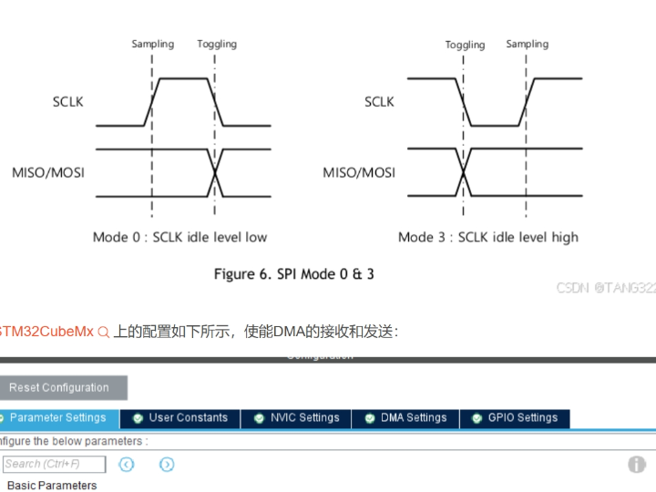
The article documents how to bring up a W5500 module on STM32, starting from SPI setup in STM32CubeMX and moving into WIZnet ioLibrary-based chip initialization. It covers SPI mode selection, DMA enablement for transmit and receive, W5500 reset handling, PHY configuration, network information loading, and driver callback registration. That makes it more than a chip overview: it is an implementation-oriented workflow for getting a real module online.
From a network-stack perspective, the design is cleanly layered. STM32 owns peripheral initialization, SPI transport, GPIO-based chip-select and reset control, and application-side policy. The W5500 owns the Ethernet-side transport model and socket resources. ioLibrary_Driver sits between them and exposes a standard interface for network identity, PHY control, and socket buffer management. That division is especially useful in commercial embedded products, because it keeps the MCU firmware focused on product logic instead of building a full software Ethernet stack from scratch.
The article also shows a practical validation step: using w5500_network_info_show() to confirm communication is working and warning that the first byte of the MAC address must be even, otherwise ping may fail. That kind of operational detail makes the write-up useful beyond education; it reflects actual bring-up issues a product team might hit during integration.
Where WIZnet Fits
The exact WIZnet product here is the W5500. The article describes it as an Ethernet-to-SPI communication chip with eight internal sockets and a fast path to network access once configured. In this system, the W5500 is not just a PHY-side helper. It is the actual network engine attached to STM32 through SPI and controlled through WIZnet’s callback-driven ioLibrary model.
Architecturally, the W5500 is the transport boundary. STM32 does not directly construct packet handling logic at the protocol level here. Instead, it registers critical-section handlers, chip-select callbacks, byte and burst SPI handlers, then lets the W5500 and ioLibrary manage the Ethernet-side behavior. That is a good fit for commercial systems that need repeatable initialization and easier maintenance, and it is equally valuable in education because it clearly exposes the MCU-to-chip interface.
The article also notes that W5500 has 16 KB receive buffer space and 16 KB transmit buffer space, and that calling wizchip_init(NULL, NULL) leaves the default 2 KB allocation per socket. That matters in real product architecture because socket buffer allocation influences concurrency and traffic behavior across the eight available sockets.
Implementation Notes
This project does use WIZnet products, and the article includes real inline code.
A verified initialization path appears in the W5500 bring-up function:
{
W5500_Reset();
reg_wizchip_cris_cbfunc(SPI_CrisEnter, SPI_CrisExit);
reg_wizchip_cs_cbfunc(SPI_CS_Select, SPI_CS_Deselect);
reg_wizchip_spi_cbfunc(SPI_ReadByte, SPI_WriteByte);
reg_wizchip_spiburst_cbfunc(SPI_BusRead, SPI_BusWrite);
wizchip_init(NULL, NULL);
w5500_phy_init();
w5500_network_info_init();
w5500_network_info_show();
reg_dhcp_cbfunc(NULL,NULL,NULL);
return 0;
}
Why it matters: this is the core architecture of the system. It shows the exact order of operations: hardware reset, platform callback registration, chip buffer initialization, PHY setup, network identity loading, and network verification. For both education and commercial development, that order is the real value of the article.
A second verified implementation block is the callback registration and network information setup:
reg_wizchip_cs_cbfunc(SPI_CS_Select, SPI_CS_Deselect);
reg_wizchip_spi_cbfunc(SPI_ReadByte, SPI_WriteByte);
reg_wizchip_spiburst_cbfunc(SPI_BusRead, SPI_BusWrite);
and
memcpy(info.ip, ip, 4);
memcpy(info.sn, sn, 4);
memcpy(info.gw, gw, 4);
memcpy(info.dns, dns, 4);
wizchip_setnetinfo(&info);
Why it matters: the first block defines the hardware abstraction boundary, and the second loads the network identity into the chip. Together they show how ioLibrary_Driver expects the host MCU to integrate the W5500: platform callbacks first, chip-level network configuration second.
The STM32-side SPI setup is also concrete. The article shows SPI1 configured as master, 8-bit, mode 0, software NSS, MSB first, with DMA enabled for RX and TX. GPIO mapping is PB3 for SCK, PB4 for MISO, and PB5 for MOSI. That means the article is grounded in a real STM32 HAL configuration rather than generic pseudocode.
Practical Tips / Pitfalls
- Start with SPI mode 0 on STM32 unless you have a clear reason to switch. The article explicitly configures polarity low and first-edge capture, which matches W5500 support.
- Register all four callback groups before calling
wizchip_init(). Missing byte or burst handlers will break communication even if basic SPI is working. - Keep reset timing conservative during bring-up. The article uses 50 ms low and 50 ms high delays in
W5500_Reset(), which is generous and practical for first integration. - Check network identity immediately after initialization with
w5500_network_info_show(). That is the fastest way to verify the chip is actually accepting configuration. - Pay attention to the MAC address rule noted by the author: the first byte should be even, otherwise ping may fail. Treat this as an observed implementation warning from the source.
- DMA-based SPI can improve throughput, but the shown implementation still blocks until
HAL_SPI_STATE_READY, so it is not yet a fully asynchronous design. In commercial products, that is an opportunity for refinement. This last point is an inference from the shown code.
FAQ
Why use the W5500 in this STM32 project?
Because it gives STM32 a wired Ethernet path through a dedicated SPI-attached controller with internal socket resources, reducing the need to build and maintain a full software Ethernet transport layer in the MCU firmware. The article specifically uses WIZnet’s ioLibrary integration model to make that boundary explicit.
How does it connect to the platform?
Through SPI1 on STM32, with PB3 as SCK, PB4 as MISO, and PB5 as MOSI in the shown CubeMX-generated initialization, plus separate GPIO-based chip select and reset handling. DMA is enabled for both receive and transmit.
What role does it play in this specific project?
It is the Ethernet engine under the application. STM32 supplies callbacks, reset control, and configuration data, while W5500 handles the network-side transport and socket buffering after initialization.
Can beginners follow this project?
Yes, if they already know basic STM32 HAL, SPI, and GPIO usage. The article is especially good for learners because it shows a complete initialization sequence instead of jumping straight into socket calls.
How does this compare with a pure software stack such as LwIP?
This approach is centered on a dedicated Ethernet controller and callback-driven integration, so it keeps more transport responsibility in hardware. A pure software stack gives more flexibility but also pushes more protocol integration and resource pressure into the MCU. That comparison is an inference from the architecture shown here.
Source
Original article: CSDN post, “W5500模块使用记录,” first published November 24, 2024, under CC 4.0 BY-SA. It documents STM32 SPI setup, DMA configuration, ioLibrary callback registration, PHY setup, and W5500 network information initialization.
Tags
W5500, WIZnet, STM32, SPI, DMA, ioLibrary_Driver, Embedded Ethernet, Socket Offload, Network Stack, Education, Commercial, HAL
STM32에서 ioLibrary_Driver와 함께 W5500 네트워크 스택을 어떻게 설정할 수 있을까?
Summary
이 프로젝트는 SPI 설정, 콜백 등록, PHY 설정, 네트워크 파라미터 초기화에 초점을 맞춘 실용적인 STM32 + W5500 구동 기록이다. 플랫폼은 STM32이고, 목표는 유선 이더넷 연결이며, W5500은 애플리케이션 아래에서 동작하는 SPI 연결 이더넷 컨트롤러이자 하드웨어 TCP/IP 엔드포인트 역할을 한다. 이 글은 칩을 높은 수준에서 설명하는 데 그치지 않고 완전한 초기화 경로를 보여주기 때문에, 교육용과 상용 임베디드 개발 모두에 유용하다.
What the Project Does
이 글은 STM32CubeMX에서 SPI 설정을 시작점으로 삼아, WIZnet ioLibrary 기반 칩 초기화까지 이어지는 W5500 모듈 구동 과정을 기록한다. 다루는 내용에는 SPI 모드 선택, 송수신 DMA 활성화, W5500 리셋 처리, PHY 설정, 네트워크 정보 로딩, 드라이버 콜백 등록이 포함된다. 즉, 단순한 칩 소개가 아니라 실제 모듈을 온라인 상태로 올리기 위한 구현 중심 워크플로다.
네트워크 스택 관점에서 보면 구조가 깔끔하게 분리되어 있다. STM32는 주변장치 초기화, SPI 전송, GPIO 기반 칩 셀렉트 및 리셋 제어, 애플리케이션 정책을 담당한다. W5500은 이더넷 측 전송 모델과 소켓 자원을 담당한다. ioLibrary_Driver는 그 사이에서 네트워크 정체성, PHY 제어, 소켓 버퍼 관리를 위한 표준 인터페이스를 제공한다. 이런 분리는 특히 상용 임베디드 제품에서 유용하다. MCU 펌웨어가 제품 로직에 집중할 수 있고, 전체 소프트웨어 이더넷 스택을 처음부터 구현할 필요가 줄어들기 때문이다.
이 글은 또 실제 검증 단계도 보여준다. w5500_network_info_show()를 사용해 통신이 정상인지 확인하고, MAC 주소의 첫 바이트는 짝수여야 하며 그렇지 않으면 ping이 실패할 수 있다고 경고한다. 이런 운영 수준의 세부사항은 이 글이 단지 교육용을 넘어, 실제 제품 통합 과정에서 부딪히는 문제도 반영하고 있음을 보여준다.
Where WIZnet Fits
여기서 사용된 정확한 WIZnet 제품은 W5500이다. 글은 W5500을 8개의 내부 소켓을 가진 이더넷-SPI 통신 칩으로 설명하며, 설정만 끝나면 빠르게 네트워크에 접근할 수 있다고 본다. 이 시스템에서 W5500은 단순한 PHY 보조 칩이 아니라, STM32에 SPI로 연결되고 WIZnet의 콜백 기반 ioLibrary 모델로 제어되는 실제 네트워크 엔진이다.
아키텍처 관점에서 W5500은 전송 경계 역할을 한다. STM32가 프로토콜 수준의 패킷 처리 로직을 직접 구성하는 것이 아니라, 크리티컬 섹션 핸들러, 칩 셀렉트 콜백, 바이트/버스트 SPI 핸들러를 등록한 뒤, W5500과 ioLibrary가 이더넷 측 동작을 관리하게 한다. 이런 구조는 반복 가능한 초기화와 유지보수가 중요한 상용 시스템에 잘 맞고, 동시에 MCU와 칩 사이 인터페이스가 명확히 드러나므로 교육용으로도 가치가 크다.
글은 또 W5500이 16 KB 수신 버퍼와 16 KB 송신 버퍼를 가지고 있으며, wizchip_init(NULL, NULL)을 호출하면 소켓당 기본 2 KB가 할당된다고 설명한다. 이는 실제 제품 설계에서 중요하다. 소켓 버퍼 할당 방식이 8개의 하드웨어 소켓 간 동시성 및 트래픽 특성에 직접 영향을 주기 때문이다.
Implementation Notes
이 프로젝트는 실제로 WIZnet 제품을 사용하며, 글에는 실제 인라인 코드도 포함되어 있다.
검증 가능한 초기화 경로 중 하나는 W5500 구동 함수다.
{
W5500_Reset();
reg_wizchip_cris_cbfunc(SPI_CrisEnter, SPI_CrisExit);
reg_wizchip_cs_cbfunc(SPI_CS_Select, SPI_CS_Deselect);
reg_wizchip_spi_cbfunc(SPI_ReadByte, SPI_WriteByte);
reg_wizchip_spiburst_cbfunc(SPI_BusRead, SPI_BusWrite);
wizchip_init(NULL, NULL);
w5500_phy_init();
w5500_network_info_init();
w5500_network_info_show();
reg_dhcp_cbfunc(NULL,NULL,NULL);
return 0;
}
이 코드가 중요한 이유는 시스템의 핵심 아키텍처를 그대로 보여주기 때문이다. 하드웨어 리셋, 플랫폼 콜백 등록, 칩 버퍼 초기화, PHY 설정, 네트워크 정체성 로딩, 네트워크 검증이라는 정확한 순서를 보여준다. 교육용과 상용 개발 모두에서 바로 이 초기화 순서가 이 글의 핵심 가치다.
두 번째로 확인 가능한 구현 블록은 콜백 등록과 네트워크 정보 설정이다.
reg_wizchip_cs_cbfunc(SPI_CS_Select, SPI_CS_Deselect);
reg_wizchip_spi_cbfunc(SPI_ReadByte, SPI_WriteByte);
reg_wizchip_spiburst_cbfunc(SPI_BusRead, SPI_BusWrite);
그리고
memcpy(info.ip, ip, 4);
memcpy(info.sn, sn, 4);
memcpy(info.gw, gw, 4);
memcpy(info.dns, dns, 4);
wizchip_setnetinfo(&info);
첫 번째 블록은 하드웨어 추상화 경계를 정의하고, 두 번째 블록은 칩에 네트워크 정체성을 로딩한다. 두 블록을 함께 보면 ioLibrary_Driver가 W5500을 어떻게 통합하도록 설계되었는지 명확해진다. 즉, 먼저 플랫폼 콜백을 준비하고, 그다음 칩 수준 네트워크 설정을 넣는 구조다.
STM32 측 SPI 설정도 구체적이다. 글은 SPI1을 마스터, 8비트, mode 0, 소프트웨어 NSS, MSB 우선으로 설정하고, RX와 TX 모두 DMA를 활성화했다고 보여준다. GPIO 매핑은 PB3가 SCK, PB4가 MISO, PB5가 MOSI다. 즉, 이 글은 일반적인 의사코드가 아니라 실제 STM32 HAL 설정 위에 서 있다.
Practical Tips / Pitfalls
- 특별한 이유가 없다면 STM32에서는 먼저 SPI mode 0으로 시작하는 편이 좋다. 글도 극성 Low, 첫 번째 에지 캡처로 설정하며, 이는 W5500 지원 방식과 맞는다.
wizchip_init()을 호출하기 전에 네 가지 콜백 그룹을 모두 등록해야 한다. 바이트 처리나 버스트 처리 핸들러가 빠지면 기본 SPI가 살아 있어도 통신이 깨진다.- 초기 구동 단계에서는 리셋 타이밍을 넉넉하게 잡는 편이 안전하다. 글의
W5500_Reset()는 Low 50 ms, High 50 ms를 사용하며, 첫 통합 단계에서는 실용적인 방식이다. - 초기화 직후
w5500_network_info_show()로 네트워크 정보를 바로 확인하는 것이 좋다. 칩이 설정을 실제로 받아들였는지 가장 빨리 확인할 수 있는 방법이다. - 글 작성자의 관찰에 따르면 MAC 주소 첫 바이트는 짝수여야 하고, 그렇지 않으면 ping이 실패할 수 있다. 이는 소스에서 직접 언급한 실제 구현 경고로 보는 편이 좋다.
- DMA 기반 SPI는 처리량 향상에 도움이 될 수 있지만, 이 글의 구현은 여전히
HAL_SPI_STATE_READY를 기다리는 블로킹 방식이다. 상용 제품에서는 비동기 구조로 더 개선할 여지가 있다.
FAQ
왜 이 STM32 프로젝트에서 W5500을 사용하는가?
W5500은 STM32에 전용 SPI 연결 이더넷 경로와 내부 소켓 자원을 제공한다. 그래서 MCU 펌웨어 안에 전체 소프트웨어 이더넷 전송 계층을 직접 만들고 유지할 필요가 줄어든다. 이 글도 WIZnet ioLibrary 통합 모델을 사용해 그 경계를 분명하게 보여준다.
플랫폼과는 어떻게 연결되는가?
STM32의 SPI1을 통해 연결된다. 글에 나온 CubeMX 설정에서는 PB3가 SCK, PB4가 MISO, PB5가 MOSI이며, 별도의 GPIO로 칩 셀렉트와 리셋을 제어한다. RX와 TX 모두 DMA가 활성화되어 있다.
이 프로젝트에서 W5500의 역할은 무엇인가?
애플리케이션 아래에서 동작하는 이더넷 엔진이다. STM32는 콜백, 리셋 제어, 설정 데이터를 제공하고, W5500은 초기화 이후 네트워크 측 전송과 소켓 버퍼링을 담당한다.
초보자도 따라갈 수 있는가?
가능하다. 다만 기본적인 STM32 HAL, SPI, GPIO를 알고 있는 편이 좋다. 이 글은 소켓 호출만 보여주는 대신 완전한 초기화 순서를 보여주기 때문에, 학습용으로 특히 좋다.
LwIP 같은 순수 소프트웨어 스택과 비교하면 어떤 차이가 있는가?
이 접근은 전용 이더넷 컨트롤러와 콜백 기반 통합 구조를 중심으로 하므로, 전송 책임의 상당 부분을 하드웨어에 둔다. 순수 소프트웨어 스택은 더 큰 유연성을 줄 수 있지만, 프로토콜 통합과 자원 부담이 MCU 쪽으로 더 많이 이동한다. 이 글의 구조는 그 차이를 잘 보여준다.
Source
원문 출처: CSDN 글 “W5500模块使用记录”, 2024년 11월 24일 최초 게시, CC 4.0 BY-SA.
이 글은 STM32의 SPI 설정, DMA 구성, ioLibrary 콜백 등록, PHY 설정, W5500 네트워크 정보 초기화를 기록한다.
Tags
W5500, WIZnet, STM32, SPI, DMA, ioLibrary_Driver, Embedded Ethernet, Socket Offload, Network Stack, Education, Commercial, HAL