
Hardwired TCP/IP Chapter 29: W55MH32 Modbus_TCP_Server Example
Hardwired TCP/IP Chapter 29: W55MH32 Modbus_TCP_Server Example
Hardwired TCP/IP Chapter 29: W55MH32 Modbus_TCP_Server Example
In this article, we will provide a detailed explanation on how to implement the Modbus TCP protocol on the W55MH32 chip. Through practical examples, we will also explain how to use Modbus TCP as a server on the W55MH32, listen to the port, and communicate with the client.
Other network protocols used in this example, such as DHCP, please refer to the relevant sections. Regarding the initialization process of the W55MH32, please refer to the Network Install section. We will not elaborate on this here.
1 Introduction to Modbus TCP
Modbus TCP is a communication protocol based on Ethernet, which is an extension of the classic Modbus protocol. The Modbus protocol was initially developed by Modicon Company in 1979 and is widely used in industrial automation systems to facilitate data communication between different devices. Modbus TCP combines the simplicity of the Modbus protocol with the efficiency of Ethernet, making it an open, standardized, and widely used industrial communication protocol.
2 The basic principle of Modbus TCP
Modbus TCP communicates using the TCP/IP protocol stack and operates on the transport layer (TCP layer) of the OSI model. Devices are connected via Ethernet interfaces, and data is transmitted through TCP ports (typically port 502).
Master-slave architecture:
Master: The device that initiates the request (usually a PLC or industrial PC).
Slave: The device that responds to the request from the master (such as sensors, actuators, or I/O modules).
Data transmission: The master sends a request to the slave, which parses the request and performs the corresponding operation, and returns the result. The communication process includes function codes, addresses, data values, and error checks, etc.
3. Advantages of Modbus TCP
Openness: No license fees required, wide support.
Conciseness: Simple and understandable data format, low development and maintenance costs.
Compatibility: Supports various industrial equipment and systems.
Real-time performance: Based on TCP/IP, fast communication speed, low latency.
Scalability: Capable of integrating into industrial networks based on Ethernet.
4 Notes for Attention
Communication reliability: TCP connections may experience disconnections or timeouts, and exception handling is necessary.
Data security: Modbus TCP does not inherently include an encryption mechanism; the use of protocols such as TLS can enhance security.
Device address: Each slave device requires a unique unit identifier (Unit Identifier).
Network configuration: The IP address, subnet mask, and gateway need to be set correctly.
Due to its efficiency and compatibility, Modbus TCP has become an indispensable part of the Industrial Internet of Things (IIoT) and Industry 4.0.
5 Application scenario
Next, let's explore what operations and applications can be accomplished using the Modbus TCP protocol on the W55MH32?
1. Industrial automation control systems (PLC, SCADA, etc.): By integrating with PLC and SCADA systems, the W55MH32 can enable real-time monitoring and control of equipment, support parameter adjustments, start-ups, and stops, and also collect sensor data and upload it to the control system for distributed management and optimization of industrial processes.
2. Intelligent building automation (HVAC systems, energy management): The W55MH32 can connect to building HVAC equipment, support remote adjustment of air conditioning and ventilation systems, and collect energy consumption data such as electricity, water, and gas, uploading it to the energy management system to help optimize building energy efficiency. Additionally, it can integrate intelligent lighting and security sensors to achieve more intelligent building management.
3. Data collection and monitoring (remote I/O modules, sensor networks): Through remote I/O modules, the W55MH32 can collect data from various sensors such as temperature, pressure, and humidity, and implement remote monitoring and alarm functions. The collected data can also be used for equipment health status analysis, support predictive maintenance, and enhance equipment reliability.
4. Industrial equipment interconnection (frequency converters, servo drives): The W55MH32 can communicate with frequency converters, servo drives, and other equipment, enabling parameter adjustment and operation status monitoring, supporting high-precision motion control and status feedback. As a relay station, it can also achieve interconnection between different devices, building an open industrial interconnection ecosystem.
6 Modbus TCP Message Structure
The Modbus TCP message consists of the following parts:
Transaction processing identifier (2 bytes): Used to identify the pairing between the request and the response. The host sets a unique identifier in the request, and the slave returns the same value in the response, facilitating the host to identify the corresponding response.
Protocol identifier (2 bytes): Usually 0x0000, indicating that this message uses the Modbus protocol.
Length field (2 bytes): Indicates the number of bytes of the subsequent data (excluding the transaction processing identifier and the protocol identifier).
Unit identifier (1 byte): Identifies the address of the target slave device. In Modbus TCP, this field is usually used to distinguish logical devices.
Function code (1 byte): Defines the type of the current operation (such as reading and writing registers, etc.).
Data section (variable length): Contains the specific operation data, such as register addresses, values to be read or written, etc.
7 Common Function Codes of Modbus TCP
Function code 0x01: Read coil status, used to read a group of coil states (0 or 1) from the slave device.
Function code 0x02: Read discrete input, used to read a group of discrete input states (read-only, 0 or 1) from the slave device.
Function code 0x03: Read hold register, used to read a group of hold register values (usually readable and writable values) from the slave device.
Function code 0x04: Read input register, used to read a group of input register values (read-only data) from the slave device.
Function code 0x05: Write single coil, used to write the state of a single coil in the slave device (set to 0 or 1).
Function code 0x06: Write single register, used to write data to a single hold register in the slave device.
Function code 0x0F: Write multiple coils, used to simultaneously write the states of multiple coils in the slave device.
Function code 0x10: Write multiple registers, used to simultaneously write data to multiple hold registers in the slave device.
8 The implementation process
Next, we implement the Modbus TCP protocol server mode on W55MH32:
Note: The test instance requires that the PC and W55MH32 be on the same network segment.
Step 1: Initialize and register the LED-related functions
1. user_led_init();In the program initialization section, add the initialization and registration settings of the GPIO peripheral used for the LED, as well as the function for obtaining the LED status, which is used to display the status when receiving specific Modbus TCP data.
The user_led_control_init() function is as follows:
1. void user_led_control_init(int (*get_fun)(void), void (*set_fun)(uint32_t))The user_led_control_init() function is the initialization function for LED control, allowing the user to register two callback functions: one for obtaining the LED status and the other for setting the LED status. These callback functions will be called in the get_led_status() and set_led_status() functions. The function is as follows:
1. int get_led_status(void)The functions get_led_status() and set_led_status() are for obtaining and setting the LED status. The get_led_status() function calls the registered callback function for obtaining the LED status and returns its return value. The set_led_status() function calls the registered callback function for setting the LED status and passes in the new status value.
Step 2: The main loop calls the do_Modbus() function
1. while (1)The do_Modbus() function is continuously executed within the loop to handle Modbus TCP communication. Corresponding operations are performed based on the different states of the socket, including listening for connection requests, handling connection establishment events, receiving and processing data, and closing the connection, etc.
Step 3: Enter the do_Modbus() function to process the received messages
1. void do_Modbus(uint8_t sn)First, the program will obtain the local IP address and the status of the specified socket. Based on the status of the socket, it will perform the corresponding operations. For example, if the socket is in the listening state, it will start listening; if it is in the established connection state, it will handle the received data. When dealing with the established connection state, it will check if there are new connection requests and print the connection information (including the remote IP address and port number). If there is received data, it will call the mbTCPtoEVB() function to check the Modbus TCP data and perform the corresponding operations. The content of the mbTCPtoEVB() function is as follows:
1. void mbTCPtoEVB(uint8_t sn)The mbTCPtoEVB() function is used to process the data received from the Modbus TCP. It performs corresponding operations based on the data content, including writing to a single device and reading from a single device, and sends response data according to the operation results. For example, after receiving a segment of Modbus TCP data, it first checks and compares it. If it matches the preset value, it sets the state of the LED to on or off, prints the corresponding information, and then calls the send() function to send the received data back exactly as it is. If the received data does not meet expectations, it will print the corresponding error message.
9 Run results
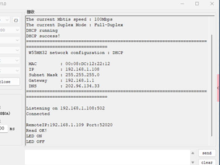
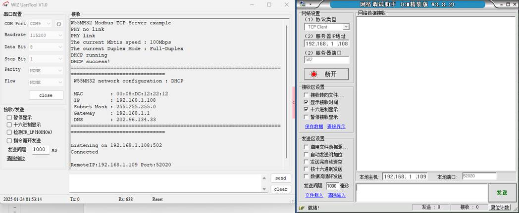
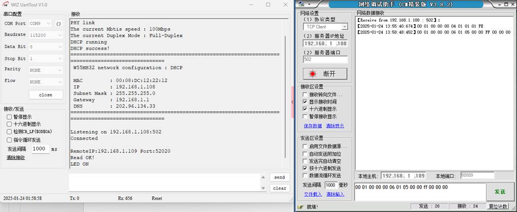
After the burning routine is executed, the first thing you will notice is that the PHY link detection has been carried out. Then, the set network address information is printed. Subsequently, the listening for addresses and port numbers begins. The information is shown in the following figure:
We use the network debugging assistant to establish the connection:
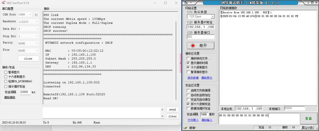
Then send the message "00 01 00 00 00 06 01 01 00 00 00 01" and reply with "0 01 00 00 00 04 01 01 01 FE" as shown in the following diagram:
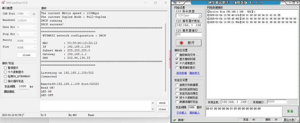
Then we sent the command "01 00 00 00 06 01 05 00 00 ff 00 00 00", and the LED was turned on. The command was also sent back.
Sending "0 01 00 00 00 06 01 05 00 00 00 00 00 00" will turn off the LED:
10 Summary
This article explains how to implement the Modbus TCP protocol server mode on the W55MH32 chip. Through practical examples, it demonstrates the complete process from initializing the related functions for LEDs, calling the main loop to handle functions, to parsing and processing the received messages. The article details the concept, basic principles, advantages, precautions, application scenarios, message structure, and common function codes of Modbus TCP, helping readers understand its practical application value in industrial communication.
The next article will explain how to implement HTTP_Server and NetBIOS functions on the W55MH32 chip, and will explain how to access the web content of the HTTP server through the NetBIOS name. It will also explain the specific implementation steps and key points through practical examples. Stay tuned!
WIZnet is a non-fabrication semiconductor company founded in 1998. Its products include the Internet processor iMCU™, which adopts TOE (TCP/IP Offloading Engine) technology and is based on a unique patented fully hardwired TCP/IP. iMCU™ is designed for embedded Internet devices in various applications.
WIZnet has over 70 distributors worldwide, with offices in Hong Kong, South Korea, and the United States, providing technical support and product marketing.
The region managed by the Hong Kong office includes: Australia, India, Turkey, and Asia (excluding South Korea and Japan).