
Function Comparison of CH394Q and W5500
1. Introduction to CH394Q:
The CH394 is an Ethernet protocol stack management chip used for Ethernet communication in microcontroller systems. The CH394 chip integrates a 10/100M Ethernet media transport layer (MAC) and physical layer (PHY), is fully compatible with the IEEE 802.3 protocol, and has built-in firmware for Ethernet protocol stacks such as IP, ARP, ICMP, IGMP, UDP, and TCP.
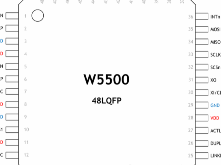
The following is a pin comparison diagram of the CH394Q and W5500 chips. The CH394Q and W5500 have the same package, and key pins such as the Ethernet port and crystal oscillator pin are fully compatible.
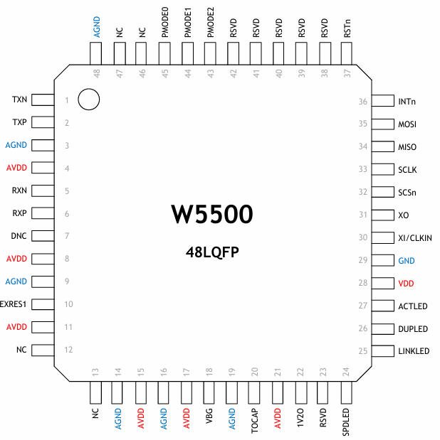
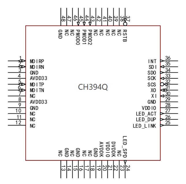
Pin configuration comparison chart of CH394Q and W5500
CH394Q | W5500 | |
Packaging | LQFP48 (7*7mm) | LQFP48 (7*7mm) |
2. Parameter Comparison between CH394Q and W5500
parameter | CH394Q | W5500 |
PHY | 100M/10M | 100M/10M |
Built-in TCP/IP protocol stack | √ | √ |
Network cable polarity MDI/MDIX | √ | X |
Built-in Ethernet 50Ω impedance matching resistor | √ | External |
Wake-on-LAN and Power Failure | √ | √ |
SPI interface | 62MHz (modes 0 and 3) | 33.3MHz (Modes 0 and 3) |
Number of Sockets and Cache | 8/32K | 8/32K |
MAC address | Factory-installed unique MAC address | Requires separate configuration or purchase |
100M communication current | 77mA | 132mA |
Interface voltage | 1.2V, 1.8V, 2.5V , 3.3V | 3.3V |
Operating temperature | -40-85℃ | -40-85℃ |
Note: Auto MDI/MDIX allows network devices to automatically identify crossover cables or straight-through cables and switch the wiring sequence without needing to pay attention to the physical wiring sequence.
3. Comparison of hardware circuit design between CH394Q and W5500
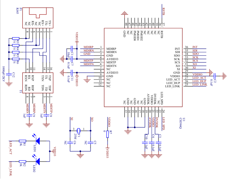
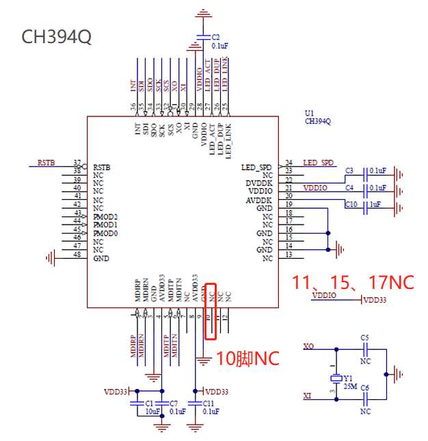
(1) CH394 schematic diagram
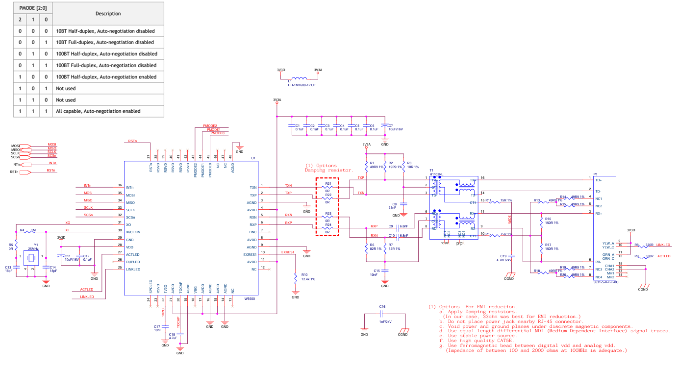
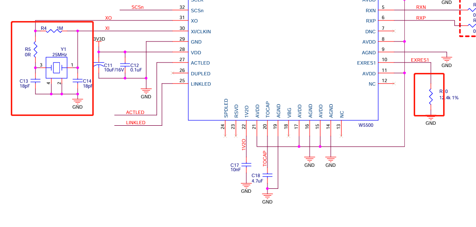
(2) W5500 schematic diagram
The CH394Q and W5500 have largely the same circuitry, but the CH394's external circuitry is more streamlined (the image below shows the CH394Q on the left and the W5500 on the right) . This should be considered when designing the circuit.
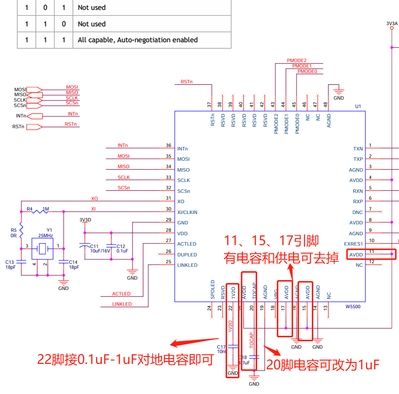
1. Power supply circuit:
(1) Pin 4 of CH394Q, VCC33, is the main power supply. The capacitor to ground should be placed close to the chip. It is recommended to use 0.1uF in parallel with 10uF or 4.7uF. The capacitor to ground for pin 8, VCC33, is recommended to be 1uF. The power supply voltage is 3.3V.
If there are capacitors and power supplies on pins 11, 15, and 17 of the original W5500 power supply, they can be removed.
(2) Connect an external capacitor to ground for pin 20 AVDDK and place it close to the chip. It is recommended to change it to 1uF.
(3) Connect an external capacitor to ground for pin 22 of the DVDDK and place it close to the chip. A range of 0.1uF to 1uF is recommended.
(4) The I/O pins of CH394 use VDDIO power supply. VDDIO supports 3.3V, 2.5V and 1.8V . An external 0.1uF capacitor to ground (in the range of 0.1uF to 1uF) is connected and placed close to the chip, allowing VDDIO to be directly connected to VCC33.
(5) The 10-pin resistor can be removed.
The above are all suggestions and do not need to be removed.
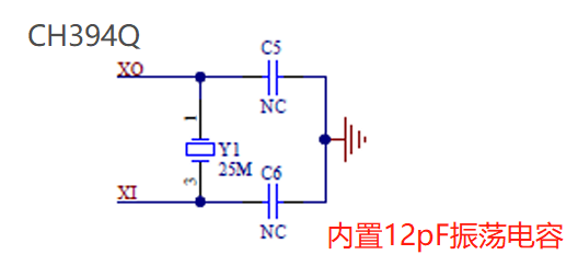
2. Crystal oscillator circuit:
- The CH394Q crystal oscillator has a built-in 12pF oscillation capacitor . If there is a resistor or capacitance to ground on pins 30 (XI) and 31 (XO), remove the resistor. The capacitor must be removed when the crystal load capacitance is 12pF (it is already built-in), and 15pF is recommended when the crystal load capacitance is 20pF.
- Network circuitry:
- Connect the Ethernet signal cable directly to the network transformer, without or removing the 49.9R or 50R resistor (built into the CH394Q) and the 10R pull-up resistor , and remove the parallel 82R resistor ; (this must be removed).
- The center tap of the network transformer is grounded through a capacitor of 0.01uF to 1uF , with 0.1uF or higher recommended. The center tap must not be connected to any power source . If a power source is connected, it must be disconnected and the resistor connected to the center tap of the network transformer removed.
- Shorting the two center taps and sharing a capacitor is a secondary option. If it is not possible to disconnect the center taps from the power supply, then the resistor connected in series on the Ethernet drive signal line should be replaced with a 10nF DC blocking capacitor, which can be selected from 4.7nF to 0.1uF.
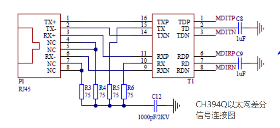
CH394Q network port section
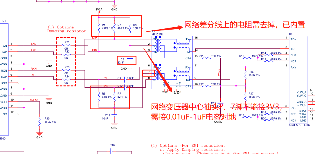
W5500 network port section