[Digi-Key Follow me Issue 4] Getting Started Tasks | Basic Task 1: Setting up the Environment and Pi
[Digi-Key Follow me Issue 4] Getting Started Tasks | Basic Task 1: Setting up the Environment and Pinging the Network

Target
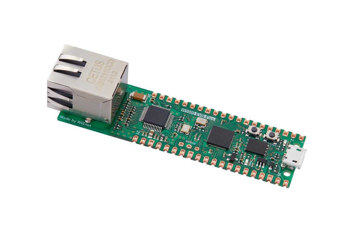
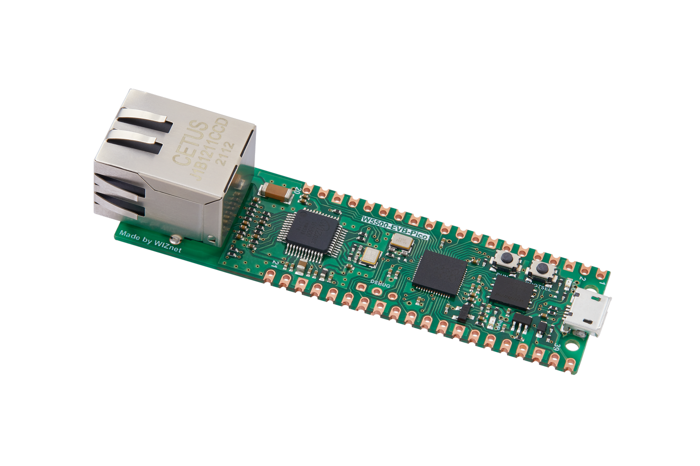
Build the development environment of RP2040 Pico + W5500 EVB Control the onboard LED to blink to confirm that the hardware is normal Initialize W5500, and confirm that the network connection is normal through the Ethernet Ping (Packet Internet Groper) command Capture packets through wireshark and analyze ICMP packets Theory ICMP packet frame structure: ICMP (Internet Control Message Protocol) is a network protocol that is used to transmit control information and error messages in IP networks. It is usually used with the IP protocol. The IP protocol is responsible for sending and routing data packets, while the ICMP protocol is responsible for checking whether the network is reachable, whether the route is correct, whether the host is reachable, and other network status feedback information. The main functions of the ICMP protocol are as follows: Discover network errors: When a data packet has an error during transmission, the ICMP protocol discovers network errors by sending an error notification to the sender. Check whether the network is reachable: By sending ICMP ECHO requests and receiving ICMP ECHO reply messages, you can determine whether the target host is reachable. Detect host errors: When a host fails to work properly, the ICMP protocol detects host errors by sending error notifications to the sender. Send routing information: The ICMP protocol can send routing information to other hosts to help them find appropriate routes in the network. Reference link For more information about the ping command, please refer to: ping command For more information about ICMP commands: Detailed analysis of ICMP commands Hardware
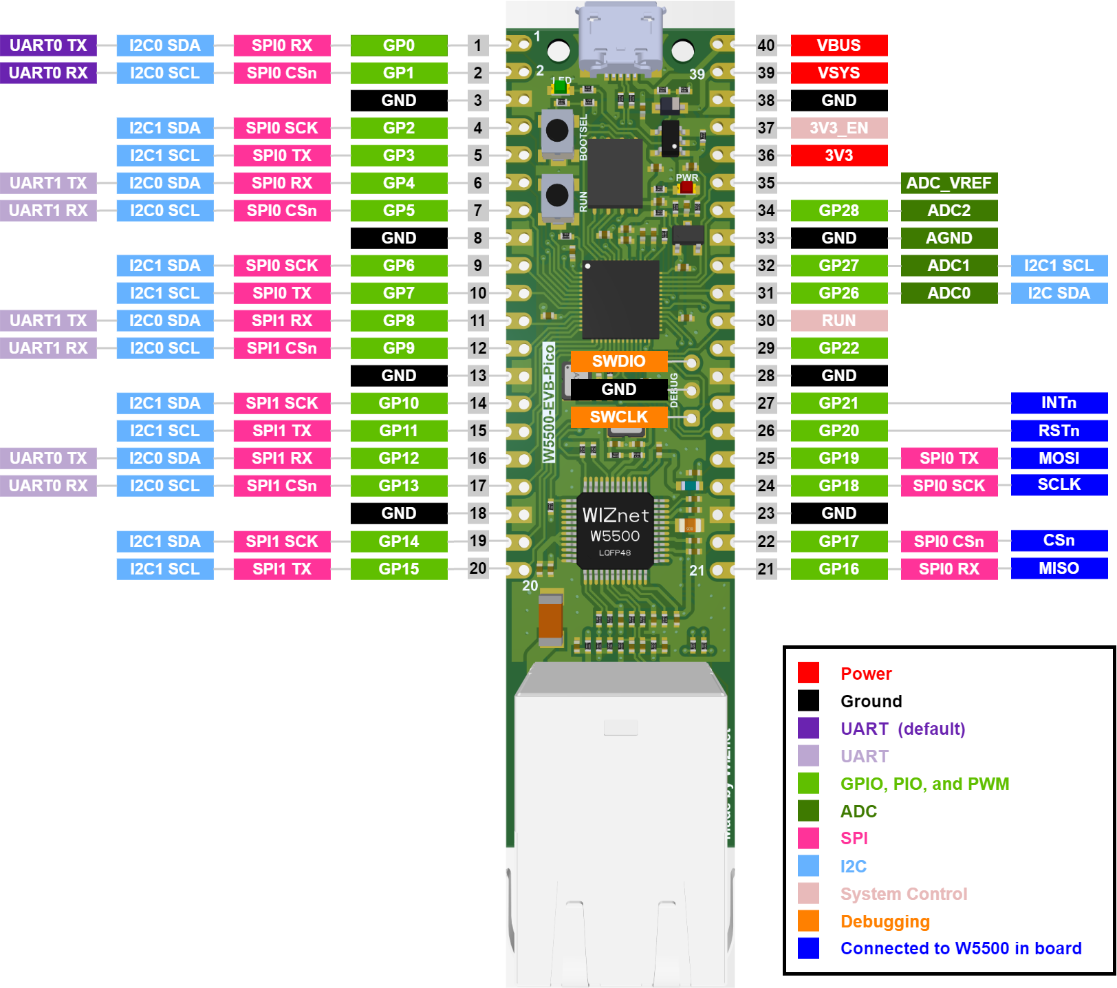
 At the same time, if you need to use SPI externally, try to avoid SPI multiplexing or mutual interference with the W5500 connection. Other notes: The learning video provided by EEWorld uses the W5500 Pico EVB to connect through a router or switch, and then uses a PC to test the network. Therefore, the Ethernet cable is connected with a straight line. If the W5500 development board is directly connected to the Ethernet port of the PC, a crossover cable is required. ps: Since this experiment was conducted during the holiday, there are no "high-end devices" such as routers/switches in my hometown, so the following experiments are all conducted using a PC and W5500 development link method. softwareBurning firmware
 Download the UF2 file from the following download link: adafruit-circuitpython-wiznet_w5500_evb_pico-en_GB-8.2.9.uf2.  Test LED Blink Use the simplest blinky program to test that the development environment and hardware are working properly. Copy
Ping network Refer to the lib file in the RP2040-HAT-CircuitPython example repository and import the W5500 library file into the development board.  Refer to the network ping test example in the RP2040-HAT-CircuitPython example repository for testing. Copy
Baidu cloud Ping the network


 Packet capture By capturing the packet as follows, you can see the ICMP data packet, and through the Type field, you can see the request packet and the response packet.  |


