
Detailed Explanation of Commonly Used Power Supply Communication Circuits
Detailed Explanation of Commonly Used Power Supply Communication Circuits
The sampling and PWM drive circuit principles of digital power supplies enable them to form an internal control loop. However, to achieve power supply control and management, a communication connection with the digital control core is still required. This article will guide you through the commonly used communication circuits in digital power supplies.
I. Commonly Used Communication Methods
As mentioned in the previous section on digital and analog power supplies, in order to better manage and control digital power supplies, they need to have communication capabilities.
Through host computer software, engineers can set power parameters and control power status. However, because the digital power supply control core outputs TTL levels, there are inconsistencies in level standards when communicating with peripheral devices. Therefore, a level conversion chip is needed to achieve data exchange between the two. Common communication methods in digital power supplies include RS485, RS232, CAN, TCP /IP, and I2C.
(a) Classification of communication methods

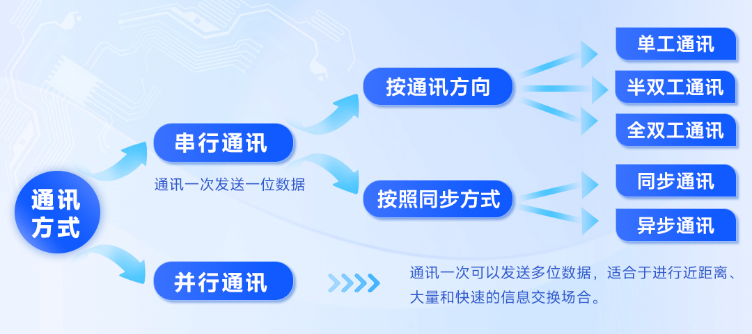
Communication methods are classified into serial communication and parallel communication according to the data transmission method.
Parallel communication: Transmits data in bytes or multiples of bytes. It is fast but expensive over long distances. It is suitable for short-distance, high-volume, and rapid information exchange scenarios.
Serial communication, also known as point-to-point communication, sends one bit of data at a time. It requires fewer lines, has low cost, is easy to expand, and is suitable for long-distance transmission. It is currently the most commonly used communication method.
According to different classification methods, serial communication can be divided into the following types:
1. According to the communication direction, it is divided into simplex communication, half-duplex communication and full-duplex communication.
①In simplex communication, information can only be transmitted in one direction, and the sending and receiving ends remain fixed.
② Half-duplex communication allows bidirectional transmission of information, but sending and receiving cannot occur simultaneously. The communication transceiver can be variable, such as a walkie-talkie, which is a typical half-duplex communication method.
③ Full-duplex communication allows data to be transmitted simultaneously in both directions. A transmitter and receiver are set up at each end, and two data lines are configured for signal transmission.
2. According to the data synchronization method, it can be divided into synchronous communication and asynchronous communication.
① Synchronous communication requires that the clock frequencies of the transmitting and receiving ends be consistent, and the information frame consists of synchronization characters, data characters, and check characters (CRC).
② In asynchronous communication, the clocks of the transmitting and receiving ends are not required to be synchronized. The transmission time interval is uncertain. When transmitting, start bits and stop bits should be added to the bytes so that the receiving end can receive the information correctly.
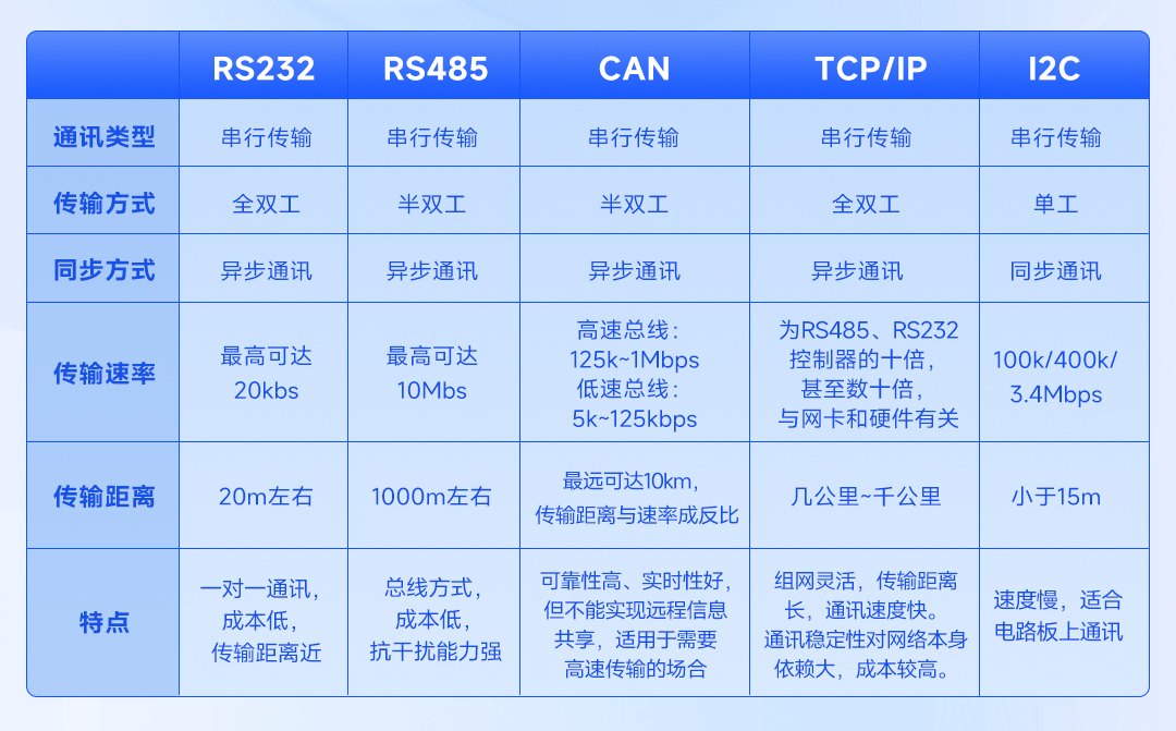
(II) Comparison of Communication Methods
This section compares commonly used communication methods in digital power supplies.

II. Introduction to Communication Circuits
(a) RS232
The RS-232 uses negative logic levels. The voltage range for "0" level is 3~15V, and the voltage range for "1" level is -15~-3V. The 9-pin interface is the mainstream interface form at present.
RS-232 level conversion circuits come in two types: isolated and non-isolated.
Non-isolated circuits can be implemented using transistors or non-isolated level shifting chips (such as Analog Devices' MAX232ESE, ADM232AARNZ, and TI 's MAX3232IDR). Isolated level shifting chips include RSM232, Analog Devices' ADM3251EARWZ, and Maxliner's SP3232EEY.
This article provides a typical transistor level conversion circuit and an interface connection circuit diagram for RSM232.
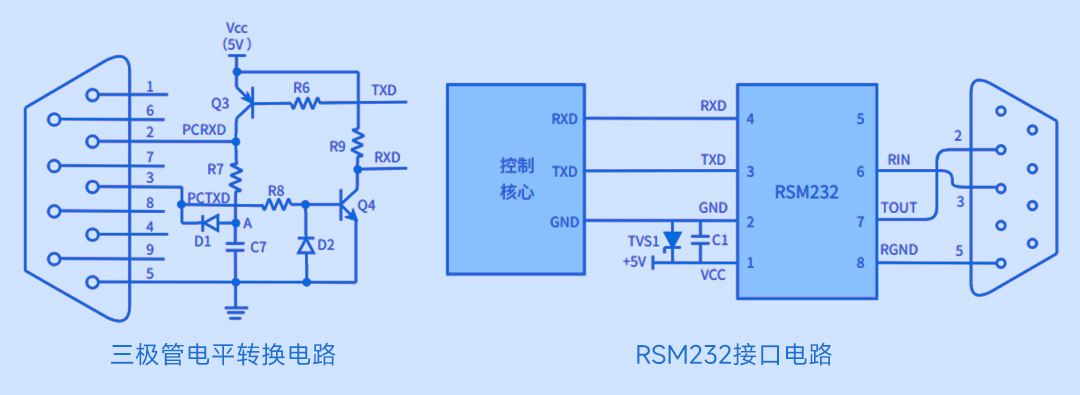

Analysis of the working principle of transistor level conversion circuit:
The voltage at point A is maintained between -3V and -15V through the action of diode D1 and capacitor C7.
When TXD=1, Q3 is cut off, the voltage of PCRXD is equal to the voltage of PCTXD, and PCRXD=1;
When TXD=0, Q3 is turned on, and the PCRXD voltage is approximately +5V, so PCRXD=0.
When PCTXD=1, Q4 is off, the RXD voltage is approximately 5V, and RXD=1;
When PCTXD=0, Q4 is turned on, the RXD voltage is 0, and RXD=0.
D2 is to prevent the BE of Q4 from being reversed and broken down.
(ii) RS485
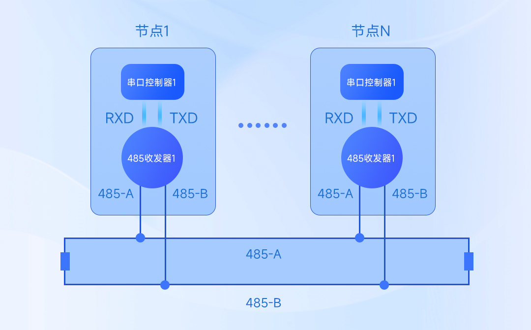
The RS-485 standard overcomes the shortcomings of RS-232 communication, such as short communication distance and low data rate. It uses differential transmission for data signals, resulting in strong anti-interference capabilities. RS-485 uses a pair of twisted-pair cables (A and B lines) for data transmission. A voltage difference between lines A and B within the range of -6 to -2V represents "0", and a voltage difference within the range of +2 to +6V represents "1". Furthermore, RS-485 requires a matching resistor at the far end of the transmission cable; its resistance should be equal to the characteristic impedance of the transmission cable. A connection diagram is shown below.

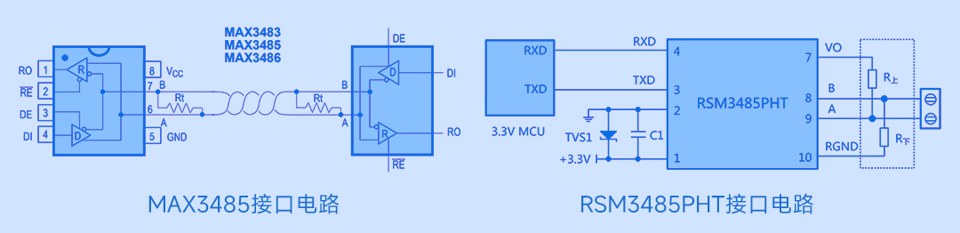
RS485 level conversion chips are divided into isolated and non-isolated types.
Typical non-isolated chips include MAX3485, ADI's MAX13487EESA+T, and TI's SN75176BDR; commonly used isolated chips include RSM3485PHT, TI's ISO3082DWR, and ISL32705E.

(III) CAN
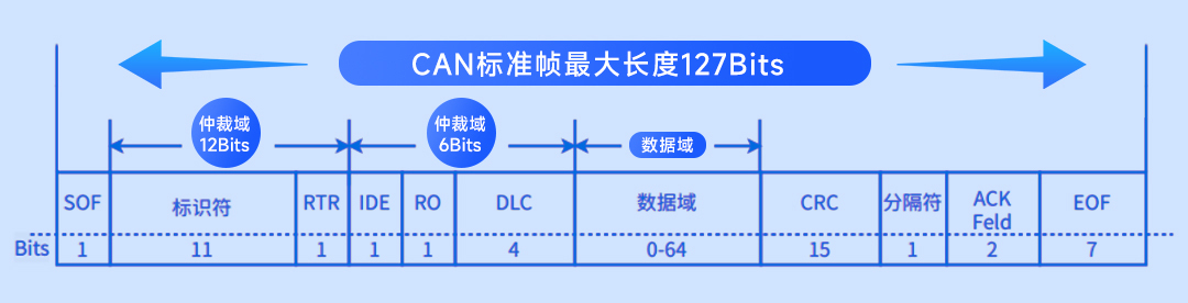
CAN bus communication uses differential signals for data transmission. The signal transmission lines are divided into CAN_H and CAN_L. A logic "0" on the bus indicates dominance, with a differential voltage difference of approximately 2V (CAN_H = 3.5V, CAN_L = 1.5V); a logic "1" indicates recession, with a differential voltage of 0V (CAN_H = 2.5V, CAN_L = 2.5V). CAN uses data frames for data transmission; the standard CAN data frame structure is shown in the figure below.

CAN communication interface circuits can be divided into two types: isolated and non-isolated.
Non-isolated circuits directly connect the CAN interface of the control core to the TX and RX pins of the driver IC, with no electrical isolation between nodes. To ensure the communication stability of the bus network, the CAN communication interface typically employs an isolated structure. Isolation circuits can be implemented using discrete components (such as optocouplers) or integrated devices (isolated CAN transceivers).
Commonly used CAN communication transceiver chips include NXP's TJA1050T, Microchip's MCP2551T, and TI's ISO1050.

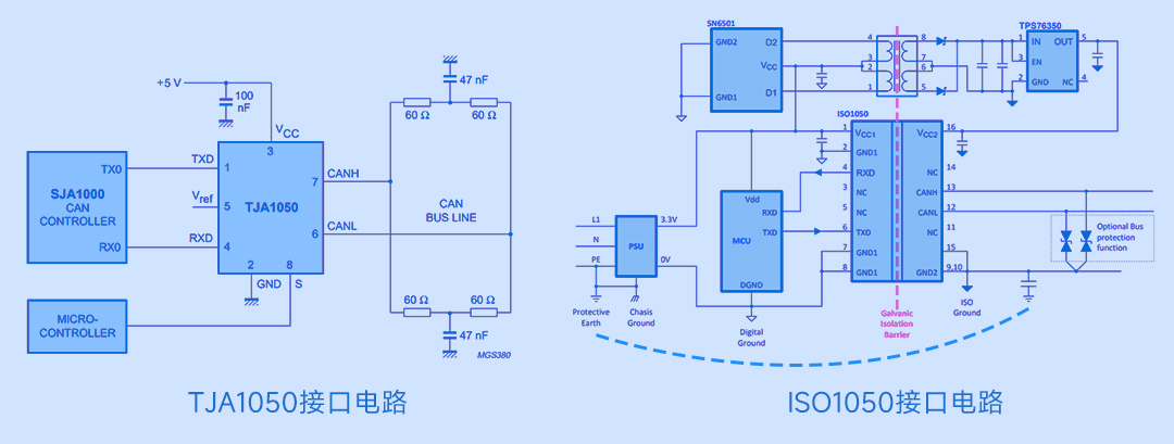
Taking ISO1050 as an example, the chip integrates an electrical isolation structure and uses an isolation transformer to isolate the power supplies Vcc1 and Vcc2 on both sides of the chip, ensuring that the chip can effectively isolate itself. A decoupling capacitor is connected between the chip's power supply and ground terminals to reduce interference, and a TVS diode is connected in parallel between the CAN_H and CAN_L terminals and ground for fast voltage protection.
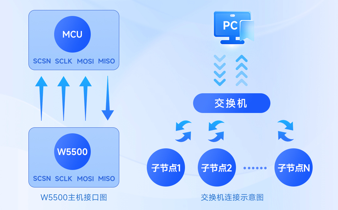
(iv) TCP/IP
The TCP/IP protocol is divided into four layers: the data link layer, the network layer, the transport layer, and the application layer.
The application layer includes protocols such as HTTP and FTP, while the transport layer includes TCP and UDP protocols. The network layer includes the IP protocol, which adds IP addresses and other data to the data to determine the transmission destination. The data link layer adds an Ethernet header to the data and performs CRC encoding, preparing for final data transmission.
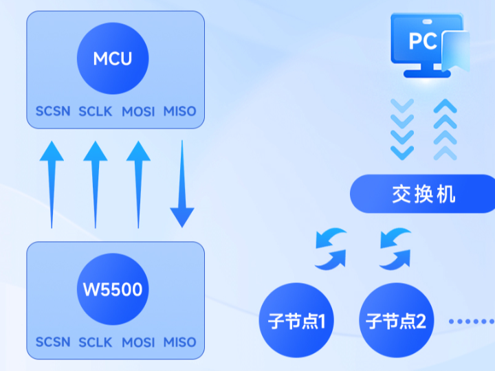
TCP/IP communication can be implemented using Ethernet protocol stack chips with embedded TCP/IP protocol (such as W5500, CH395, WT8266-S3) or by using a switch. Currently, the latter method is commonly used in digital power supplies.

This concludes the introduction to the communication principles and circuit implementation of commonly used communication methods in digital power supplies.