
Design and implementation of W55MH32 intelligent sensing door control
Design and implementation of W55MH32 intelligent sensing door control
1 Introduction
Infrared automatic door sensors are primarily used in public spaces and homes. When a person enters the sensing area, the door automatically opens or closes. When the sensor detects a person, it generates a pulse signal and transmits it to the main controller. The main controller uses this signal to determine whether the door needs to be opened or closed, thus enabling automatic door opening and closing. This system uses the W55MH32Q as the main control board and infrared sensors to achieve automatic door opening and closing (opening when someone enters and closing after a period of inactivity). It also supports button-activated door opening and closing, further enhancing its flexibility.
The W55MH32 is a high-performance Ethernet microcontroller from WIZnet. It utilizes a high-performance Arm® Cortex-M3 core with a maximum clock speed of 216MHz, along with 1024KB of internal Flash and 96KB of internal SRAM. Notably, it features the WIZnet TCP/IP Offload Engine (TOE), integrating a full hardware TCP/IP stack, MAC, and PHY. It also features a 32KB independent Ethernet transmit and receive buffer for eight hardware sockets, making it a true all-in-one solution.
2 Project Environment
2.1 Hardware Environment
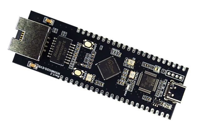
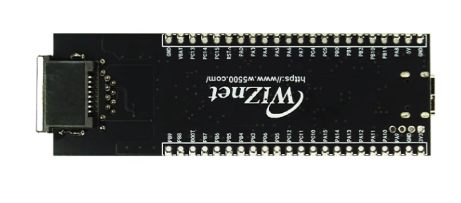
- W55MH32Q-EVB
- DuPont cables
- Infrared sensor, servo, buttons
2.2 Software Environment
- Keil uVision5
- WIZ UartTool V1.0 Serial Port Assistant
- Example Link: w5500.com/w55mh32.html
3. Hardware connection and solution
3.1 Solution Diagram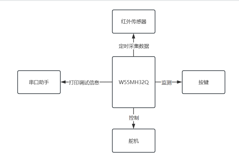
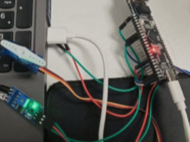
3.2 Hardware Connection
- Servo Signal Cable ---> W55MH32_GPIOA0
- Infrared Sensor OUT ---> W55MH32_GPIOA3
- Button ---> W55MH32_GPIOB1
4 Function Implementation
First, download the ADC routine from the official website of W55MH32, add and implement the code based on this routine, or choose other routines.
4.1 Add infrared detection code
Add infrared.c and its .h files to detect whether someone passes by. At the same time, this code implements the function of detecting when someone controls the servo to open and then waiting for a short time for the servo to close automatically. The specific code is as follows:
#include "adc.h"
#include "Timer.h"
#include "bsp_uart.h"
#include "infrared.h"
#include "w55mh32_gpio.h"
#include "w55mh32_rcc.h"
#include "servo.h"
#include <stdbool.h>
#include <stdio.h>
#include <string.h>
#include <stdint.h>


/**
* Static variables
*/
static bool s_delay_active = false; // Delay state flag (true=in delay phase)
static uint32_t s_delay_timer =
   0; // Delay timer (unit: ms, for 10-second delay logic)

/**
* @brief Initialize the infrared sensor (configure PA3 to analog input mode)
* @note The infrared sensor is connected to PA3 and multiplexed as ADC input channel 3
*/
void infrared_init(void) {
 GPIO_InitTypeDef gpio_init_structure;
 RCC_APB2PeriphClockCmd(RCC_APB2Periph_GPIOA, ENABLE); // Enable GPIOA clock

 //Configure PA3 as analog input (used to read the analog signal of the infrared sensor)
 gpio_init_structure.GPIO_Pin = GPIO_Pin_3;
 gpio_init_structure.GPIO_Mode = GPIO_Mode_AIN; // Analog input mode
 GPIO_Init(GPIOA, &gpio_init_structure);
}

/**
* @brief Get infrared sensor detection results (based on filtered AD values)
* @return 1-Object detected (AD value < 1500), 0-object not detected (AD value ≥ 1500)
* @note Depends on the filtering function of the ADC module (AD_FilterProcess), and the ADC must be initialized first
*/
uint16_t infrared_get_data(void) {
 uint16_t temp_data;
 uint16_t temp;

 ad_filter_process();           // Perform AD filtering to obtain a stable value
 temp = g_ad_filtered_value[0]; // Corresponding to the filtered value of ADC channel 0 of the infrared sensor

 // Determine whether an object is detected based on the threshold
 if (temp < 1500) {
   temp_data = 1; // Object detected
 } else {
   temp_data = 0; // No object detected
 }

 return temp_data;
}

/**
* @brief Read the raw AD value of the infrared sensor (unfiltered)
* @return Original AD sampling value (directly taken from ADC raw buffer)
*/
uint16_t infrared_read_raw(void) {
 return g_ad_value[0]; // Corresponding to the original value of ADC channel 0 of the infrared sensor
}

/**
* @brief Infrared sensor detection logic processing
* Function: Turn on the servo when an object is detected and start a 10-second timer; the servo will automatically turn off after 10 seconds
*/
void infrared_reaction(void) {
 uint16_t person_detected = infrared_get_data();

 // Start or reset a 10 second delay when an object is detected
 if (person_detected) {
   s_delay_active = true;       // Entering delayed state
        servo_set_angle(90);         // Turn on the servo
   s_delay_timer = 10000;       // Reset 10-second timer (10000ms)

 }
 // When no object is detected, the delay state is not intervened and the timer controls the shutdown
}
/**
* @brief TIM2 interrupt service function (triggered once every 1ms)
* Function: Process the 10-second delay countdown and turn off the servo after the end
*/
void TIM2_IRQHandler(void) {
 if (TIM_GetITStatus(TIM2, TIM_IT_Update) == SET) {
   // If in delay state and the timer has not ended, decrement the timer
   if (s_delay_active && s_delay_timer > 0) {
     s_delay_timer--;

     // When the timer ends, turn off the servo and exit the delay state
     if (s_delay_timer == 0) {
       s_delay_active = false;
       servo_set_angle(0); // 关闭舵机
     }
   }
   TIM_ClearITPendingBit(TIM2, TIM_IT_Update); // Clear interrupt flag
 }
}

#ifndef __INFRARED_H__
#define __INFRARED_H__
#include "delay.h"

/**
* @brief Initialize the infrared sensor (configure PA3 as analog input)
*/
void infrared_init(void);
uint16_t infrared_get_data(void);
uint16_t infrared_read_raw(void);
void infrared_reaction(void);

#endif // __INFRARED_H__
4.2 Adding some code for servo initialization
Add servo.c and its .h files to initialize the servo. The specific code is as follows:
#include "w55mh32_gpio.h"
/**
* @file servo.c
* @author []
* @brief Implementation file of servo PWM control function, including servo initialization, PWM setting and angle control
* @version 0.1
* @date [Modification date, such as 2025-08-18]
*
* @copyright [Copyright information, such as Copyright (c) 2025]
*/
/**
* @brief Servo PWM initialization function
* @note Configure the TIM5 timer to generate the PWM signal required for the servo drive (period 20ms, 50Hz)
* Output PWM through the PA0 pin to control the servo angle
* @param none
* @return none
*/
void servo_pwm_init(void)
{
// Enable TIM5 timer clock (APB1 bus) and GPIOA clock (APB2 bus)
RCC_APB1PeriphClockCmd(RCC_APB1Periph_TIM5, ENABLE);
RCC_APB2PeriphClockCmd(RCC_APB2Periph_GPIOA, ENABLE);
// Configure PA0 as multiplexed push-pull output (for PWM output of TIM5_CH1)
GPIO_InitTypeDef gpio_init_struct;
gpio_init_struct.GPIO_Mode = GPIO_Mode_AF_PP; // Multiplexed push-pull output
gpio_init_struct.GPIO_Pin = GPIO_Pin_0; // Configuring the PA0 pin
gpio_init_struct.GPIO_Speed = GPIO_Speed_50MHz; // Output speed 50MHz
GPIO_Init(GPIOA, &gpio_init_struct); // Apply configuration to GPIOA
// Configure TIM5 to use the internal clock source
TIM_InternalClockConfig(TIM5);
// Configure the TIM5 timer time base parameters
TIM_TimeBaseInitTypeDef tim_timebase_init_struct;
tim_timebase_init_struct.TIM_ClockDivision = TIM_CKD_DIV1; // Clock is not divided
tim_timebase_init_struct.TIM_CounterMode = TIM_CounterMode_Up; // Up counting mode
tim_timebase_init_struct.TIM_Period = 20000 - 1; // Automatic reload value (cycle 20ms)
tim_timebase_init_struct.TIM_Prescaler = 216 - 1; // Prescaler (216 division, counting frequency 1MHz)
tim_timebase_init_struct.TIM_RepetitionCounter = 0; // Repeat counter (not used)
TIM_TimeBaseInit(TIM5, &tim_timebase_init_struct); // Apply time base configuration
// Configure TIM5 channel 1 to PWM output mode
TIM_OCInitTypeDef tim_oc_init_struct;
TIM_OCStructInit(&tim_oc_init_struct); // Initialize the structure to default values
tim_oc_init_struct.TIM_OCMode = TIM_OCMode_PWM1; // PWM Mode 1
tim_oc_init_struct.TIM_OCPolarity = TIM_OCPolarity_High; // Output polarity high
tim_oc_init_struct.TIM_OutputState = TIM_OutputState_Enable; // Enable output
tim_oc_init_struct.TIM_Pulse = 0; // Initial pulse width 0
TIM_OC1Init(TIM5, &tim_oc_init_struct); // Apply configuration to channel 1
// Enable TIM5 timer
TIM_Cmd(TIM5, ENABLE);
}
/**
* @brief PWM Set Compare Register (CCR) Value
* @param compare The value of CCR to be written, range: 0~20000
* @return none
* @note CCR and ARR jointly determine the duty cycle, Duty = CCR / (ARR + 1)
* Input parameters will be checked to ensure they are within the valid range.
*/
void pwm_set_compare5(uint16_t compare)
{
// Make sure the input value is within the valid range
if (compare > 20000)
{
compare = 20000;
}
TIM_SetCompare1(TIM5, compare); // 设置CCR1的值(修正原代码中CCR2的错误)
}
/**
* @brief Servo setting angle
* @param angle The servo angle to be set, range: 0~180 degrees
* @return none
* @note Angle values will be limited to 0 or 180 degrees if they are out of range.
* Convert the angle to the corresponding PWM pulse width (500~2500us) through linear transformation
*/
void servo_set_angle(float angle)
{
uint16_t pulse_width;
// Limit the angle range to 0~180 degrees
if (angle < 0.0f)
{
angle = 0.0f;
}
else if (angle > 180.0f)
{
angle = 180.0f;
}
// Convert the angle linearly to the corresponding pulse width value (500~25020us)
pulse_width = (uint16_t)(angle / 180.0f * 2000.0f + 500.0f);
pwm_set_compare5(pulse_width);
}
#ifndef SERVO_H
#define SERVO_H
#include <stdint.h>
/**
* @brief Initialize the PWM timer and GPIO pins required for servo driving
*
* This function is used to enable the TIM5 timer and GPIOA clock, configure GPIOA_PIN_0 as a multiplexed push-pull output,
* And initialize TIM5 to PWM1 mode to generate the PWM signal required for servo drive.
* @return No return value
*/
void servo_pwm_init(void);
void pwm_set_compare5(uint16_t compare);
void servo_set_angle(float angle);
#endif // SERVO_H4.3 Adding code for key control of servos
Add key.c and its .h files to control the servo to turn on by pressing a button, and the servo will automatically turn off after a period of time. The specific code is as follows:
#include "delay.h"
#include "servo.h"
#include "w55mh32_gpio.h"
#include <stdbool.h>

static bool s_delay_active = false; // Delay state flag (true=in delay phase)
static uint32_t s_delay_timer = 0;

/**
* @brief  Button initialization function
* @note   Configure the GPIOB pin to pull-up input mode to detect key input
* @param  无
* @return 无
*/
void key_init(void) {
 // Enable GPIOB port clock
 RCC_APB2PeriphClockCmd(RCC_APB2Periph_GPIOB, ENABLE);

 // Define GPIO initialization structure
 GPIO_InitTypeDef GPIO_InitStructure;
 GPIO_InitStructure.GPIO_Mode = GPIO_Mode_IPU; // Pull-up input mode
 GPIO_InitStructure.GPIO_Pin = GPIO_Pin_1;     // Configuring the PB1 pin
 GPIO_InitStructure.GPIO_Speed =
     GPIO_Speed_50MHz; // Output speed 50MHz (this parameter has no effect in input mode)
 GPIO_Init(GPIOB, &GPIO_InitStructure); // Apply configuration to GPIOB
}

/**
* @brief  Press a key to get the key code function
* @note   Blocking operation, by detecting the PB1 pin level to determine whether the button is pressed, including debounce processing
* @param none
* @return The key code value of the pressed button: 0 (no button is pressed), 1 (the button corresponding to PB1 is pressed)
* @attention When the button is pressed, the function will block until the button is released.
*/
uint8_t key_getnum(void) {
 uint8_t keynum = 0;

 //
 if (GPIO_ReadInputDataBit(GPIOB, GPIO_Pin_1) == 0) {
   delay_ms(20); // Delay debounce

   // Wait for the button to be released
   while (GPIO_ReadInputDataBit(GPIOB, GPIO_Pin_1) == 0)
     ;

   delay_ms(20); // Delay debounce
   keynum = 1;   // Mark PB1 button is pressed
 }

 return keynum;
}

/**
* @brief Key response processing function
* @details Control the servo angle according to the button status to achieve mechanical response of button triggering
* @param none
* @return none
*/
void key_reaction(void) {
 uint16_t key_num = key_getnum();

 /* Set the corresponding servo angle according to the button number */
  if (key_num == 1) {
   s_delay_active = true;       // 进入延迟状态
        servo_set_angle(90);         // 打开舵机
   s_delay_timer = 10000;       // 重置10秒计时(10000ms)
 }
}
void TIM4_IRQHandler(void) {
 if (TIM_GetITStatus(TIM4, TIM_IT_Update) == SET) {
   // If in delay state and the timer has not ended, decrement the timer
   if (s_delay_active && s_delay_timer > 0) {
     s_delay_timer--;

     // When the timer ends, turn off the servo and exit the delay state
     if (s_delay_timer == 0) {
       s_delay_active = false;
       servo_set_angle(0); // Turn off the servo
     }
   }
   TIM_ClearITPendingBit(TIM4, TIM_IT_Update); // Clear interrupt flag
 }
}
#ifndef KEY_H
#define KEY_H

#include <stdint.h>

void key_init(void);
uint8_t key_getnum(void);
void key_reaction(void);
#endif // __KEY_H__
5 Functional Verification
When the infrared sensor detects an obstruction, it controls the servo to turn on and off after a period of time.
The servo can be manually turned on and off by pressing a button.
6. Conclusion
This article details the design and implementation of an infrared door control system. It uses infrared sensors to automatically open and close doors, while also enabling push-button control. Thank you for your patience! If you have any questions or would like to learn more about this product and its applications, please feel free to leave a message via private message or in the comments section. We will respond as soon as possible and provide more detailed answers and assistance!
————————————————
Copyright Notice: This article is original and is licensed under the CC 4.0 BY-SA license. Please include the original source link and this notice when reposting.
Original Link: https://blog.csdn.net/2301_81684513/article/details/150847078