
Chapter 9: W55MH32’s RCC - Using HSE/HSI Clock Configuration
Chapter 9: W55MH32’s RCC - Using HSE/HSI Clock Configuration
Chapter 9: W55MH32’s RCC - Using HSE/HSI Clock Configuration
References for this chapter: "W55MH32 Reference Manual" - RCC section.
When studying this chapter, it is more effective to read it in conjunction with the RCC section of the "W55MH32 Reference Manual", especially for the parts related to register explanations.
RCC: reset clock control - reset and clock controller. In this chapter, we mainly explain the clock section, and it is particularly important to focus on understanding the clock tree. Once you understand the clock tree, you will have a thorough understanding of all the clock-related processes of the W55MH32.
1 The main function of RCC - the clock section
Set the system clock SYSCLK, set the AHB prescaler factor (determine how much HCLK is) , set the APB2 prescaler factor (determine how much PCLK2 is), set the APB1 prescaler factor (determine how much PCLK1 is), and set the prescaler factors of each peripheral; control the activation of the AHB, APB2 and APB1 bus clocks, and control the activation of each peripheral clock. For the configuration of these four clocks (SYSCLK, HCLK, PCLK2, PCLK1), it is usually: PCLK2 = HCLK = SYSCLK = PLLCLK = 72M, PCLK1 = HCLK/2 = 36M. This clock configuration is the standard configuration of the library function, and the one we use most is this.
2 RCC Block Diagram Analysis - Clock Section
1. When HSI is used as the input for the PLL clock, the maximum frequency of the system clock can reach 108 MHz.
2. For the characteristics of the internal and external clock sources, please refer to the "Electrical Characteristics" section in the corresponding product data sheet.
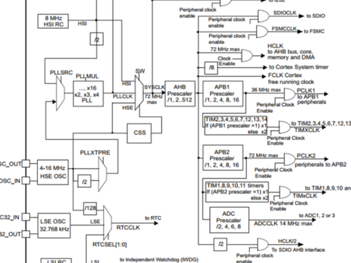
The user can configure the frequencies of the AHB, high-speed APB (APB2), and low-speed APB (APB1) domains through multiple prescalers. The maximum frequency of the AHB and APB2 domains is 216 MHz. The maximum allowable frequency of the APB1 domain is 108 MHz. The clock frequency of the SDIO interface is fixed at HCLK/2. The RCC, after being divided by 8 by the AHB clock (HCLK), serves as the external clock for the Cortex system timer (SysTick). By setting the control and status registers of SysTick, one can select either the above clock or the Cortex (HCLK) clock as the SysTick clock. The ADC clock is obtained from the high-speed APB2 clock after being divided by 2, 4, 6, or 8.
The frequency allocation of the timer clock is automatically set by the hardware in the following 2 cases:
1. If the corresponding APB prescaler coefficient is 1, the clock frequency of the timer is consistent with the frequency of the associated APB bus.
2. Otherwise, the clock frequency of the timer is set to twice the frequency of the connected APB bus.
FCLK is the free-running clock of Cortex™-M3. Details can be found in ARM's Cortex™-M3 Technical Reference Manual. The RCC clock tree is as follows:
2.1 System clock
2.1.1 HSE high-speed external clock signal
HSE is a high-speed external clock signal, which can be provided by an active crystal oscillator or a passive crystal oscillator. Its frequency ranges from 4 to 16 MHz. When using an active crystal oscillator, the clock enters through the OSC_IN pin and the OSC_OUT pin is left floating. When using a passive crystal oscillator, the clock enters through both OSC_IN and OSC_OUT pins, and a resonant capacitor needs to be matched.
The most commonly used HSE is the 8 MHz passive crystal oscillator. When determining the PLL clock source, HSE can either not be frequency-divided or divided by 2. This is set by the bit 17:PLLXTPRE of the clock configuration register CFGR. We set it to HSE without frequency division.
PLL clock source
The internal PLL can be used to multiply the output clock of HSIRC or the HSE crystal output clock. Refer to Figure 7 and the clock control registers.
The settings of the PLL (selecting the HIS oscillator divided by 2 or the HSE oscillator as the input clock of the PLL, and selecting the multiplication factor) must be completed before it is activated. Once the PLL is activated, these parameters cannot be changed.
If the PLL interruption is allowed in the clock interruption register, when the PLL is ready, an interrupt request can be generated.
If the USB interface needs to be used in the application, the PLL must be set to output a 48 or 72 MHz clock for providing the 48 MHz USBCLK clock.
PLL clock: PLLCLK
By setting the frequency multiplier of the PLL, the clock source of the PLL can be multiplied. The frequency multipliers can be: [2, 3, 4, 5, 6, 7, 8, 9, 10, 11, 12, 13, 14, 15, 16]. The specific setting is determined by the bit 21-18 of the clock configuration register CFGR: PLLMUL[3:0]. Here, we set it to a 9x frequency multiplication because in the previous step, we set the clock source of the PLL to HSE = 8M. After the PLL multiplication, the PLL clock: PLLCLK = 8M * 9 = 72M. 72M is the officially recommended stable operating clock by ST. If you want to overclock, you can increase the frequency multiplier. The maximum is 128M. Here, we set the PLL clock: PLLCLK = 8M * 9 = 72M.
System Clock (SYSCLK) selection
After the system is reset, the HSI oscillator is selected as the system clock. When a clock source is directly or indirectly used as the system clock (either through a PLL or otherwise), it cannot be stopped.
Only when the target clock source is ready (after a delay during the startup stabilization phase or PLL stabilization), will the switching from one clock source to another occur. The switching of the system clock will not happen until the selected clock source is ready. The switching occurs only when the target clock source is ready.
The status bits in the clock control register (RCC_CR) indicate which clock is ready and which one is currently being used as the system clock.
AHB bus clock HCLK
The system clock SYSCLK is divided by the AHB prescaler to obtain the clock called APB bus clock, namely HCLK. The division factor can be: [1, 2, 4, 8, 16, 64, 128, 256, 512]. The specific value is set by the bit 7-4 of the clock configuration register CFGR: HPRE[3:0]. The clocks of most external peripherals on the chip are obtained by dividing HCLK. As for the clock of the peripherals on the AHB bus, it will be set when we use the peripheral. Here, we only need to roughly set the APB clock.
APB2 bus clock PCLK2
The APB2 bus clock PCLK2 is obtained from HCLK through a high-speed APB2 prescaler. The division factor can be: [1, 2, 4, 8, 16]. This is determined by the bits 13-11 of the clock configuration register CFGR: PPRE2[2:0]. PCLK2 is a high-speed bus clock. All the high-speed external peripherals on the chip are connected to this bus, such as all GPIO, USART1, SPI1, etc. As for the clock setting of the external peripherals on the APB2 bus, it will be set when we use the peripheral. Here, we only need to roughly set the clock of APB2.
APB1 bus clock PCLK1
The APB1 bus clock PCLK1 is obtained from HCLK through a low-speed APB prescaler. The division factor can be: [1, 2, 4, 8, 16]. The specific value is determined by the bits 10-8: PRRE1[2:0] in the clock configuration register CFGR. PCLK1 is a low-speed bus clock with a maximum frequency of 36 MHz. The low-speed external peripherals on the chip are connected to this bus, such as USART2/3/4/5, SPI2/3, I2C1/2, etc. As for the clock setting of the peripherals on the APB1 bus, it will be set when we use the peripheral. Here, we only need to roughly set the clock of APB1.
2.1.2 Set system clock library function
The corresponding system clock configuration functions for the above 7 steps are as follows. This function is taken from the firmware library file "system_w55mh32.c". For easier reading, I have removed the code related to the interconnection, translated the English comments into Chinese, and numbered the code. There are a total of 7 steps. This function directly operates the registers. For the register part, please refer to the RCC register description section in the data manual.
Code listing: RCC-1 Function for setting the system clock library.
static void SetSysClockTo72(void)2.2 Other clocks
By explaining the settings of the system clock, we have already grasped about 60-70% of the entire clock tree. For the remaining clocks, we will explain a few important parts.
2.2.1 USB Clock
The USB clock is obtained by passing PLLCLK through the USB prescaler. The division factor can be [1, 1.5]. The specific value is determined by the bit 22:USBPRE in the clock configuration register CFGR. The maximum clock frequency of USB is 48M. By reversing the calculation based on the division factor, PLLCLK can only be 48M or 72M. Generally, we set PLLCLK to 72M and USBCLK to 48M. USB has strict requirements for the clock, so PLLCLK can only be obtained by multiplying HSE, and cannot use HSI for multiplication.
2.2.2 Cortex system clock
The Cortex system clock is obtained by dividing the HCLK by 8, and it is equal to 9 MHz. The Cortex system clock is used to drive the system timer SysTick of the core. SysTick is generally used for the clock ticks of the operating system and can also be used for ordinary timing.
2.2.3 ADC clock
The ADC clock is obtained by dividing PCLK2 through the ADC pre-divider. The division factor can be [2, 4, 6, 8]. The specific value is determined by the bits 15-14 of the clock configuration register CFGR: ADCPRE[1:0]. Surprisingly, there is no 1x division. The maximum ADC clock frequency can be 14 MHz. If the sampling period is set to the shortest 1.5 clock cycles, the ADC conversion time can reach the shortest 1 us. If the goal is to achieve the shortest conversion time of 1 us, then the ADC clock must be 14 MHz. Consequently, the PCLK2 clock can only be 28 MHz, 56 MHz, 84 MHz, or 112 MHz.
2.2.4 RTC clock, independent watchdog clock
The RTC clock can be obtained by dividing the HSE/128, or it can be provided by the low-speed external clock signal LSE. Its frequency is 32.768 KHZ. It can also be provided by the low-speed internal clock signal LSI. The specific choice of which clock is determined by the bit 9-8: RTCSEL[1:0] of the backup domain control register BDCR. The clock for the independent watchdog is provided by LSI, and it can only be provided by LSI. LSI is a low-speed internal clock signal with frequencies ranging from 30 to 60 KHZ, and typically 40 KHZ is chosen.
2.2.5 MCO clock output
MCO is the abbreviation of "microcontroller clock output", which is the clock output pin of a microcontroller. In the W55MH32 series, it is obtained by multiplexing PA8. Its main function is to provide an external clock, equivalent to an active crystal oscillator. The clock source of MCO can be: PLLCLK/2, HSI, HSE, SYSCLK. The specific selection is determined by the bit 26-24 of the clock configuration register CFGR: MCO[2:0]. Besides providing an external clock, we can also monitor the clock output of the MCO pin using an oscilloscope to verify whether the system clock configuration is correct.
3 Clock configuration
3.1 RCC_HSIConfig
1. The header file contains global definitions.
#include <stdlib.h>Header file: Includes standard libraries and hardware-related header files (w55mh32.h), delay functions (delay.h), and custom hardware abstraction layer (wiz.h).
Global variable: Defines the pointer USART_TEST of the serial port peripheral, which points to USART1.
2. Function declaration
void UART_Configuration(uint32_t bound);UART_Configuration:Configure serial port communication.
RCC_ClkConfiguration:Configure the system clock (RCC, reset and clock control).
3. main() function: System initialization and main logic
int main(void)Function:
● Initialize the system clock (HSI + PLL).
● Initialize the serial port and output clock frequency information through printf.
● Enter an infinite loop. The program has no actual business logic; it only verifies the clock and serial port configurations.
4. RCC_ClkConfiguration() Function: System Clock Configuration
void RCC_ClkConfiguration(void)Clock configuration process:
(1) Reset RCC: Reset all clock configurations.
(2) Enable HSI: Use the internal 16MHz clock.
(3) Configure PLL: Input: HSI/2 = 8MHz.
(4) Output: 8MHz × 32 = 256MHz (System Clock SYSCLK).
(5) Select PLL as the system clock source.
(6) Bus division:
a. HCLK (AHB bus): 256MHz (no division).
b. PCLK1 (APB1 bus): 128MHz (HCLK/2).
c. PCLK2 (APB2 bus): 256MHz (no division).
(7) Enable LSI: For independent watchdog or RTC (not used in the code).
- Redundant operation: Repeat enabling HSI (has no practical significance, HSI is already ready).
Note:
● The output frequency of the PLL must comply with the specifications of the chip (for example, the maximum SYSCLK of W55MH32 is 256MHz).
● WIZ_RCC_PLLConfig () is a custom function (from wiz.h) used to extend the PLL configuration.
5. UART_Configuration() Function: Serial Port Initialization
void UART_Configuration(uint32_t bound)Function:
● Enable the clock for USART1 and GPIOA.
● Configure PA9 (TX) as a re-mapped push-pull output, and PA10 (RX) as an open-drain input.
● Initialize the serial port parameters (baud rate, data bits, stop bits, etc.).
● Enable the serial port.
6. Serial output function
int SER_PutChar(int ch) Core functions:
● System clock configuration:
Use HSI (16MHz) as the PLL input, with PLL multiplication factor of 32, generating a 256MHz system clock.
Bus division: HCLK = 256MHz, PCLK1 = 128MHz, PCLK2 = 256MHz.
● Serial communication: Configure USART1 to a baud rate of 115200 for printf output.
● Test verification: Print the frequencies of all system clocks to verify the correctness of the clock configuration.
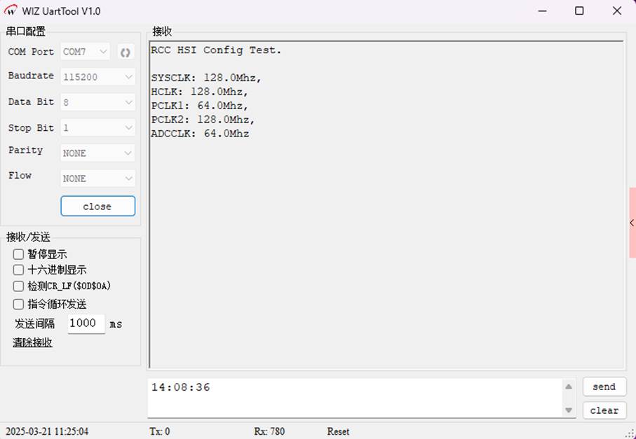
3.1.1 Experimental phenomenon
Download the compiled program to the development board, and you can see that different system clocks can be set.
3.2 RCC_HighFrequencyConfig
Program Execution:
1. Header Files and Global Variables
Standard library header files as well as custom header files delay.h, w55mh32.h, and wiz.h were included to provide the necessary functions and data types for the program.
Global variable USART_TEST was defined and pointed to USART1, which is used for subsequent serial communication operations.
2. Function Declarations
The functions UART_Configuration() and RCC_ClkConfiguration() were declared. The former is used to configure the serial port, and the latter is used to configure the system clock.
Main Function main():
int main(void)After initialization is completed, the printf() function is used to print out the frequency information of the system clock, AHB bus clock, APB1 bus clock, APB2 bus clock, and ADC clock. Then, an infinite loop is entered to make the program run continuously.
4. The main flow of the RCC_ClkConfiguration() function:
(1) Reset the RCC registers to prepare for the subsequent clock configuration.
(2) Enable the external high-speed clock (HSE) and wait for it to stabilize.
(3) Disable the PLL, reconfigure the clock source and multiplication factor of the PLL.
(4) Enable the PLL and wait for it to stabilize.
(5) Set the system clock source to the PLL output.
(6) Configure the clock division coefficients of the AHB, APB1, and APB2 buses.
(7) Enable the internal low-speed clock (LSI) and the internal high-speed clock (HSI), and wait for them to stabilize.
5. The UART_Configuration() function
(1) Enable the clocks of USART1 and GPIOA.
(2) Configure the transmit pin (PA9) of USART1 to be a push-pull output mode, and the receive pin (PA10) to be a floating input mode.
(3) Configure the parameters of USART1 such as baud rate, data bits, stop bits, parity bits, etc. Enable USART1.
6. The SER_PutChar() function: This function is used to send a character to the serial port and waits for the transmission to complete before sending the next character.
7. The fputc() function: Redirects the standard output function and sends characters to the serial port. If a newline character \n is encountered, it will first send a carriage return character \r.
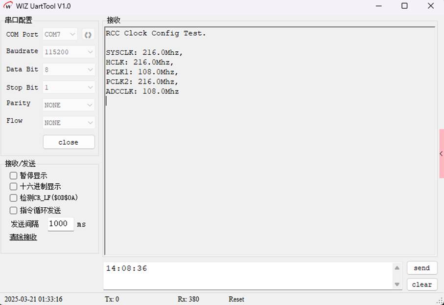
3.2.1 Experimental phenomenon
WIZnet is a fabless semiconductor company founded in 1998. Its products include the Internet processor iMCU™, which utilizes TOE (TCP/IP Offload Engine) technology and is based on a unique patented fully hardwired TCP/IP. The iMCU™ is designed for embedded Internet devices in various applications.
WIZnet has more than 70 distributors globally and has offices in Hong Kong, South Korea, and the United States, providing technical support and product marketing services.
The regions managed by the Hong Kong office include Australia, India, Turkey, and Asia (excluding South Korea and Japan).