
Chapter 8: Detailed Explanation of W55MH32 Startup Files
Chapter 8: Detailed Explanation of W55MH32 Startup Files
Chapter 8: Detailed Explanation of W55MH32 Startup Files
The reference materials for this chapter are "W55MH32 Reference Manual" Chapter 8 - Interrupts and Events, and the help manual in MDK - ARM Development Tools: used to query ARM's assembly instructions and compiler-related instructions.
1 Introduction to the Startup File
The startup file is written in assembly language and is the first program executed after the system powers on and resets. Its main tasks include:
1. Initialize the stack pointer SP to _initial_sp.
2. Set the PC pointer to Reset_Handler.
3. Initialize the interrupt vector table.
4. Configure the system clock.
5. Call the C library function _main to initialize the user stack, thereby eventually calling the main function to enter the C world.
2 Search for ARM assembly instructions
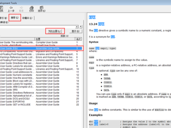
When explaining the startup code, we will encounter ARM assembly instructions and Cortex core instructions. Regarding the Cortex core instructions, we can refer to Chapter 4: Instruction Set in the "CM3 Official Guide CnR2". For the remaining ARM assembly instructions, we can search for them in MDK -> Help -> Uvision Help. Take EQU as an example, the search result is as follows:
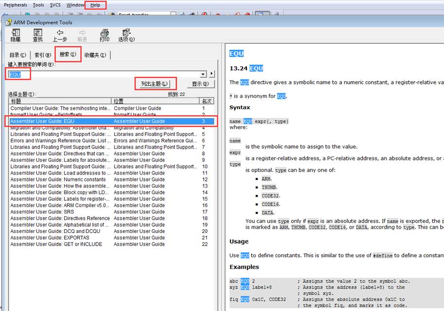
The retrieved results will be numerous. We only need to look at the "Assembler User Guide" section. The following lists the ARM assembly instructions used in the startup file. All the instructions in this list were retrieved from the "ARM Development Tools" help document. The compiler-related instructions WEAK and ALIGN have also been placed in the same table for convenience.
Instruction Name | Function |
EQU | Assigning a symbol name to a numeric constant is equivalent to the "define" statement in C language. |
AREA | Assemble a new code segment or data segment |
SPACE | Allocate memory space |
PRESERVE | The current file stack needs to be aligned at 8-byte intervals. |
EXPORT | Declare that a label has a global attribute and can be used by external files. |
DCD | Allocate memory in units of bytes, requiring 4-byte alignment, and initialize these memory areas |
PROC | Define subroutine, used in pairs with ENDP, indicating the end of the subroutine |
WEAK | Weak definition: If an external file declares a label, it will be used first. If no definition is provided, there will be no error (non-ARM instructions, belonging to the compiler function) |
IMPORT | The declaration labels are derived from an external file, similar to the EXTERN keyword in C language. |
B | Jump to a label |
ALIGN | The compiler aligns instructions/data addresses, often in conjunction with immediate values. The default alignment is 4 bytes (not for ARM instructions, but a feature of the compiler). |
END | Indicates the end of the file |
IF,ELSE,ENDIF | Assembly conditional branch statement, similar to the "if else" in C language. |
3 Explanation of Startup File Code
3.1 Stack - Stack
Stack_Size EQU 0x00000400The size of the allocated stack is 0X00000400 (1KB), named STACK, NOINIT means no initialization, read-write, 8 (2^3) bytes alignment. The stack is used for local variables, function calls, function parameters, etc. The size of the stack cannot exceed the size of the internal SRAM.
If the program being written is large and there are many local variables defined, then the size of the stack needs to be modified. If one day, your program has some inexplicable strange errors and enters a hard fault, at this time, you need to consider whether the stack is not large enough and has overflowed.
EQU: A macro definition pseudo-instruction, equivalent to equal, similar to C's define.
AREA: Tells the assembler to assemble a new code segment or data segment. STACK represents the segment name, which can be named arbitrarily; NOINIT indicates no initialization; READWRITE indicates read-write, ALIGN=3 means aligned by 2^3, that is, 8-byte alignment.
SPACE: Used to allocate a certain size of memory space, in bytes. Here, the specified size is equal to Stack_Size.
The label __initial_sp is placed immediately after the SPACE statement, indicating the end address of the stack, that is, the top address of the stack. The stack grows from high to low.
3.2 Heap
Heap_Size EQU 0x00000200The size of the allocated heap is 0X00000200 (512 bytes), named HEAP, NOINIT means no initialization, readable and writable, 8 (2^3) bytes aligned. __heap_base represents the starting address of the heap, and __heap_limit represents the ending address of the heap. The heap grows from low to high, opposite to the growth direction of the stack.
The heap is mainly used for dynamic memory allocation. Memory allocated by functions like malloc() is on the heap. This is less used in W5MH32.
PRESERVE8PRESERVE8: Specifies that the stack of the current file is aligned in 8-byte increments.
THUMB: Indicates that the subsequent instructions are compatible with THUMB instructions. THUMBM was the previous instruction set of ARM. It was 16-bit. Now, all the Cortex-M series use the THUMB-2 instruction set. THUMB-2 is 32-bit and is compatible with both 16-bit and 32-bit instructions. It is a superset of THUMB.
3.3 Vector Table
AREA RESET, DATA, READONLYDefine a data segment named "RESET", which is readable. And declare the three labels "__Vectors", "__Vectors_End" and "__Vectors_Size" as having global attributes, so that they can be called by external files.
EXPORT: Declares that a label can be used by external files, thereby giving the label a global attribute. If using the IAR compiler, the instruction used is GLOBAL.
When the kernel responds to an occurred exception, the corresponding exception service routine (ESR) will be executed. To determine the entry address of the ESR, the kernel uses the "vector table lookup mechanism". Here, a vector table is used. A vector table is actually an array of WORDs (32-bit integers), and each index corresponds to an exception. The value of the element at that index is the entry address of the corresponding ESR. The position of the vector table in the address space can be set, and it is indicated by a relocation register in the NVIC. After reset, the value of this register is 0. Therefore, a vector table must be present at address 0 (i.e., the FLASH address 0) for the initial exception allocation. It should be noted that there is an exception here: the 0th type is not an entry address, but it gives the initial value of MSP after reset.
Serial Number | Priority | Priority type | Name | Explanation | Address |
- | - | - | - | Keep (the actual stored value is the MSP address) | 0X0000 0000 |
-3 | - | Fixed | Reset | Reset | 0X0000 0004 |
-2 | - | Fixed | NMI | Uninterruptible interruption. The RCC clock security system (CSS) is connected to the NMI vector. | 0X0000 0008 |
-1 | - | Fixed | HardFault | All types of errors | 0X0000 000C |
0 | - | Programmable | MemManage | Memory management | 0X0000 0010 |
1 | - | Programmable | BusFault | Prefetch failed, memory access failed. | 0X0000 0014 |
2 | - | Programmable | UsageFault | Undefined instructions or illegal states | 0X0000 0018 |
- | - | - | - | Maintain | 0X0000 001C-0X0000 002B |
3 | - | Programmable | SVCall | The system services called through the SWI instruction | 0X0000 002C |
4 | - | Programmable | Debug Monitor | Debugging monitor | 0X0000 0030 |
- | - | - | - | Maintain | 0X0000 0034 |
5 | - | Programmable | PendSV | System services that can be suspended | 0X0000 0038 |
6 | - | Programmable | SysTick | System Tick Timer | 0X0000 003C |
0 | 7 | Programmable | WWDG | Window watchdog interrupt | 0X0000 0040 |
1 | 8 | Programmable | PVD | Power voltage detection (PVD) interrupt connected to EXTI | 0X0000 0044 |
2 | 9 | Programmable | TAMPER | Intrusion Detection Interruption | 0X0000 0048 |
- | - | - | - | The middle part is omitted. For details, please refer to Chapter 9 - Interrupts and Events - Vector Table section of the "STM32 Chinese Reference Manual". | - |
57 | 64 | Programmable | DMA2 Channel 2 | DMA2 Channel 2 Interrupt | 0X0000 0124 |
58 | 65 | Programmable | DMA2 Channel 3 | DMA2 channel 3z interrupt | 0X0000 0128 |
59 | 66 | Programmable | DMA2 Channel 4 5 | DMA2 channel 4 and channel 5 interrupts | 0X0000 012C |
Code 15-1 Vector Table
__Vectors DCD __initial_sp;__Vectors is the starting address of the vector table, and __Vectors_End is the ending address of the vector table. By subtracting these two values, you can calculate the size of the vector table.
The vector table is placed starting from address 0 in FLASH, with each unit being 4 bytes. Address 0 stores the top of the stack, 0x04 stores the address of the reset program, and so on. From the code perspective, the vector table stores the function names of interrupt service functions. However, we know that in C language, function names are actually addresses.
DCD: Allocates one or more memory areas in units of bytes, aligned at 4 bytes, and requires initialization of these memory areas. In the vector table, DCD allocates a bunch of memory and initializes them with the entry address of ESR.
3.4 Reset procedure
AREA |.text|, CODE, READONLYDefine a code segment named ".text", which is readable.
Reset_Handler PROCThe reset subroutine is the first program executed after the system powers on. It calls the SystemInit function to initialize the system clock, then calls the C library function _main, and finally calls the main function to enter the C world.
WEAK: Indicates a weak definition. If an external file defines this label first, it will be referenced first. If the external file does not declare it, there will be no error. Here it indicates that the reset subroutine can be re-implemented by the user in other files, and this is not the only one.
IMPORT: Indicates that this label comes from an external file, similar to the EXTERN keyword in C. Here it indicates that the SystemInit and __main functions both come from external files.
SystemInit() is a standard library function defined in the system_W5MH32f10x.c library file. Its main function is to configure the system clock. After calling this function, the system clock of the single-chip microcontroller is configured to 72M. __main is a standard C library function, mainly used to initialize the user stack and call the main function to enter the C world. This is why our programs all have a main function.
LDR, BLX, and BX are instructions of the CM4 core, which can be found in Chapter 4 - Instruction Set of the "CM3 Official Guide CnR2". The specific functions are as follows in the table below:
Instruction Name | Function |
LDR | Load words from the memory into a register |
BL | Jump to the address given by the register / label, and save the address of the next instruction before the jump to LR |
BLX | Jump to the address given by the register, determine the processor state based on the LSE of the register, and simultaneously save the address of the next instruction before the jump to the LR. |
BX | Jump to the address given by the register / label, without returning |
3.5 Interrupt service routine
In the startup file, all the interrupt service functions have already been prepared for us. The difference from the interrupt service functions we usually write is that these functions are all empty. The actual interrupt service programs need to be re-implemented in the external C file. Here, it's just a placeholder.
If when using a certain peripheral, we enable a certain interrupt but forget to write the corresponding interrupt service program or write the function name incorrectly, when the interrupt occurs, the program will jump to the empty interrupt service program pre-written in the startup file and enter an infinite loop in this empty function, meaning the program will crash here.
NMI_Handler PROC ;B: Jump to a label. Here, jumping to a '.' indicates an infinite loop.
3.6 User stack initialization
ALIGN: Aligns the address where the instruction or data is stored. It will be followed by an immediate number. The default setting is 4-byte alignment.
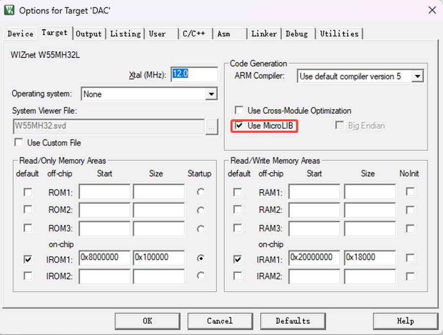
;First, determine whether the macro __MICROLIB has been defined. If this macro is defined, assign the global attributes of the labels __initial_sp (stack top address), __heap_base (heap starting address), and __heap_limit (heap ending address) to the program, which can be called by external files. Regarding this macro, we configure it in KEIL. Please refer to the figure "Using the Micro Library". Then, the initialization of the stack is completed by the C library function _main.
If the variable __MICROLIB is not defined, then the double-segment memory mode will be used, and the label __user_initial_stackheap will be declared with global attributes, allowing the user to initialize the stack themselves.
IF, ELSE, ENDIF: Assembly conditional branch statements, similar to the if, else in C language.
END: File end
WIZnet is a fabless semiconductor company founded in 1998. Its products include the Internet processor iMCU™, which utilizes TOE (TCP/IP Offload Engine) technology and is based on a unique patented fully hardwired TCP/IP. The iMCU™ is designed for embedded Internet devices in various applications.
WIZnet has more than 70 distributors globally and has offices in Hong Kong, South Korea, and the United States, providing technical support and product marketing services.
The regions managed by the Hong Kong office include Australia, India, Turkey, and Asia (excluding South Korea and Japan).