
Chapter 6: W55MH32 GPIO Input - Key Press Detection
Chapter 6: W55MH32 GPIO Input - Key Press Detection
Chapter 6: GPIO Input - Key Press Detection
Reference materials for this chapter: "W55MH32 Chinese Reference Manual". The key detection in this chapter utilizes the basic input function of the GPIO peripheral.
1 Hardware Design
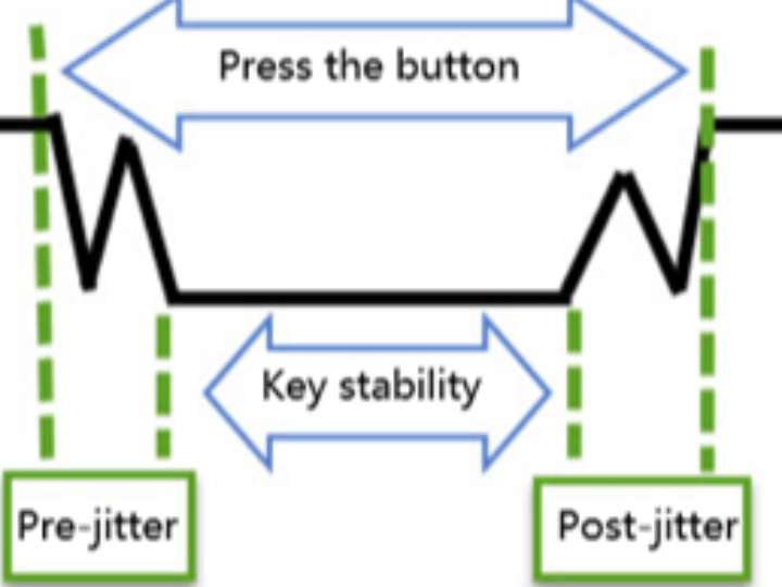
When the mechanical contacts of the button are disconnected or closed, due to the elastic effect of the contacts, the button switch will not immediately stabilize in either the connected or disconnected state. When using the button, there will be button jitter, indicating the presence of the ripple signal in the figure. This requires software anti-jitter processing and filtering, which is inconvenient for input detection. This experimental board is connected with hardware anti-jitter function. See the following figure:
It utilizes the delay of capacitor charging and discharging to eliminate the ripple, thereby simplifying the software processing. The software only needs to directly detect the level of the pin.
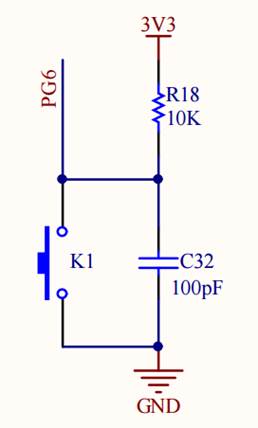
From the schematic diagram of the key, it can be seen that when these keys are not pressed, the input state of the GPIO pin is a low level (the circuit where the key is located is not connected, and the pin is grounded). When the key is pressed, the input state of the GPIO pin is a high level (the circuit where the key is located is connected, and the pin is connected to the power supply). As long as we detect the input level of the pin, we can determine whether the key has been pressed.
If the connection method or pin of the keys on the experimental board you are using is different, you only need to modify the pins according to our engineering, and the control principle of the program is the same.
2 Software Design
2.1 Key-press input detection method
The key input detection method is divided into two types: timed scanning and external interrupt. The working principle and advantages and disadvantages are as follows. In this article, we mainly explain the use of external interrupt for key input detection.
2.1.1 Key press scanning
Working principle: Through CPU timing or continuously reading the level status of the GPIO pin connected to the key, it determines whether the key has been pressed. For example, in a loop, repeatedly detect whether the corresponding pin is at a high or low level. If it was originally at a high level and is detected as a low level, and after debouncing processing (generally through delay, such as 5-10ms and rechecking again), it remains at a low level, then it is considered that the key has been pressed; when released, it is the opposite. Independent key scanning is to separately detect each key pin; matrix key scanning is to scan by rows or columns, and determine which key has been actuated through the intersection points of rows and columns.
Advantages:
● The principle is simple and easy to understand, and it is relatively easy to implement. It is also friendly for beginners.
● The scanning frequency and timing can be flexibly controlled. In some scenarios where the real-time requirements for key detection are not high and the system resources are abundant, it can work very well.
Disadvantages:
- It consumes CPU resources. The CPU needs to continuously execute scanning programs to detect the key status. If there are other tasks in the system, it will affect the overall operational efficiency.
- The real-time performance is poor because it is performed in a timed or continuous manner. It cannot respond promptly to key actions, resulting in detection delays.
2.1.2 External interrupt
Working principle: When an external event occurs, such as when a key is pressed causing the level on the external interrupt pin connected to the microcontroller to change (which can be configured as rising edge triggered, falling edge triggered, or both edge triggered), the interrupt system of the microcontroller will force the CPU to pause the currently executing program and switch to execute the pre-written interrupt service program to handle the event. After processing, it will return to the original interrupt location to continue executing the original program. Taking the key as an example, the key is connected to the external interrupt pin. When the key is pressed, the level changes, triggering the interrupt request. After the CPU responds, it enters the interrupt service function to handle the key event.
Advantages:
●High real-time performance, capable of responding promptly to external events as they occur, and quickly handling events. It is suitable for scenarios with high real-time requirements, such as the rapid response to sudden signals in industrial control.
●Saves CPU resources. The CPU does not need to continuously poll and detect the key status. It only processes related affairs when an external event triggers an interrupt, thereby improving the efficiency of CPU usage. Disadvantages:
● The configuration is relatively complex and requires correct settings for interrupt-related registers (such as interrupt enable register, interrupt priority register, interrupt trigger mode register, etc.). This imposes high requirements on developers.
● When multiple interrupt sources simultaneously request an interrupt, it is necessary to properly handle issues such as interrupt priority and interrupt nesting. Otherwise, it may lead to abnormal system operation.
2.2 Programming essentials
1. Enable the clock of the GPIO port;
2. Initialize the GPIO target pin to the input mode (floating input);
3. Write a simple test program to detect the state of the button.
2.3 Code analysis
1. Header file inclusion and macro definitionHeader files included: Include standard library header files stdlib.h, string.h, and stdio.h, as well as custom header files delay.h and w55mh32.h.
Macro definitions:
- GPIO_GROUP_TEST:The GPIO group used in the definition is designated as GPIOG.
- GPIO_MODE_TEST:Define the GPIO mode as the pull-up input mode: GPIO_Mode_IPU.
- GPIO_SPEED_TEST:Define the GPIO speed as 50 MHz.
- GPIO_PIN_TEST:The GPIO pin used is defined as GPIO_Pin_5.
- USART_TEST:Define the used USART peripheral as USART1.
2. Function declaration
void UART_Configuration(uint32_t bound);Two functions are declared: UART_Configuration is used for configuring serial communication, and GPIO_Configuration is used for configuring GPIO pins and external interrupts.
3. Main function
int main(void)Initialization operation:
- delay_init():Initialize the delay function.
- UART_Configuration(115200):Configure serial communication with a baud rate of 115200.
- RCC_GetClocksFreq(&clocks):Obtain the system clock frequency information.
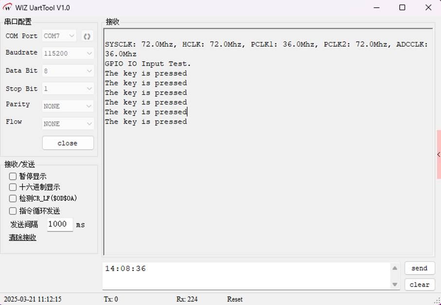
Print information: Print the system clock frequency information and test prompt information.
GPIO configuration: Call the GPIO_Configuration() function to configure the GPIO pins and external interrupts.
Main loop: Enter an infinite loop to wait for the external interrupt to trigger.
4. GPIO_Configuration function
void GPIO_Configuration(void)Clock Enable: Enable the clock for GPIOG and the re-mapped function I/O (AFIO).
GPIO Initialization: Configure GPIO_Pin_5 of GPIOG as an input with pull-up mode and a speed of 50MHz.
External Interrupt Line Configuration: Map GPIO_Pin_5 of GPIOG to the external interrupt line EXTI_Line5.
NVIC Configuration:
● Configure the interrupt channel EXTI9_5_IRQn for external interrupt lines 5 to 9.
● Set theTake the lead; seize the initiative priority to 2, the sub-priority to 3, and enable this interrupt channel.
EXTI Configuration: Configure the external interrupt line EXTI_Line5 as an interrupt mode, triggered by the falling edge, and enable this interrupt line.
5. EXTI9_5_IRQHandler function
void EXTI9_5_IRQHandler(void) Interrupt Handling:
● Check if the interrupt flag of the external interrupt line EXTI_Line5 is set.
● Perform 10ms of debouncing processing.
● Read the input level of GPIOG's GPIO_Pin_5. If it is a low level, print "The key is pressed".
● Clear the interrupt flag of the external interrupt line EXTI_Line5.
6. UART_Configuration function
void UART_Configuration(uint32_t bound)Clock Enable: Enable the clocks for USART1 and GPIOA.
GPIO Initialization:
● Configure GPIOA's GPIO_Pin_9 as a reprogrammable push-pull output mode, used as the transmission pin for USART1.
● Configure GPIOA's GPIO_Pin_10 as an open-drain input mode, used as the reception pin for USART1.
USART Initialization:
● Configure USART1's baud rate, data bits, stop bits, parity bit, hardware flow control, and operating mode.
● Enable USART1.
7. EXTI1_IRQHandler function
void EXTI1_IRQHandler(void)Interrupt handling: Handles the interrupt event of the external interrupt line EXTI_Line1, similar to EXTI9_5_IRQHandler, but this interrupt is not used in this code.
8. SER_PutChar function and fputc function
int SER_PutChar(int ch)SER_PutChar function: Sends a character through USART and waits for the completion flag to be set.
fputc function: Redirects the standard output function, replaces the newline character \n with the carriage return character \r before sending.
2.4 Download verification
Download the compiled program to the development board and reset it. Press the button to check on the serial port whether the button has been pressed.
WIZnet is a fabless semiconductor company founded in 1998. Its products include the Internet processor iMCU™, which utilizes TOE (TCP/IP Offload Engine) technology and is based on a unique patented fully hardwired TCP/IP. The iMCU™ is designed for embedded Internet devices in various applications.
WIZnet has more than 70 distributors globally and has offices in Hong Kong, South Korea, and the United States, providing technical support and product marketing services.
The regions managed by the Hong Kong office include Australia, India, Turkey, and Asia (excluding South Korea and Japan).