
Chapter 5: GPIO Output in W55MH32 - Using the Firmware Library to Light Up an LED
Chapter 5: GPIO Output in W55MH32 - Using the Firmware Library to Light Up an LED
Chapter 5: GPIO Output - Using the Firmware Library to Light Up an LED
References for this chapter: "W55MH32 - Reference Manual" - GPIO and RCC sections, library help documentation.
By using the pre-built engineering template from the library, it becomes very convenient to write applications using the standard library. It can be said that from this chapter, we truly begin to step into the realm of firmware library development. The control of the LED light utilizes the basic output function of the GPIO peripheral.
5.1 Hardware Design
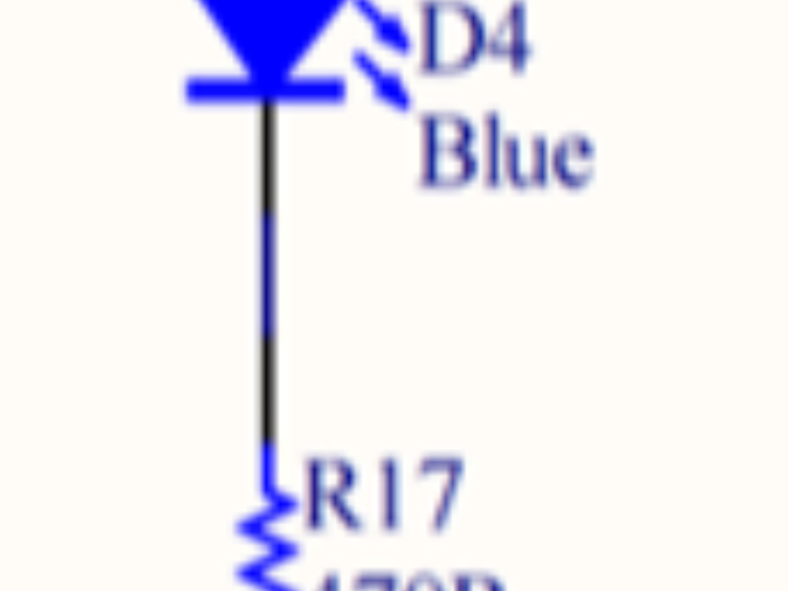
In this tutorial, the connection between the W55MH32 chip and the LED light is shown in the figure "LED Hardware Schematic Diagram".
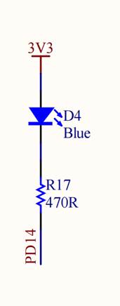
This circuit is a reference circuit. The cathode of this LED light is all connected to the GPIO pins of W55MH32. As long as we control the level output state of the GPIO pins, we can control the on/off of the LED light. If the connection method or pins of the LED light on the experimental board you are using are different, you only need to modify the pins according to our engineering, and the control principle of the program is the same.
5.2 Software Design
5.2.1 Programming essentials
1. Enable the clock of the GPIO port;
2. Initialize the GPIO target pin to the push-pull output mode;
3. Write a simple test program to control the GPIO pin to output high and low levels.
5.2.2 Code analysis
1. Header file and macro definition
#include <stdlib.h>
#include <string.h>
#include <stdio.h>
#include "delay.h"
#include "w55mh32.h"

#define GPIO_GROUP_TEST GPIOB
#define GPIO_MODE_TEST  GPIO_Mode_Out_PP
#define GPIO_SPEED_TEST GPIO_Speed_50MHz
#define GPIO_PIN1_TEST  GPIO_Pin_0
#define GPIO_PIN2_TEST  GPIO_Pin_2
#define GPIO_PIN3_TEST  GPIO_Pin_3

USART_TypeDef *USART_TEST = USART1;
Header file: Includes the standard library and custom header files (such as delay and chip-related libraries).
Macro definitions:
GPIO_GROUP_TEST: Specifies the use of GPIOB.
GPIO_MODE_TEST: Set to push-pull output (GPIO_Mode_Out_PP) for driving external devices (such as LEDs).
GPIO_PIN1_TEST/Pin2/Pin3: Defines three output pins (PB0, PB2, PB3).
Serial port configuration: Uses USART1 for communication.
2. Function Declaration
void UART_Configuration(uint32_t bound);
void GPIO_Configuration(void);
3. Main function (main logic)
int main(void)Initialization: Delay, serial port, clock frequency acquisition.
Serial port output: Print system clock information and test prompts.
GPIO configuration: Set the three pins of GPIOB as outputs.
Flow light logic:
GPIO_SetBits: Set high level (turn off LED).
GPIO_ResetBits: Set low level (turn on LED).
delay_ms(200): Each action interval is 200ms, forming a cyclic flashing.
4. GPIO_Configuration Function (GPIO Initialization)
void GPIO_Configuration(void)Clock Enable: Enable the clock for GPIOB.
Pin Configuration:
Pin: PB0, PB2, PB3 (configured simultaneously through bit OR operation).
Mode: Push-Pull Output (GPIO_Mode_Out_PP), suitable for driving peripherals such as LEDs.
Speed: 50 MHz (satisfies the requirement for high-frequency operation).
5. UART_Configuration Function (Serial Port Initialization)
void UART_Configuration(uint32_t bound)Pin configuration:
PA9 (TX): Reused as push-pull output (for data transmission).
PA10 (RX): Floating input (for data reception).
Serial port parameters: 115200 baud rate, 8 data bits, 1 stop bit, no parity check.
6. Serial port output function (SER_PutChar and fputc)
int SER_PutChar(int ch)SER_PutChar: Sends a single character via USART and waits for the transmission completion flag (USART_FLAG_TC).
fputc: Redirects the printf function of the C library to the serial port, supporting automatic addition of carriage return (\r) for newline characters (\n).
5.2.3 Download verification
Download the compiled program to the development board and reset it. You will see the interaction between the LED's on and off.
5.3 W55MH32 Standard Library Supplementary Knowledge
5.3.1 Where did the SystemInit function go?
This function is defined in the "system_w55mh32.c" file of the W55MH32 standard library, and our project already includes this file. The SystemInit function in the standard library sets the system clock of the chip to 72 MHz, which means the AHB clock frequency is 72 MHz, APB2 is 72 MHz, and APB1 is 36 MHz. When the W55MH32 chip powers on, after executing the instructions in the startup file, this function will be called to set the system clock to the above state.
5.3.2 Assertion
5.3.2.1 The function of assertion
During the development of W55MH32, the code written by the developers needs to perform checks on various parameters and states. Assertions provide a simple and effective way to insert checkpoints in the code to verify whether certain conditions are met. If the conditions are not met, the assertion will trigger an error, helping the developers quickly locate and solve the problem. Please refer to the code listing for details: GPIO output - 1 :
Code Listing: GPIO Output - -1 Section of the Assertion in GPIO_Init Function
void GPIO_Init(GPIO_TypeDef* GPIOx, GPIO_InitTypeDef* GPIO_InitStruct)Basically, at the beginning of each library function, there will be something like this. Here, "assert_param" is actually a macro. In the library function, it is used to check whether the input parameters meet the requirements. If the requirements are not met, it will execute a certain function to output a warning. The definition of "assert_param" can be found in the code list: GPIO output - 2 :
Code listing: GPIO output - 2 Definition of assertions in the w55mh32_conf.h file
#ifdef USE_FULL_ASSERT
#define assert_param(expr) ((expr) ? (void)0 : assert_failed((uint8_t *)__FILE__, __LINE__))The meaning of this code is as follows: If we do not define the "USE_FULL_ASSERT" macro, then "assert_param" is an empty macro (#else and #endif statements are effective), and it does not perform any operation. As a result, all the assert_param statements in the library functions are actually meaningless, and we can simply ignore them.
If we define the "USE_FULL_ASSERT" macro, then "assert_param" is a statement with operations (#if and #else statements are effective). This macro uses the question mark expression in C language to judge the parameter expr. If the value of expr is true, then there is no operation (void 0), if the value of the expression is false, then the "assert_failed" function is called, and the input parameters of this function are "__FILE__" and "__LINE__", which respectively represent the "filename" and "line number" when the "assert_param" macro is called.
However, the library file only writes the function declaration for "assert_failed", but does not write the function definition. In practice, users need to define it themselves. We usually use the printf function to output this information. See code listing: GPIO output - 3 :
Code snippet: GPIO output -3 assert_failed - Output error message
void assert_failed(uint8_t * file, uint32_t line)Then why is the value of the expr parameter in the assert_param macro false when the input parameters of the function are incorrect? This needs to go back to the GPIO_Init function and look at its call to the assert_param macro. When it is called, it takes parameters such as "IS_GPIO_ALL_PERIPH(GPIOx)" and "IS_GPIO_PIN(GPIO_InitStruct->GPIO_Pin)" as input parameters. That is to say, when it is called, expr is actually a judgment expression for the input parameters. For example, the macro definition of "IS_GPIO_PIN":
#define IS_GPIO_PIN(PIN) ((PIN) != (uint32_t)0x00)If the input parameter PIN value is 0, the value of the expression is false; when PIN is not 0, the value of the expression is true. We know that the value of the macro "GPIO_Pin_x" used to select the GPIO pin number has at least one bit set to 1. Only in this case is the input parameter meaningful. If the value of GPIO_InitStruct->GPIO_Pin is 0, the input parameter is invalid. Combined with the expression "IS_GPIO_PIN", "assert_param" implements the function of checking the input parameter. Other calling methods of the assert_param macro are similar. You can study them by yourself by looking at the source code of the library.
5.3.3 Doxygen Comment Specification
In the W55MH32 standard library and the files we have written ourselves, one can observe some rather distinctive comments, similar to the code snippet: GPIO output - 4:
Code listing: GPIO output - 4 Doxygen comment specification
/**
* @brief Initialize the IO for controlling the LEDThis is a kind of annotation specification called "Doxygen". If annotations are made in the engineering files according to this specification, the Doxygen software can automatically generate help documents based on the annotations. The very important library help documentation we are talking about.
5.3.4 Prevent the repetition of including header files
In all the header files of the W55MH32 standard library as well as the .h header files we have written ourselves, one can see a similar code snippet: the macro definition for GPIO output -5. Its function is to prevent the header files from being included multiple times, thus avoiding compilation errors.
Code listing: GPIO output - -5 - Macro to prevent duplicate inclusion of header files
#ifndef __LED_HAt the beginning of the header file, use the " #ifndef " keyword to check if the label "__LED_H" has been defined. If it has not been defined, then the content between the " #ifndef " and " #endif " keywords is valid. That is to say, if this header file is included by other files, it will be included in that file and the label "__LED_H" defined in the header file will be defined using the " #define " keyword immediately after. When this header file is included by the same file for the second time, due to the " #define __LED_H " definition in the first inclusion, when checking " #ifndef __LED_H ", the result of the check is false. The content between " #ifndef " and " #endif " is invalid, thus preventing the same header file from being included multiple times, and no "redefine" error will occur during compilation.
Generally speaking, we do not directly write two "#include" statements in the C source file to include the same header file, but due to the internal inclusion in the header file, there may be repetition. This code is mainly to avoid such problems.
WIZnet is a fabless semiconductor company founded in 1998. Its products include the Internet processor iMCU™, which utilizes TOE (TCP/IP Offload Engine) technology and is based on a unique patented fully hardwired TCP/IP. The iMCU™ is designed for embedded Internet devices in various applications.
WIZnet has more than 70 distributors globally and has offices in Hong Kong, South Korea, and the United States, providing technical support and product marketing services.
The regions managed by the Hong Kong office include Australia, India, Turkey, and Asia (excluding South Korea and Japan).