
Chapter 36: W55MH32’s CAN - Controller Area Network Interface
Chapter 36: W55MH32’s CAN - Controller Area Network Interface

Chapter 36: W55MH32’s CAN - Controller Area Network Interface
The Controller Area Network (CAN) is a core communication technology in the fields of industrial automation and automotive electronics, renowned for its high reliability and real-time performance. In the following section, based on the bxCAN (basic extended CAN) module of the W55MH32 Ethernet single-chip microcontroller, we will systematically explain the principles, architecture, and practical application points of CAN communication, and together with you, we will learn and utilize this technology.
Overview of CAN Communication
Introduction
Functional Features
The CAN interface has the following features:
- Multi-master communication mechanism: All nodes in the network can actively send data at any time without the need for a central controller to coordinate. When multiple nodes send data simultaneously, the priority is determined through identifier arbitration to ensure that high-priority messages are transmitted first.
- Non-destructive bus arbitration: The arbitration process is based on the binary value of the identifier, with smaller values indicating higher priority. Nodes that fail the arbitration will automatically stop sending to avoid bus conflicts.
- Error handling: Multiple error detection mechanisms such as CRC verification and response verification are integrated. When an error is detected, an error frame is automatically sent, and fault determination (active error, passive error, offline state) is achieved through the error counter.
- Real-time guarantee: The communication rate can reach up to 1 Mbps (short distance), meeting the requirements of real-time control scenarios.
CAN Frame Structure and Types
The CAN protocol defines four types of frames, each of which has a specific structure and function:
Frame type | Function | Structural Characteristics |
Data frame | Transmit data | It includes the frame start, arbitration segment, control segment, data segment, CRC segment, response segment and frame end. The data length ranges from 0 to 8 bytes. |
Remote frame | Request other nodes to send data | There is no data segment. The arbitration segment identifier is used to identify the requested message. After the receiving node receives the remote frame, it sends the corresponding data frame. |
Error frame | Send when an error is detected. | It is composed of error flags (6 consecutive explicit bits) and error delimiters (8 implicit bits), and is sent by all nodes when an error is detected. |
Overload frame | Notify other nodes that their own receiving buffers are full. | Used to delay data transmission, it consists of an overload flag and an overload delimiter. |
Identifiers and Priority
The CAN frame determines the priority through the identifier (ID). The smaller the ID, the higher the priority.
The W55MH32 supports two frame formats:
- Standard frame: 11-bit ID.
- Extended frame: 29-bit ID.
The identifier does not represent the node address, but is related to the message content. For instance, the message "engine speed" in an automobile might correspond to the identifier 0x100, and all nodes subscribing to this message can receive it.
Detailed Explanation of the bxCAN Module in W55MH32
Functional Features
The W55MH32 integrated bxCAN (Basic Extended CAN) module is a high-performance CAN controller, specifically designed to reduce the CPU load. Its key features include:
- Protocol compatibility: Fully supports CAN 2.0A and 2.0B active modes, with a maximum baud rate of 1 Mbps.
- Sending processing capability: 3 independent sending mailboxes, supporting priority configuration and timestamp recording (the timer value of the start time of the sending frame).
- Receiving management mechanism: 2 3-level deep receiving FIFOs (FIFO0 and FIFO1), hardware automatically manages message storage, reducing CPU intervention.
- Flexible filtering system: 14 configurable filter groups, supporting 32-bit or 16-bit filtering width, can be set to mask bit mode or identifier list mode.
- Time-triggered communication: Supports TTCM mode, the internal 16-bit timer adds a timestamp to the message, suitable for scenarios with extremely high real-time requirements.
Hardware Resources and Memory Mapping
The hardware resources of the bxCAN module include:
- Pin connection: Connect the external transceiver (such as TJA1050) through the CANX and CANRX pins. The bus needs to be connected to a 120Ω termination resistor.
- Register group: Includes control register (CAN_MCR), status register (CAN_MSR), sending status register (CAN_TSR), receiving FIFO register (CAN_RF0R/CAN_RF1R), etc. There are a total of 32 32-bit registers, with the address range from 0x00 to 0x31C.
- Shared memory: Shares 512 bytes of SRAM with the USB module for data transmission buffering. Both cannot be used simultaneously.
Clock and Baud Rate
The clock of bxCAN originates from the APB1 bus, and its baud rate calculation formula is:
Baud rate = System clock / [2 × CAN_BRP × (CAN_SJW + 1 + CAN_BS1 + 1 + CAN_BS2 + 1)]
- CAN_BRP: Baud Rate Divider, range 1 to 1024.
- CAN_SJW: Resynchronization Jump Width, determines the compensation capability for bus phase error.
- CAN_BS1/CAN_BS2: Time Period 1 and Time Period 2, used to define the sampling point position and bit timing.
For example, when the system clock is 72 MHz, setting CAN_BRP = 9, CAN_SJW = 1, CAN_BS1 = 6, and CAN_BS2 = 3, the baud rate is 1 Mbps, and the sampling point is located at the 75% time point, which takes into account both anti-interference ability and synchronization capability.
bxCAN Working Mode and State Transition
Working Mode
bxCAN supports three main working modes, which can be configured through the CAN_MCR register:
Initialization mode
- Entry condition: Set CAN_MCR.INRQ = 1, and wait for CAN_MSR.INAK = 1 to confirm.
- Function: Only in this mode can the baud rate (in the CAN_BTR register) and filter group parameters (bit width, mode, FIFO association, etc.) be configured.
- Notes: After initialization, this mode must be exited to enable normal communication. When exiting, wait for the bus to be idle (detect 11 consecutive silent bits).
Normal mode
- Working state: Supports complete sending and receiving functions. Once the node synchronizes with the bus, it can send and receive messages.
- Synchronization mechanism: Achieves bit synchronization by detecting the rising edge of the frame start bit (SOF), and then adjusts the phase error through re-synchronization.
- Typical applications: Data interaction in industrial control, real-time communication between automotive ECU's.
Sleep mode
- Low-power design: The clock stops, only the wake-up logic is retained, significantly reducing power consumption.
- Wake-up method: Clear the CAN_MCR.SLEEP bit through software, or detect bus activity through hardware (CAN_MCR.AWUM=1 needs to be set).
- Application scenarios: Energy-saving mode for battery-powered devices, such as the standby state of vehicle sensors.
Testing Mode: Silence and Loopback
To facilitate development and debugging, bxCAN supports two test modes. The CAN_BTR register needs to be configured in the initialization mode.
Silent Mode (SILM = 1)
- Features: It can receive data frames and remote frames, but during transmission, it only outputs the idle bits without affecting the bus state.
- Usage: It is used for analyzing bus activities without interfering with existing communications, such as bus monitoring during fault diagnosis.
Loopback mode (LBKM = 1)
Feature: The transmitted message is directly looped back internally to the receiving end and the CANRX pin input is ignored.
Usage: For self-test scenarios, the receiving and transmitting functions can be verified without external hardware, such as for self-testing before module production.
Loopback Silent Mode (SILM = 1 + LBKM = 1)
- Combination features: It has both loopback and mute functions. The transmission of messages does not affect the external bus, and it is only for internal loopback testing.
- Security test: Suitable for "hot self-test", avoiding interference with actual bus communication.
Message Sending and Receiving Processing Mechanism
Processing Flow for Sending
- The sending process of bxCAN is automatically managed by the hardware. The software only needs to configure the mailbox and request the transmission.
- Email selection: 3 sending email addresses (email 0 to 2), any email can be selected when idle.
- Parameter configuration: Set identifier (STDID/EXID), frame type (data frame/remote frame), data length (DLC) and data content.
- Send request: Set CAN_TIxR.TXRQ bit, the email status changes to "registered", waiting for arbitration.
- Arbitration and sending: After successful arbitration, it enters the "sending" state, and after sending is completed, CAN_TSR.TXOK bit is set to 1, and the email is reset to idle.
Priority rule for sending
- Identifier priority: When CAN_MCR.TXFP = 0, messages with smaller identifier values are sent first; when identifiers are the same, messages with smaller mailbox numbers are sent first.
- FIFO priority: When CAN_MCR.TXFP = 1, they are queued according to the order of the sending requests, which is suitable for segmented transmission scenarios.
Receiving Management and FIFO Mechanism
The reception and processing are achieved through two 3-level deep FIFOs, and are fully managed by hardware.
- Valid message determination: Messages that are correctly received (without CRC errors, format errors, etc.) and pass the filter check are considered valid messages.
- FIFO storage: Valid messages are stored in the FIFOs in the order of reception, with FIFO0 and FIFO1 being independent and can be associated with different FIFOs through filter configuration.
- Status indication: The FMP[1:0] bits in CAN_RF0R/FIFO1R indicate the number of messages in the FIFO (0 to 3), and the FULL bit is set to 1 when the FIFO is full.
- Overflow handling: The FIFO lock mode can be configured (CAN_MCR.RFLM = 1), in which case new messages will be discarded; otherwise, the latest message will overwrite the old one.
Timestamp and filter matching sequence number
- Timestamp: Each received message records the 16-bit timer value of the frame's starting time, stored in CAN_RDTxR.TIME[15:0], for analyzing message delay.
- Filter Match Sequence Number (FMI): Records the number of the matched filter group, stored in CAN_RDTxR.FMI[7:0], allowing the software to quickly distinguish message types based on this.
Identifier Filtering System Parsing
The Core Value of the Filtering Mechanism
In the CAN network, nodes usually only focus on certain messages. The function of the filter is to filter out valid messages at the hardware level, thereby reducing the CPU load. The filtering system of bxCAN has the following characteristics:
- 14 filter groups: Each group can be independently configured and supports standard frame and extended frame filtering.
- Variable bit width: Each group can be set to 32-bit single filter or 2 16-bit filters.
- Dual mode configuration: Shielded bit mode or identifier list mode, which can flexibly adapt to different scenarios.
Shielded Position Mode and List Mode
Masked Position Mode
- Working Principle: Each filter group contains 1 identifier register and 1 mask register. The positions with a mask value of 1 must be strictly matched, while the positions with a mask value of 0 are "unimportant".
- Typical Application: Filter a group of related messages, such as standard frames with identifiers ranging from 0x100 to 0x1FF. You can set the identifier to 0x100 and the mask to 0x0FF.
Identifier List Mode
- Working Principle: Both registers serve as identifier registers. Messages must exactly match one of them to pass through the filtering.
- Typical Application: Precisely filter specific messages. For example, only receive extended frames with an identifier of 0x200. Set both registers to the extended frame format of 0x200.
Filter Priority Rules
When a message matches multiple filters, the priority is determined by the following rules:
- Width priority: 32-bit filters have a higher priority than 16-bit filters.
- Pattern priority: List mode has a higher priority than masked bit mode.
- Number priority: Filters in a filter group with a smaller number have a higher priority (0-13).
For example, the filter group 0 of the 32-bit list mode has a higher priority than the filter group 1 of the 16-bit masked bit mode, ensuring that critical messages are processed first.
Error Management and Bus Health Monitoring
Error Detection and Counter Mechanism
bxCAN achieves fault identification by sending the error counter (TEC) and receiving the error counter (REC).
- Error types: support bit error, fill error, CRC error, format error, response error, etc. Error codes are stored in CAN_ESR.LEC[2:0].
- Counter update:
- When a transmission error occurs, TEC increases by 1; when a reception error occurs, REC increases by 1.
- When a successful transmission/reception is completed, TEC and REC decrease by 1 (if it exceeds 127, it is reduced to 120).
- When a transmission error occurs, TEC increases by 1; when a reception error occurs, REC increases by 1.
- State transition:
- When TEC or REC is greater than 127, enter the error passive state. At this time, the transmission error frame is a silent bit.
- When TEC is greater than 255, enter the offline state. Messages cannot be received or sent. It is necessary to re-join the network through automatic recovery or software intervention.
- When TEC or REC is greater than 127, enter the error passive state. At this time, the transmission error frame is a silent bit.
Offline Recovery Mechanism
The recovery method for the offline state is determined by the CAN_MCR.ABOM bit:
- Automatic recovery (ABOM = 1): Automatically returns to the error-active state after detecting 128 consecutive 11-bit silent bits.
- Manual recovery (ABOM = 0): The software needs to first request to enter the initialization mode, then exit, wait for bus synchronization, and then recover.
Error Interruptions and Status Monitoring
The CAN_IER register can be used to configure various error interrupts:
- Error Warning Interrupt (EWGIE = 1): Triggered when TEC or REC ≥ 96, indicating that the bus may have an abnormality.
- Passive Error Interrupt (EPVIE = 1): Triggered when entering the error passive state, requiring attention to the bus stability.
- Offline Interrupt (BOFIE = 1): Triggered when entering the offline state, requiring the startup of the recovery process.
- Last Error Code Interrupt (LECIE = 1): Updates the error code each time an error occurs and triggers the interrupt, facilitating quick problem location.
Application Scenarios
Industrial Automation Network
- Multi-device collaborative control: Real-time data exchange between PLC and sensors and actuators is achieved through the CANopen protocol, enabling device networking.
- Anti-interference design: Isolated transceivers (such as CTM1051) and shielded twisted-pair cables are used, and 120Ω termination resistors are connected at both ends of the bus to reduce the impact of electromagnetic interference.
- Automotive Electronic Systems
- Automotive Electronic Systems
- Vehicle network: Connects engine control unit (ECU), ABS, dashboard, etc., following J1939 or CANopen protocols.
- Low power consumption requirements: Utilizes sleep mode and wake-up function to reduce standby power consumption, meeting the power management requirements of automobiles.
Notes for Attention
Hardware Connection and Terminal Configuration
- Both ends of the bus must be connected to 120Ω termination resistors. No additional resistors are required at the intermediate nodes to avoid signal reflection caused by impedance mismatch.
- For industrial scenarios, it is recommended to use isolated transceivers (such as CTM1051) and shielded twisted-pair cables. The shield layer should be grounded at a single point to reduce electromagnetic interference.
Bit Rate Consistency Configuration
- The baud rate parameters (CAN_BRP, BS1, BS2, SJW) for all nodes must be exactly the same. It is recommended to hard-code these values in the registers to avoid calculation errors.
- For long-distance communication (>100m), the baud rate should be reduced to below 50 kbps, and the sampling point should be moved to the 80% position of the time (increase the BS1 parameter).
Filters and FIFO Management
- The unused filter groups should be set to the inactive state (the CAN_FA1R corresponding bit should be cleared to 0) to avoid invalid messages occupying resources.
- The receive FIFO needs to be queried regularly or enable interrupts (such as FMPIE) to prevent message overflow due to software processing delays.
Error Handling and Recovery Mechanism
- Monitor the transmission/reception error counter (TEC/REC). An alert is triggered when it exceeds 96, and it switches to the degraded mode when it exceeds 127.
- During offline recovery, if the manual mode is used (ABOM = 0), it is necessary to ensure that the initialization mode is exited and wait for the bus synchronization to complete (CAN_MSR.INAK = 0).
Low Power Mode Operation Specifications
- Before entering the sleep mode, it is necessary to confirm that all sending email boxes are empty (CAN_TSR.TME = 1). When waking up, the hardware bus activity detection (AWUM = 1) will be used first to reduce power consumption.
Program Design
CAN_LoopBack Routine
The CAN_LoopBack routine implements the CAN bus loopback test program. It receives instructions via the serial port to control the CAN data transmission, and automatically receives the loopback data for printing output. This is used to verify the functionality of the CAN controller. The following is the implementation process and result verification:
CAN Initialization
The CAN_Mode_Init() function is the CAN bus initialization function for W55MH32. Its content is as follows:
uint8_t CAN_Mode_Init(uint8_t tsjw, uint8_t tbs2, uint8_t tbs1, uint16_t brp, uint8_t mode)
This function configures the GPIOB pins (PB8 for receiving pull-up, PB9 for sending re-multiplexing) and the CAN1 controller, sets the working mode (including loopback test), bit timing parameters (sync segment, bit segment 1/2, division factor) to determine the baud rate, uses the 32-bit ID filter to receive all messages, and can selectively enable FIFO0 interrupt (requires defining CAN_RX0_INT_ENABLE), ultimately completing the initialization configuration of the CAN bus and preparing for communication.
CAN Data Transmission
Can_Send_Msg() is the function for sending CAN bus data:
uint8_t Can_Send_Msg(uint8_t *msg, uint8_t len)
This program first configures the CAN frame parameters (standard ID is 0x12, standard data frame, data length is specified by parameters), fills the data to be sent into the sending buffer, then calls the sending function and confirms the sending result through the mailbox status polling mechanism (waiting at most 0XFFF times), and finally returns success (0) or failure (1).
CAN Data Reception
Can_Receive_Msg() is the function for receiving CAN bus data:
uint8_t Can_Receive_Msg(u8 *buf)
By checking the status of the FIFO0 receiving buffer of CAN1, if there is data, the CAN frame information (including ID, data, etc.) is read. The valid data (up to 8 bytes) is copied to the user buffer and the actual data length (DLC) is returned. If there is no data, 0 is directly returned. This achieves a simple non-blocking CAN data reception function.
Serial Port Reception
GetCmd() is the single-character receiving function for the USART1 serial port:
uint8_t GetCmd(void)
By checking the non-empty flag of the receive buffer (RXNE), it determines whether there is data available for reading. If there is, it reads and returns the received characters (8 bits); otherwise, it returns 0.
Main Program
The main() function is the main program for the CAN bus loopback test:
int main(void)
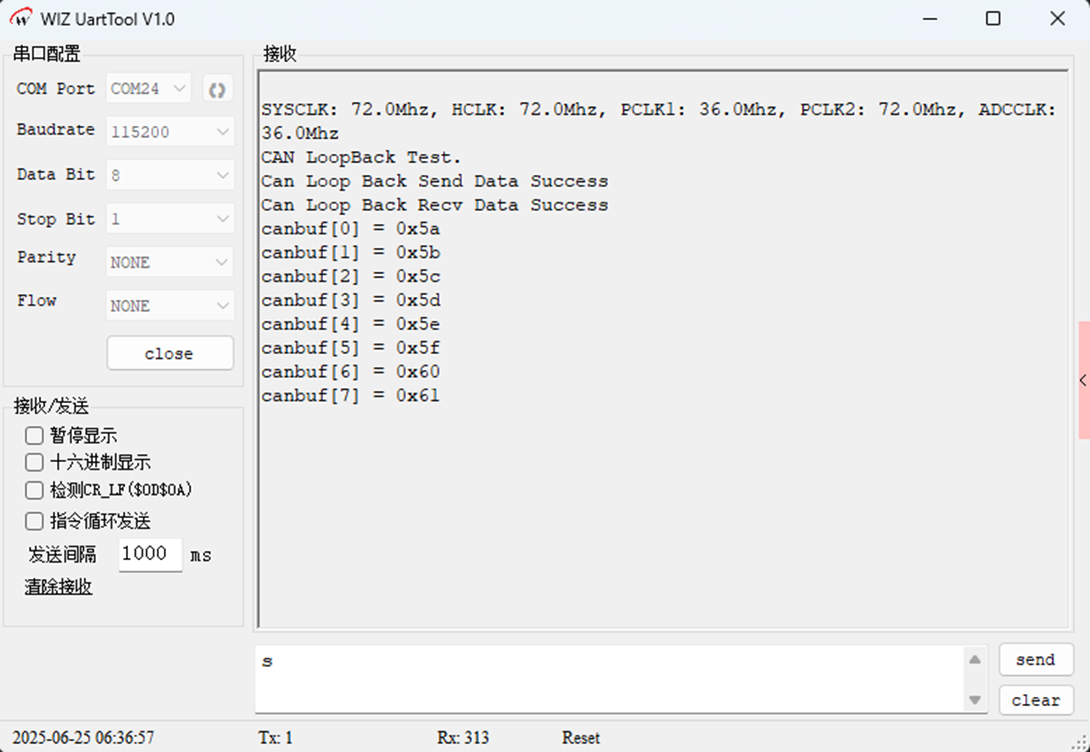
By initializing the system clock, UART1 and CAN controller (configured in loopback mode with a baud rate of 500 Kbps), the main loop listens to the serial port input. When the character "s" is received, 8-byte test data (0x5A to 0x61) is sent, and the CAN receive buffer is continuously checked. If data is received, the content is printed to achieve self-receiving and self-transmitting communication verification.
Download Verification
After the program is downloaded and run, it first prints out the frequencies of each system clock and the example name. After we manually send "s" through the serial port, the W55MH32 will send and receive data through the CAN interface to achieve the loopback test. After the sending and receiving are successful, corresponding prompt messages will be printed out. After the receiving is successful, the content of the receiving buffer will also be printed out at the same time.
CAN_Normal Routine
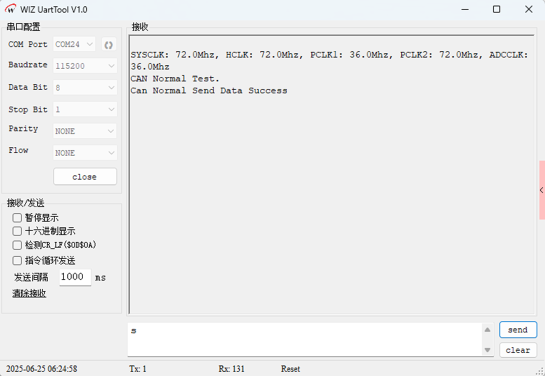
CAN_Normal is a communication test program for the normal mode of the CAN bus. Unlike the loopback test, it needs to communicate with external CAN nodes through the physical bus. This routine, apart from the CAN mode parameters set to CAN_Mode_Normal during CAN initialization, maintains consistency with the CAN_LoopBack routine in terms of the content of the CAN initialization function, the sending and receiving functions, and the main program. The changes are as follows:
CAN_Mode_Init(CAN_SJW_1tq, CAN_BS2_8tq, CAN_BS1_9tq, 4, CAN_Mode_Normal); //baud rate 500Kbps
Download Verification
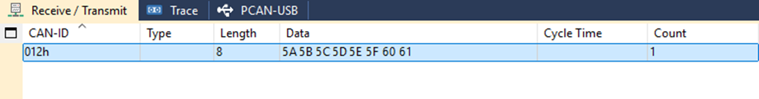
After the program is downloaded and run, it first prints out the frequencies of each system clock and the example name. After sending "s" via the serial port, the W55MH32 will send data through the CAN interface. Once the sending is successful, the serial port will print the message "Can Normal Send Data Success".
Summary
This article focuses on the bxCAN module of W55MH32 and elaborates on the core content of CAN communication. Firstly, it introduces the characteristics and frame structure of the CAN protocol, then analyzes the sending mailbox, receiving FIFO and working mode of bxCAN. Subsequently, it explains the transmission and reception mechanism, filtering rules, error management and baud rate configuration. Finally, it provides example programs and explanations from aspects such as hardware connection, parameter matching, and filtering configuration, to help everyone understand the use of CAN.
WIZnet is a non-chipfoundry semiconductor company founded in 1998. Its products include the Internet processor iMCU™, which adopts TOE (TCP/IP offloading engine) technology and is based on a unique patented fully hardwired TCP/IP. iMCU™ is designed for embedded Internet devices in various applications.
WIZnet has over 70 distributors worldwide, with offices in Hong Kong, South Korea, and the United States, providing technical support and product marketing.
The region managed by the Hong Kong office includes: Australia, India, Turkey, and Asia (excluding South Korea and Japan).