
Chapter 35: W55MH32’s I2S——Audio transmission interface
Chapter 35: W55MH32’s I2S——Audio transmission interface
Chapter 35: W55MH32’s I2S——Audio transmission interface
I2S (Inter-Integrated Circuit Sound) is an important interface used for digital audio transmission in the W55MH32 chip. It is widely applied in various audio devices and embedded systems. This article will explain the I2S interface from its working principle, precautions, application scenarios, and program design, and help you learn and use this technology together.
I2S Overview
Introduction
I2S (Inter-Integrated Circuit Sound) is a bus standard developed by Philips for the audio data transmission between digital audio devices, specifically designed for high-quality digital audio transmission between audio devices. In W55MH32, the I2S function shares the same hardware resources with the SPI module. By setting the I2SMOD bit of the register SPI_I2SCFGR to '1', the I2S function can be enabled, and the SPI module can be converted into an I2S audio interface.
The I2S interface and the SPI interface use approximately the same pins, flags, and interrupts, but are specifically optimized for audio data transmission. It uses separate wires to transmit the clock and data signals, by separating the data and clock signals, it avoids distortion caused by time differences, saving users the cost of purchasing professional equipment that resists audio jitter. I2S has become the de facto standard interface in the digital audio field and is widely used in various consumer electronics and professional audio devices.
Functional Features
The I2S interface of W55MH32 has the following features:
- Simple communication (only sending or receiving)
- Master or slave operation
- 8-bit linear programmable pre-divider, achieving precise audio sampling frequency (8KHz to 96kHz)
- Data format can be 16-bit, 24-bit or 32-bit
- Audio channel fixed data packet frame is 16 bits (16-bit data frame) or 32 bits (16, 24 or 32-bit data frames)
- Programmable clock polarity (stable state)
- Underflow flag in slave sending mode and overflow flag in master/slave receiving mode
- 16-bit data register used for sending and receiving, with one register at each end of the channel
- Supported I2S protocols:
- I2S Philips standard
- MSB aligned standard (left aligned)
- LSB aligned standard (right aligned)
- PCM standard (16-bit channel frame with long or short frame synchronization or 16-bit data frame expanded to 32-bit channel frame)
- Data direction is always MSB first
- Both sending and receiving have DMA capability
- The master clock can be output to the external audio device, with a ratio fixed at 256xFs (Fs is the audio sampling frequency)
Working Principle
The core working principle of the I2S interface is based on the coordinated operation of three main signal lines:
- Serial Clock (SCK/CK): Also known as Bit Clock (BCLK), it is generated by the master device and is used to synchronize data transmission. Each clock cycle corresponds to one bit of audio data. The formula for calculating the frequency of SCK is: SCK frequency = 2 × Sampling Frequency × Sampling Bit Number. For example, for a stereo audio with a 44.1kHz sampling rate and 16-bit precision, the SCK frequency should be 44.1kHz × 16 bits × 2 (left and right channels) = 1.4112MHz.
- Word Select (WS): Also known as Frame Clock (LRCK), it is used to indicate the channel to which the current audio data belongs. In the I2S Philips standard, WS '0' indicates left-channel data and '1' indicates right-channel data. The WS signal becomes effective 1 clock cycle before sending the first data bit (MSB).
- Serial Data (SD): Carries the actual audio data and is represented using binary complement code. The data is always transmitted from the highest bit (MSB), similar to the MSB priority mode of the SPI interface.
- In some systems that require higher precision clock synchronization, a fourth signal line can also be used:
- Master Clock (MCK): Provides a system clock reference for the external audio codec, usually set to 256 times the sampling frequency (256xFs). When the MCKOE bit in the register SPI_I2SPR is '1', W55MH32 can output this additional clock signal.
The data transmission in I2S follows strict timing relationships. According to the Philips standard for I2S, the sender changes the data at the falling edge of the clock signal (CK), and the receiver reads the data at the rising edge. The WS signal also changes at the falling edge of the clock signal. This synchronization mechanism ensures the reliability of data transmission, maintaining a low bit error rate even at high rates.
For the processing of different data formats, the I2S hardware provides automatic data alignment and padding functions. For instance, when 16-bit data is expanded to a 32-bit frame, the upper 16 bits (MSB) are the valid data, and the lower 16 bits are forcibly set to 0x0000 by the hardware, without the need for software intervention. When 24-bit data is expanded to a 32-bit frame, the upper 24 bits are the valid data, and the lower 8 bits are set to 0 by the hardware. This automatic processing greatly simplifies software development, especially when using DMA transmission.
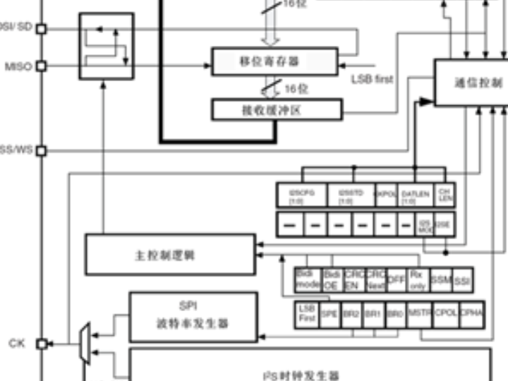
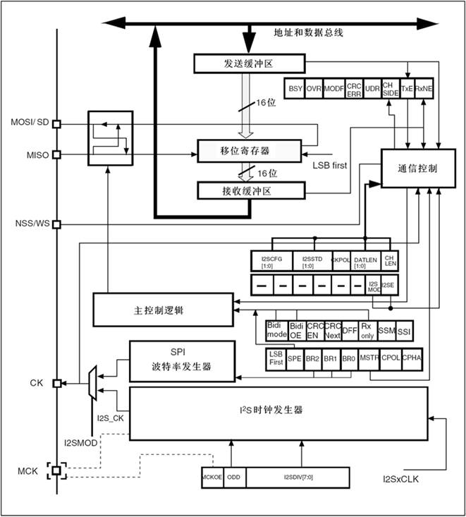
The functional block diagram of I2S is as follows:
I2S Utilizes DMA Communication
Working Principle of I2S in Combination with DMA Communication
When the I2S interface works in conjunction with the DMA controller, it forms an efficient data transmission channel. By setting the TXDMAEN/RXDMAEN bits in the register SPI_CR2 to 1, the DMA transmission request can be enabled. In I2S mode, the operation mode of the DMA is basically the same as that in SPI mode, except that there is no CRC function. When the I2S interface needs to send or receive data, a DMA request will be automatically triggered:
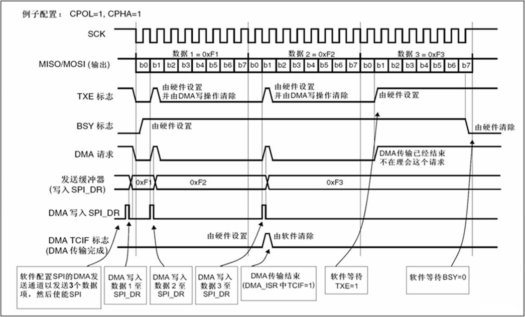
- Transmit process: When the TXE flag is set to 1, a DMA request is triggered. The DMA controller then transfers the data from the memory to the SPI_DR register.
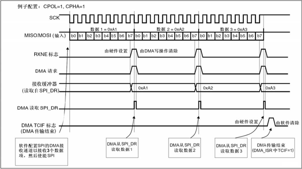
- Receive process: When the RXNE flag is set to 1, a DMA request is triggered. The DMA controller then transfers the data from the SPI_DR register to the internal memory.
The timing diagram for sending and receiving using DMA is as follows:
Configuration Key Points
Data format processing
The I2S supports multiple data formats, and the DMA requires corresponding configuration:
Data format | Number of DMA transmissions | Note |
16-bit → 16-bit frame | 1times | Direct transmission |
16-bit → 32-bit frame | 1times | Hardware automatically fills in zeros |
24-bit → 32-bit frame | 2times | Hardware adds 8 low-order 0s |
32-bit → 32-bit frame | 2times | Complete 32-bit processing |
Channel management
- The left-channel data is always transmitted first.
- The current channel is identified by the CHSIDE flag.
- The first data for the mode needs to be prepared in advance.
Sending process
- Configure DMA: Connect memory → SPI_DR, set data width
- Start transmission: Automatically triggered when TXE = 1
- Channel switching: Process left and right channels according to CHSIDE
- Completion processing: Close after waiting for TXE = 1 and BSY = 0
Receiving process
- Configure DMA: SPI_DR → memory, set data width
- Start transmission: Automatically triggered when RXNE = 1
- Data parsing: Process data alignment according to the standard
- Disable timing: Select the correct timing according to the data format
Application scenario
The I2S interface of W55MH32, with its high-quality digital audio transmission capability, has been widely applied in various fields:
Consumer Audio Devices
Portable music player: Connects to an audio DAC to achieve high-quality music playback, supporting digital audio transmission from an MP3 decoder to a power amplifier.
Smart speaker: Used for connecting the main control chip with the digital audio processor to realize the functions of voice assistant and music playback.
Digital TV and set-top box: Transmits digital audio signals to the audio processing chip or directly drives the digital power amplifier.
Professional Audio Equipment
Recording equipment: Connects to high-performance ADC to achieve multi-channel audio acquisition, supports 24-bit high-resolution recording.
Audio mixer: Mixes multiple audio sources in the digital domain while maintaining signal integrity.
Effect processor: Transmits audio data to the DSP chip for real-time effect processing.
Communication Equipment
VoIP phone: Enables two-way voice communication and supports advanced functions such as echo cancellation.
Conference system: Connects digital microphone arrays and audio processing units.
Wireless headphones: Transmits audio data between the Bluetooth module and the codec.
Automotive Electronics
Vehicle-mounted entertainment system: Connects multiple audio sources and amplifiers, supports surround sound processing.
Active noise cancellation system: Real-time acquisition of in-car noise and generation of inverse sound waves
Voice recognition system: Transmits high-definition voice data to the voice processing unit.
Embedded Systems
Industrial control human-machine interface: Achieves voice prompts and alarm functions.
Medical monitoring equipment: Transmits biological audio signals such as heart sounds and breathing sounds.
Smart home: Used for doorbells, intercom systems, and other devices that require audio functions.
Notes
- Clock Synchronization: Ensure initialization is completed before the external clock becomes valid.
- Data Alignment: Be aware of the differences in data alignment among various standards (Philips/MSB/LSB).
- Power Management: The power supply for the analog part needs to undergo enhanced filtering treatment.
- PCB Layout: The clock signal lines should be as short as possible and consider matching at the ends.
- Shutdown Sequence: Shut down the interfaces strictly in accordance with the specified procedures to avoid data corruption.
Program Design
IIS_CS4344 Routine
The IIS_CS4344 routine mainly realizes the I2S audio transmission function based on the W55MH32 chip. The implementation process and result verification are as follows:
I2S Initialization
The initialization function of I2S is the IIS_Configuration() function:
void IIS_Configuration(void)
This function first enables the relevant clock and releases the GPIOA15 resource (PA15 is default for the debugging interface. The default debugging function must be released first; otherwise, the debugging interface will continuously occupy this pin, causing the I2S to fail to work properly). Then, it configures GPIOA15, GPIOB3, GPIOB5 and GPIOC7 as multiplexed push-pull output mode to connect the SCK, SD, WS and MCLK signals of the I2S. Next, it initializes SPI3 as I2S mode and sets it to the host sending mode. It adopts the Philips standard, 16-bit data format, 8kHz sampling rate, enables MCLK output and low clock polarity. Finally, it enables DMA transmission to improve data efficiency and activates the I2S peripheral.
DMA Initialization
DMA_Configuration() is the initialization function for DMA:
void DMA_Configuration(void)
This function first enables the DMA2 clock, then initializes DMA2 channel 2 to operate in the mode of transferring data from memory to the peripheral, sets the peripheral base address to the data register of SPI3 (used for I2S communication), the memory base address to I2S3_Buffer_Tx (the audio data buffer), configures the transfer direction as from memory to peripheral, the buffer size as BufferSize, disables the peripheral address increment, enables the memory address increment, sets the data width to half-word (16 bits, matching the I2S data format), adopts the circular mode to ensure continuous transmission, sets the priority to very high, disables the memory-to-memory mode, and finally enables the transmission completion interrupt and temporarily disables the DMA channel.
Interrupt Configuration Function
The function NVIC_Configuration() is the configuration function for the NVIC (Nested Vector Interrupt Controller):
void NVIC_Configuration(void)
This function first defines the NVIC initialization structure, then sets the interrupt channel to DMA2 channel 2 (corresponding to the TX DMA transmission of I2S3), configures the抢占 priority and sub-priority both to 0 (the highest priority), enables the interrupt channel, and finally calls the initialization function to complete the configuration. Overall, it realizes the setting of a high-priority interrupt response for the DMA2 channel 2 transmission completion event, ensuring that audio data transmission interruptions can be handled promptly.
Interrupt Service Function
DMA2_Channel2_IRQHandler() is the interrupt service function for DMA2 channel 2:
void DMA2_Channel2_IRQHandler(void)The program first checks if it is the DMA transfer completion interrupt (TC2). If so, it clears the interrupt suspension bit and the completion flag bit, disables DMA2 channel 2 to suspend the transmission, and finally sets the flag bit Flag to 1 to notify the main program that the data transmission is complete. This overall realizes the response processing for the DMA transmission completion of I2S audio data, ensuring that necessary status updates and subsequent operations can be performed after the data transmission is completed.
Data Processing Function
The function DATA_Processing() is a data processing function, which achieves the conversion of 8-bit data to 16-bit format through the following steps:
void DATA_Processing(void)
The program first defines a loop counter, and then traverses the 8-bit data source array DATA of length DATA_LEN. Each time, it takes two consecutive 8-bit data, shifts the previous one 8 bits to the left, and performs a bitwise OR operation with the next one. The result is combined into a 16-bit data and stored in the target array I2S3_Buffer_Tx. This process fully realizes the conversion of 8-bit original data into a 16-bit data format suitable for I2S transmission, ensuring that the audio data can be correctly sent through the I2S interface.
Main Program
The main program (main()) achieves the continuous transmission of I2S audio data through the following steps:
int main(void)
The program first initializes the system clock and delay function, configures the UART with a baud rate of 115200 for debugging information output, obtains and prints the frequencies of all system clocks; then it configures the I2S interface, DMA channels, and NVIC interrupt controller, and converts the 8-bit raw data into a 16-bit format to adapt to I2S transmission; subsequently, it enables the DMA channel to start data transmission; finally, in the main loop, it detects the transmission completion flag Flag. If it is set to 1, it prints the success message, resets the flag, reconfigures and enables the DMA channel to achieve cyclic transmission, thereby fully realizing the function of continuously sending audio data through the I2S interface.
Download Verification
After the program is downloaded and run, it first prints the frequencies of all system clocks and the names of the examples. Then, for each successful transmission of I2S data, it prints the message indicating the successful data transmission.
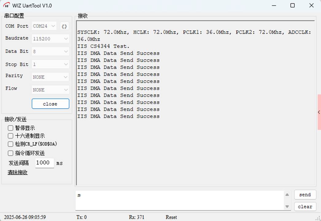
At this point, by connecting the DAC audio converter and putting on the headphones, you can continuously hear the audio message "WeChat transfer of 1 million yuan has arrived".
IS_Dma Routine
The IIS_Dma routine transmits the preset audio data through the I2S interface and the DMA transmission mechanism. The I2S initialization, DMA initialization, and interrupt configuration functions of this routine are consistent with those of the IIS_CS4344 routine, and their details will not be elaborated here. The other program design is as follows:
Transmitting Data
I2S3_Buffer_Tx represents the test data to be sent:
uint16_t I2S3_Buffer_Tx[BufferSize] = {0x0102, 0x0304, 0x0506, 0x0708, 0x090A, 0x0B0C,
Interrupt Service Function
DMA2_Channel2_IRQHandler is the interrupt handling function for DMA2 channel 2 in the W55MH32:
void DMA2_Channel2_IRQHandler(void)
The function is triggered when the DMA completes the preset 32 16-bit data transmissions. Firstly, it checks the transmission completion interrupt status. If the interrupt has been triggered, it clears the interrupt suspension bit and the transmission completion flag to avoid duplicate responses. Then, it disables DMA2 channel 2 to stop the data transmission. Finally, it sets the global flag bit Flag to 1 to notify the main program that the DMA transmission has been completed. The main loop will detect this flag and output a success message and reset the flag. This function realizes the interrupt response and status feedback of DMA transmission and is a key step in the I2S audio data transmission process.
Main Program
The main program (main()) achieves the transmission of I2S audio data through the following steps:
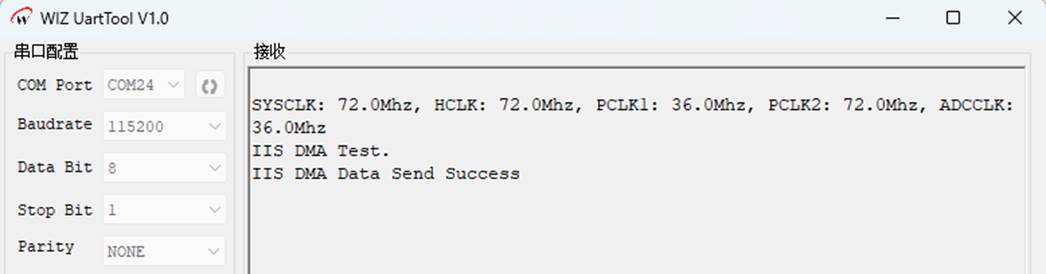
int main(void)The program first initializes the system clock, UART debugging interface and prints the clock information. Then, it configures the I2S interface (reusing SPI3), DMA2 channel 2 (in circular mode) and NVIC interrupt controller. Subsequently, it enables DMA and starts to cyclically transfer the preset 32 16-bit audio data to the I2S interface. The main loop continuously detects the completion flag Flag of DMA transmission. When the Flag is set to 1 by the interrupt handling function, it prints the transmission success message and resets the flag. However, since the interrupt handling function disables the DMA channel, the actual data can only be transmitted once. This code is often used for audio device initialization testing.
Download Verification
After the program is downloaded and run, it first prints the frequencies of each system clock and the example name. Then, when the I2S data transmission is successful, it prints the message indicating the successful data transmission.
The data sent can be decoded through a logic analyzer.
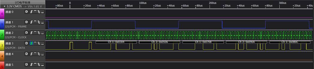
The data of the first frame and the last frame actually already show data pulse signals. This is due to the hardware initialization feature (FIFO filling) or the parser synchronization delay, and does not affect the actual audio functionality.
IIS_Int
The IIS_Int routine achieves interrupt-driven transmission of audio data through the I2S interface and the interrupt controller. The other programs are designed as follows:
I2S initialization
The IIS_Configuration() function is used to initialize the I2S interface of W55MH32 (reusing the SPI3 peripheral) and the interrupt configuration. Its content is as follows:
void IIS_Configuration(void)
The function first enables the clocks for GPIOA/B/C and SPI3, and configures the relevant pins as multiplexed push-pull outputs (including data output, byte selection, serial clock and master clock pins); then it configures the NVIC interrupt controller, sets the priority of the SPI3 interrupt and enables the interrupt; then it resets SPI3 and sets the I2S parameters, including master transmission mode, Philips standard, 16-bit data format, 8kHz sampling rate, low clock polarity and master clock output; finally, it enables the transmit buffer interrupt (TXE) and enables the I2S peripheral. This configuration is suitable for simple audio transmission scenarios and realizes data transmission through interrupt-driven mode.
Interrupt Service Function
SPI3_IRQHandler() is the interrupt handling function for the SPI3 peripheral, used to handle the I2S transmission buffer empty (TXE) event. The function content is as follows:
void SPI3_IRQHandler(void)
When the TXE flag is detected to be set, the function reads a 16-bit data from the preset 32-element data buffer I2S3_Buffer_Tx and sends it to the I2S interface, and increments the index TxIdx. When TxIdx reaches 32, it indicates that all data has been sent, and the function disables the TXE interrupt to stop the transmission. This function implements single data block transmission based on interrupts and is suitable for transmission scenarios involving small-scale and fixed data.
Main Program
The following is the main program of this routine, which is used to test the interrupt-driven data transmission function of the I2S interface:
int main(void)
The program first initializes the delay function and UART1 serial port, obtains and prints the frequencies of all system clocks, then initializes the I2S interface (configuring GPIO, interrupts and I2S parameters), and finally enters an infinite loop. The data transmission is driven by the interrupt of the I2S transmission buffer, and the main program does not participate in the specific transmission logic.
Download Verification
After the program is downloaded and run, it first prints out the frequencies of each system clock and the example name. After the I2S trigger interrupt occurs, data transmission begins. Once the data buffer has data, no more interrupts will be triggered.
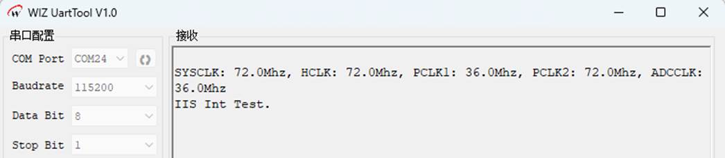
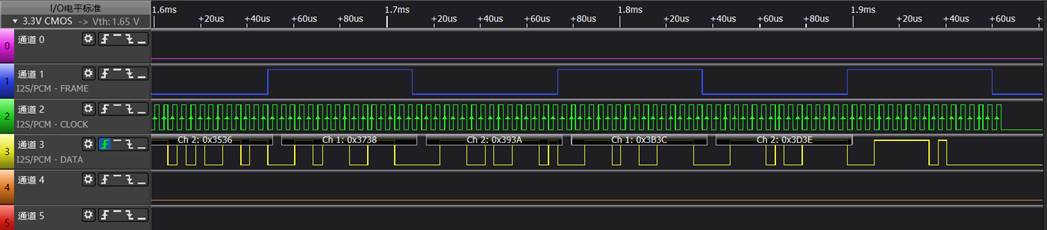
The logic analyzer parses the data as follows:
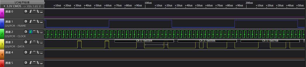
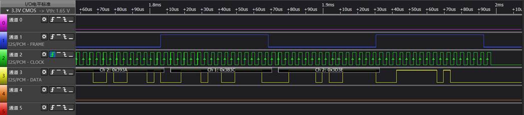
Similarly, the data of the first frame and the last frame can actually already be observed to have data pulse signals.
Summary
The I2S interface of W55MH32 offers a powerful and flexible solution for digital audio applications. By sharing hardware resources with the SPI module, it achieves the high performance of a dedicated audio interface while maintaining the cost-effectiveness of the design. Supporting multiple audio standards and data formats enables it to seamlessly collaborate with the vast majority of audio codecs, meeting various needs ranging from consumer electronics to professional audio equipment.
WIZnet is an off-chip semiconductor company founded in 1998. Its products include the Internet processor iMCU™, which employs TOE (TCP/IP offloading engine) technology and is based on a unique patented fully hardwired TCP/IP. iMCU™ is designed for embedded Internet devices in various applications.
WIZnet has over 70 distributors worldwide, with offices in Hong Kong, South Korea, and the United States, providing technical support and product marketing.
The region managed by the Hong Kong office includes: Australia, India, Turkey, and Asia (excluding South Korea and Japan).