
Chapter 31: W55MH32’s MCO—PA8 outputs from the main frequency.
Chapter 31: W55MH32’s MCO—PA8 outputs the frequency division result from the main frequency.
Chapter 31:
W55MH32’s MCO—PA8 outputs the frequency division result from the main frequency.
The MCO (Microcontroller Clock Output) of W55MH32 is an important clock output function, which enables the internal clock signal to be output through specific pins to the outside, for use by other devices or systems for synchronization. The following is a detailed explanation of the MCO function overview, application scenarios, and configuration steps:
Overview of MCO Function
Introduction
The MCO (Microcontroller Clock Output) of W55MH32 is a clock output pin of the microcontroller, which allows the internal clock source (such as HSI, HSE, PLL or system clock) to be output to the outside. It is mainly used for system debugging, external device synchronization or clock measurement.
Basic Concepts
MCO pin: Usually a specific GPIO (such as PA8 of the W55MH32 series), it needs to be configured in the re-mapped function (AF) mode.
Clock source: The clock source of MCO can come from various clock signals inside the W55MH32, such as:
- HSI (internal high-speed clock): Default 8MHz (may vary for different models).
- HSE (external high-speed clock): External crystal or clock source (such as 8MHz).
- PLL output: The system clock (SYSCLK) after frequency multiplication by the phase-locked loop.
- LSI/LSE (low-speed clock): Usually used in low-power scenarios (such as RTC), but less used for MCO output.
Frequency Division Principle
The frequency of the clock source can be divided by using the MCO prescaler in the RCC clock control register (such as RCC_CFGR). The formula for the output frequency is: f_MCO = f_clock_source / frequency_divider_coefficient (The clock source frequency divider coefficient can be selected from 1, 2, 4, 8, 16).
For example: If the system clock (SYSCLK) is 72 MHz and the frequency divider coefficient is set to 4, then the MCO output frequency is 18 MHz.
Application Scenarios
The core value of MCO lies in its precise clock output and ease of system debugging. Here are some typical application scenarios:
Provide a clock source for external devices
Scene: When external sensors, ADC, DAC, and communication modules (such as WiFi/Bluetooth chips) require precise clocks, the clock signal output by MCO can be directly used, eliminating the need for additional clock circuit design.
Example: Provide a synchronous clock for the external ADC chip to ensure that the sampling frequency is synchronized with the system clock of W55MH32.
Multi-chip Synchronization (Master-Slave Mode)
Scene: When multiple W55MH32 or other MCUs work collaboratively, the MCO outputs the clock of the main chip to enable the slave chips to operate at the same frequency, avoiding timing issues caused by asynchronous communication.
Example: In industrial control, multiple processors execute tasks synchronously, or in distributed systems, clock synchronization is required.
Debugging and Measurement
Scene: During the development stage, the MCO pin is measured using an oscilloscope to verify whether the internal clock configuration is correct (such as whether the PLL multiplication factor and division coefficient are effective).
Purpose: To quickly locate clock configuration errors (such as the system clock not being divided as expected).
Clock Synchronization of Communication Protocol
Scene: In communication protocols that require precise clocks (such as SPI, I2S, CAN), MCO can serve as the clock reference for the slave device to ensure the stability of data transmission.
Example: When W55MH32 acts as the SPI master, MCO outputs the clock for the slave device (such as the Flash chip) to synchronize, avoiding data errors caused by clock deviation.
Clock Management in Low-Power Systems
Scene: In a battery-powered system, a low-frequency clock is output through the MCO (such as dividing the HSI to 1 MHz), allowing external peripherals to enter a low-power mode while maintaining the operation of some system functions.
Notes
Pin drive capability: The output frequency of MCO should not be too high (it should be lower than the maximum reliable frequency of GPIO, and it is usually recommended not to exceed 50 MHz). When operating at high frequencies, signal integrity (such as impedance matching) needs to be considered.
Sequence of clock source enablement: Before configuring MCO, it is necessary to ensure that the clock source is stable (such as the HSE oscillation has been completed) to avoid outputting invalid signals.
Program Design
To configure MCO, the following steps need to be completed in sequence: enabling the clock source, setting the GPIO function, and configuring the register frequency division. The details are as follows:
Enable Clock Source
If the clock source is PLL or HSE, the corresponding clock needs to be enabled through the RCC register (for example, RCC_HSEConfig(RCC_HSE_ON)).
If the SYSCLK (system clock) is selected as the source, it is necessary to ensure that the system clock has been correctly configured (such as the PLL frequency multiplication completed).
Configure GPIO for MCO re-mapping function
Set the MCO pin (such as PA8) to a re-mapped push-pull output to ensure stable signal output:
void MCO_GpioConfig(void)
Select pin: Choose PA8 (GPIO_Pin_8).
Set speed: Since the peripheral requires high-frequency signals (such as MCO outputting a clock of several MHz), the 50 MHz high-speed mode is selected.
Configure mode: Use the push-pull output mode to enable the pin to output the dedicated signal of the peripheral (instead of the ordinary GPIO level).
Write to register: Use the GPIO_Init() function to write the configuration to the hardware register, so that the pin operates according to the set mode.
Select the clock source and set the division factor
The clock source can be selected through the MCO section of the RCC_CFGR register, and the prescaler coefficient can be set through the MCOPRE section:
void RCC_MCOConfig(uint8_t RCC_MCO)
The main functions implemented by this function are:
- Parameter verification: Ensure that the input MCO configuration is a valid option supported by W55MH32.
- Register writing: Access the specific bit segments of the RCC_CFGR register through bytes to set the clock source and division factor of MCO.
- Exception protection: If an illegal parameter is input, forcibly use the safe default configuration (RCC_MCO_PLLCLK_Div2).
Main Program
The main program (main()) implements the overall functionality, verifies the clock configuration and provides clock output testing:
int main(void)
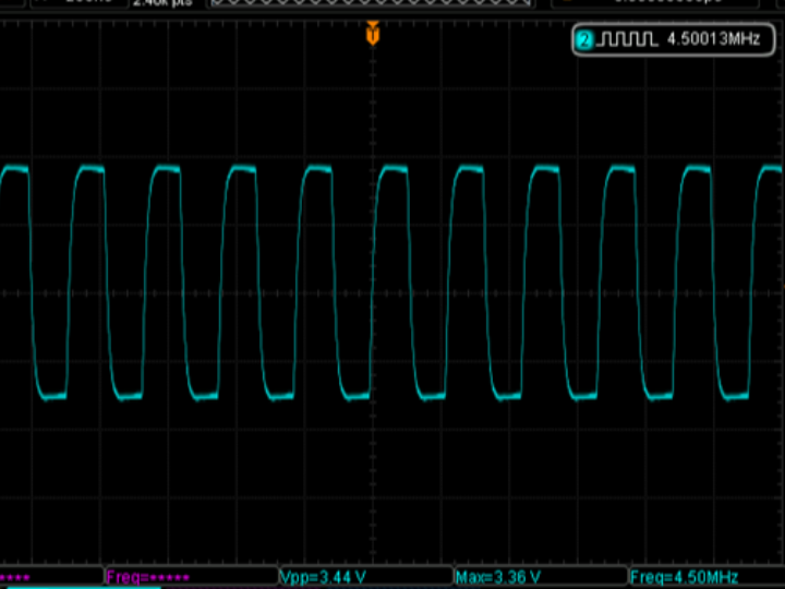
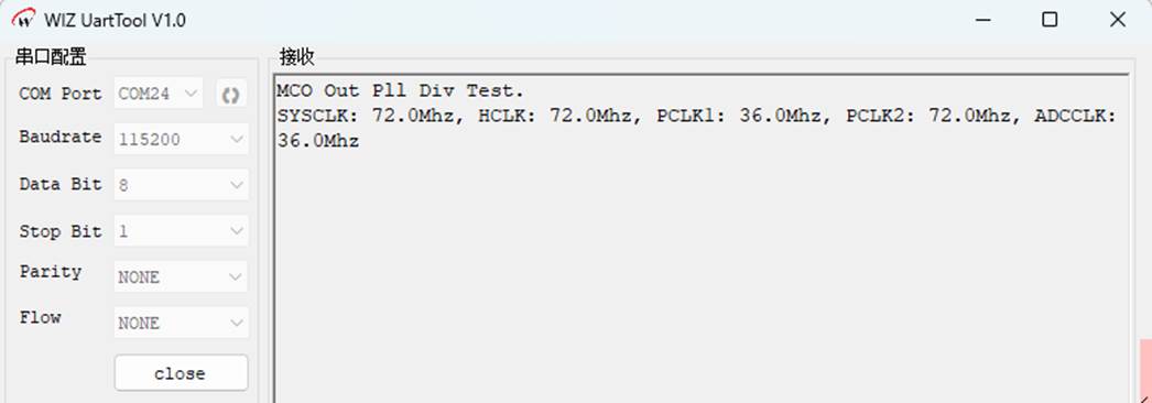
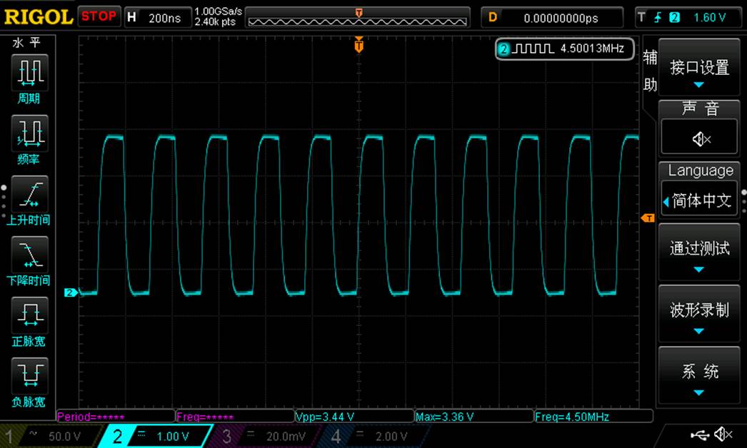
The program first initializes the delay function and the system clock, configures the UART to output debugging information at a baud rate of 115200, then obtains and prints the frequencies of the system clock, AHB bus, APB1/APB2 bus and ADC clock. Next, it configures the MCO pin (PA8) and divides the PLL clock by 16 and outputs it through this pin. Finally, the program enters an infinite loop to maintain the running state.
Download Verification
After the program was downloaded and run, it first printed the name of the example and the frequencies of each system clock, and then the PA8 pin continuously output a waveform:
Summary
The MCO function enables W55MH32 to provide an external output clock by flexibly configuring the clock source and the division factor. This simplifies the clock synchronization issues in the system design. First, understand its application scenarios (such as multi-chip synchronization, debugging and measurement), and then master the configuration steps (clock source selection, GPIO settings, division configuration). This can be applied more efficiently in actual projects.
WIZnet is a non-chipfoundry semiconductor company founded in 1998. Its products include the Internet processor iMCU™, which adopts TOE (TCP/IP Offloading Engine) technology and is based on a unique patented fully hardwired TCP/IP. iMCU™ is designed for embedded Internet devices in various applications.
WIZnet has over 70 distributors worldwide, with offices in Hong Kong, South Korea, and the United States, providing technical support and product marketing.
The region managed by the Hong Kong office includes: Australia, India, Turkey, and Asia (excluding South Korea and Japan).