
Chapter 30: W55MH32’s The Compilation Process and File Types of MDK
Chapter 30: W55MH32’s The Compilation Process and File Types of MDK
Chapter 30: W55MH32’s The Compilation Process and File Types of MDK
It is believed that you have become very proficient in using MDK to create applications. Usually, you write source code using MDK, then compile it to generate machine code, and finally download the machine code onto the STM32 chip for execution. But what exactly does MDK do during this compilation and download process? What are the functions of the various files generated after compilation? This chapter will explain these processes. Understanding the compilation and download process is helpful for understanding the working principle of the chip. This knowledge is very important when creating IAP (bootloader) and reading/writing the internal FLASH of the controller.
1 Compilation process
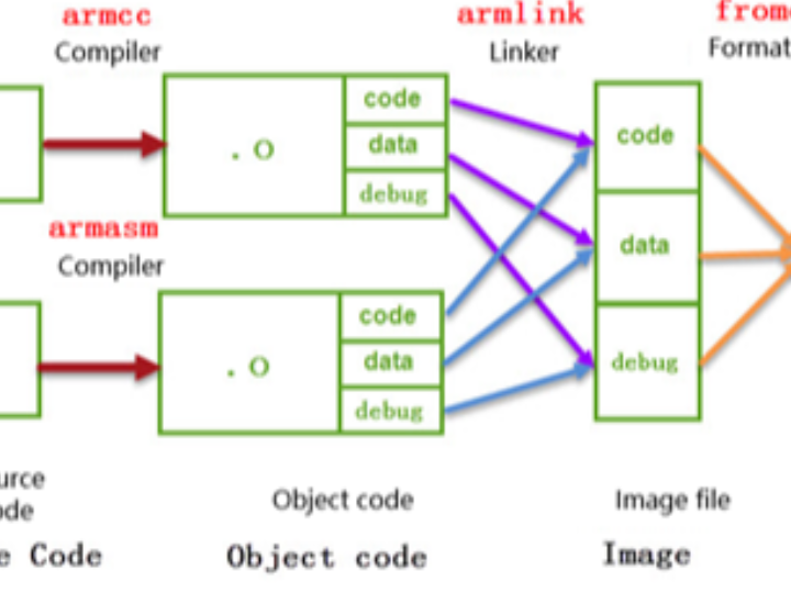
First, let's briefly understand the compilation process of MDK. It is similar to the working process of other compilers. The process is shown in the figure.
The different files generated during the compilation process will be elaborated on in the following sections. For now, let's focus on the main process to understand it.
(1) Compilation: The compiler used by the MDK software is armcc and armasm. They convert each C/C++ and assembly source file into corresponding object files with the suffix ".o" (Object Code, also known as target files). The content mainly consists of the machine code compiled from the source files, including code, data, and debugging information;
(2) Linking: The linker armlink links each.o file and library files into an image file ".axf" or ".elf";
(3) Format Conversion: Generally, in Windows or Linux systems, the linker directly generates an executable image file "elf", and the kernel loads it based on the information in the file, allowing the program to run. However, on a single-chip microcontroller platform, the content of this file needs to be loaded onto the chip, so a format converter fromelf is used to convert the elf image file generated by the linker into a ".bin" or ".hex" file, which is then downloaded to the FLASH or ROM of the chip by the downloader.
2 The composition, storage and execution of the program
2.1 CODE, RO, RW, ZI Data fields and stack space
In the compilation prompt output information of the project, there is a statement "Program Size: Code=xx RO-data=xx RW-data=xx ZI-data=xx", which indicates the size of each domain of the program. After compilation, all data (including the code) with the same nature in the application program are grouped into one domain. During storage or running of the program, different domains will present different states. The meanings of these domains are as follows:
Code: This refers to the code domain, which is the machine instructions generated by the compiler. These contents are stored in the ROM area.
RO-data: Read Only data, also known as the read-only data domain, refers to the read-only data used by the program. This data is stored in the ROM area, so the program cannot modify its content. For example, variables defined with the const keyword in C language are typical RO-data.
RW-data: Read Write data, also known as the read-write data domain, refers to the writable data initialized to "non-zero values". When the program starts running, these data have an initial value of non-zero, and during the running process, they remain in the RAM area, so the application can modify their content. For example, global variables defined in C language and initialized with "non-zero values" when defined are typical RW-data.
ZI-data: Zero Initialized data, also known as the zero-initialized data domain, refers to the writable data initialized to "zero values". The difference between ZI-data and RW-data is that when the program starts running, the initial values of these data are all zero, and during the subsequent running process, they remain in the RAM area, so the application can change their content. For example, global variables defined in C language and initialized with "zero values" (if the variable is not given an initial value when defined, the compiler will treat it as ZI-data and initialize it to 0) are typical ZI-data.
Stack space and heap space of ZI-data: In C language, local variables defined within a function belong to the stack space. When entering the function, memory is allocated from the stack space for the local variables, and when exiting, the local variables are released and the memory space is returned. Variables allocated dynamically using malloc belong to the heap space. Both the stack space and heap space in the program belong to the ZI-data area. These spaces will be initialized to zero values. The space value occupied by ZI-data given by the compiler includes the size of the stack (after actual testing, if there is no use of dynamic allocation of heap space in the program, the compiler will optimize and not include the heap space in the calculation).
Program component | Category |
Machine code instructions | Code |
Constant | RO-data |
Global variables with non-zero initial values | RW-data |
A global variable with an initial value of 0 | ZI-data |
Local variable | ZI-data stack space |
The space allocated dynamically using malloc | ZI-data heap space |
2.2 The storage and execution of the program
The RW-data and ZI-data are merely different in their initial values. Why does the compiler have to distinguish between them? This involves the storage state of the program. An application has a static state and a running state. The static program is stored in non-volatile memory, such as the internal FLASH of STM32, so it can be saved normally even when the system loses power. However, when the program is in the running state, it often needs to modify some temporary data. Due to the requirements of running speed, these data are often stored in memory (RAM), and they will be lost when the power is off. Therefore, the program's performance in the storage medium is different when it is in the static and running states. See the figure
On the left side of the figure is the storage state of the application, on the right side is the running state, and above is the RAM memory area, and below is the ROM memory area.
When the program is in the storage state, both the RO section (RO section) and the RW section are saved in the ROM area. When the program starts running, the kernel directly reads the code from the ROM and, before executing the main code, it first executes a loading code that copies the RW section data from the ROM to the RAM, and then adds the ZI section to the RAM, with the ZI section data initialized to 0. After the loading is completed, the RAM area is ready and the main program starts to execute.
The data of the compiled RW-data belongs to the RW section in the figure, and the data of the ZI-data belongs to the ZI section. The reason for distinguishing RW-data from ZI-data is whether to save it during power-off. Because when creating data in the RAM, the default value is 0. However, if some data requires an initial value other than 0, then the ROM needs to record the initial value and copy it to the RAM during runtime.
The RO area of STM32 does not need to be loaded into SRAM, and the kernel directly reads instructions from FLASH to run. The application running process in a computer system is similar, but in the storage state of the computer system, the program is located on the hard disk, and during execution, it even loads the above-mentioned RO area (code, read-only data) into memory to speed up the running speed, and the virtual memory management unit (MMU) assists in loading data, enabling the execution of applications larger than the physical memory. However, STM32 does not have MMU, so it cannot support Linux and Windows systems.
When the program is stored in the internal FLASH of the STM32 chip (i.e., the ROM area), the space occupied by it is the sum of Code, RO-data, and RW-data. Therefore, if these contents are larger than the FLASH space of the STM32 chip, the program cannot be saved normally. When the program is executing, it needs to occupy the internal SRAM space (i.e., the RAM area), and the occupied space includes RW-data and ZI-data. The composition of each area of the application in various states is shown in the table.
Program status and area | Composition |
The read-only area (RO) during program execution | Code + RO data |
The readable and writable area (RW) during program execution | RW data + ZI data |
The ROM area occupied by the program during storage | Code + RO data + RW data |
In MDK, the projects we create usually involve selecting the chip model. Once the model is chosen, the specific sizes of FLASH and SRAM are determined. If the code exceeds the storage limit of the chip's memory, the compiler will give an error message. At this point, program trimming is necessary. During the trimming process, optimization can be performed specifically for the exceeded areas.
2.3 Compilation toolchain
During the previous compilation process, MDK invoked various compilation tools. Usually, we simply configure MDK without needing to learn how to use them, but understanding them is very beneficial. For instance, if you want to use MDK to compile and generate a bin file, you need to input instructions in MDK to control the fromelf tool; when explaining AXF and O files later in this chapter, you need to use the fromelf tool to view the file information, which cannot be directly achieved through MDK. The explanations of these tool chains are detailed in the MDK help manual "ARM Development Tools", and you can open this file by clicking the "help->uVision Help" menu on the MDK interface.
2.3.1 armcc
armcc is used to compile C/C++ files into ARM instruction code. After compilation, it will output an ELF format O file (object, target file). By entering "armcc" in the command line and pressing Enter, this tool can be invoked. It will print out the help instructions, as shown in the help prompt of armcc.
The help prompt is divided into three parts. The first part is the version information of armcc. The second part is the usage of the command. The third part is the main command options.
According to the command usage: armcc [options] file1 file2 …filen. In the [option] position, you can input the following options such as “—arm” and “—cpu list”. If the option is input with a file, then the file name will be filled in the positions of file1, file2… These files are generally C/C++ files.
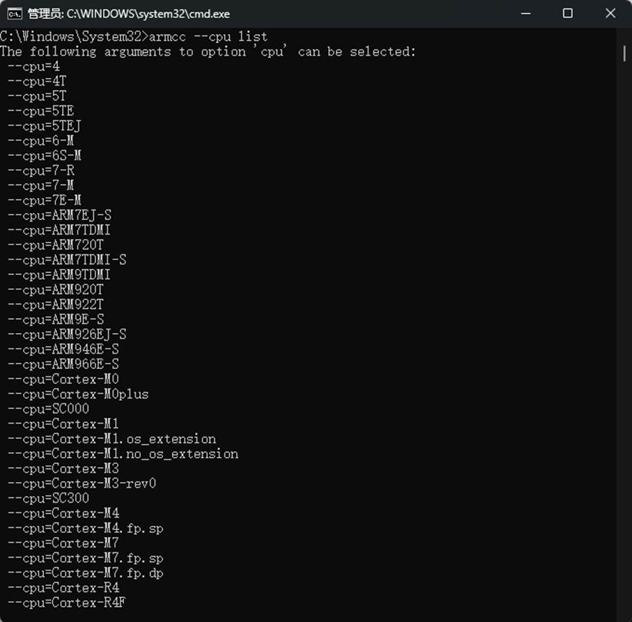
For example, according to its help description, “—cpu list” can list all the CPUs supported by the compiler. We input “armcc —cpu list” in the command line, and you can view the CPU list in the figure.
Open the "Options for Target -> c/c++" menu in MDK, and you can see the control commands for the compiler set by MDK. Refer to the image "ARMCC Compilation Options in MDK" for details.
From the commands in this figure, it can be seen that it has invoked compilation options such as -c, -cpu -D -g -O1. When we modify the compilation configuration of MDK, we can observe that the control command will also change accordingly. However, we cannot input commands in the compilation option box; we can only modify them through the options provided by MDK.
Understanding this, we can then query the specific information of the MDK compilation options. For example, what is the function of "Optimization: Level 1 (-O1)" in the C/C++ options? First, we can learn that it is the "-O" command, followed by a number. By referring to the help manual of MDK, in the section of ARMCC compiler instructions, we can have a detailed understanding. As shown in the figure, Compiler Option Description.
Using MDK, we usually don't need to manually invoke the armcc tool ourselves. However, through this process, we will gain a deeper understanding of MDK and won't be so troubled by its various compilation options.
2.3.2 armasm
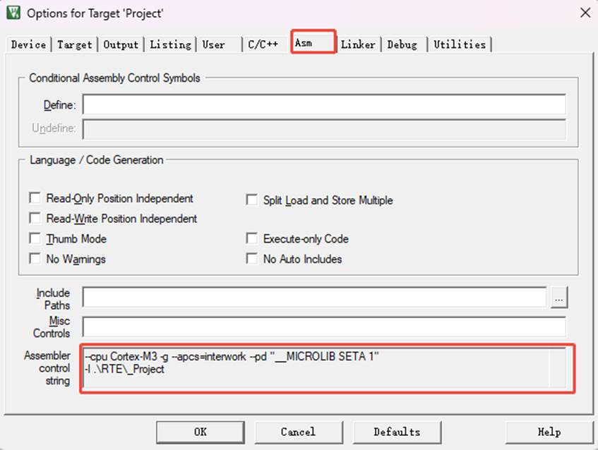
Armasm is an assembler that converts assembly files into O files. Similar to armcc, the calling options for armasm in MDK can be configured on the "Option for Target -> Asm" page. See the compilation options of armasm and MDK in the figure.
2.3.3 armlink
Armlink is a linker that combines various O files to generate an ELF format AXF file. The AXF file is executable. The downloader downloads the instruction codes in this file to the chip, and then the chip can run the program. Using armlink, it is also possible to control the program to be stored at a specified ROM or RAM address. In MDK, the armlink options can be configured on the "Option for Target -> Linker" page. See the configuration options of armlink and MDK in the figure.
The linker by default generates the program based on the memory distribution of the chip type. This memory distribution is recorded in the file with the "sct" suffix in the project. If there are special needs, you can edit this file yourself to change the linking method of the linker. We will explain the details later.
2.3.4 Armar, Fromelf and User Instructions
The Armar tool is used to package the project into library files. Fromelf can generate hex and bin files based on axf files. Hex and bin files are the download file formats supported by most downloaders.
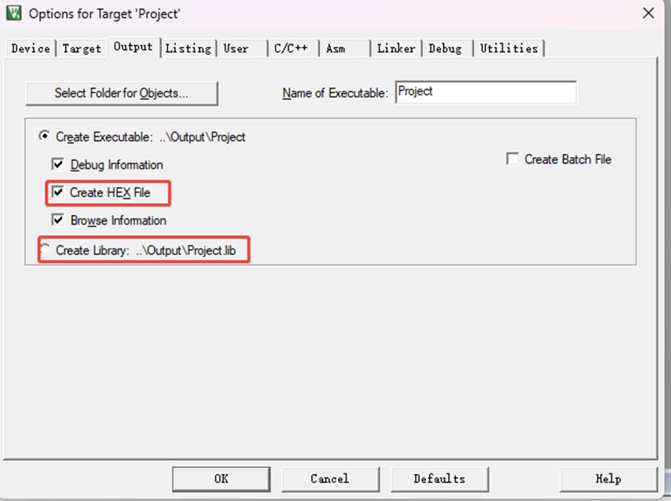
In MDK, there are very few options for the Armar and Fromelf tools. Only the options for generating HEX or Lib are integrated. See the figure for the configuration to control Fromelf to generate hex and control Armar to generate lib.
For example, if we want to generate a bin file using fromelf, we can add the instruction to call fromelf in the "Option for Target -> User" page of MDK, as shown in the figure. Add the instruction in MDK.
On the User configuration page, there are three types of user instruction input boxes. By inputting instructions in different groups, you can control the execution time of the instructions, which are before compilation (Before Compile c/c++ file), before building (Before Build/Rebuild), and after building (After Build/Rebuild). These instructions are not restricted to having to be for the ARM compilation toolchain. For example, if you have written your own Python script, you can also input the user instructions to execute the script here.
The instruction for generating the bin file in the figure calls the fromelf tool, followed by the options of the tool and the output file name, input file name. Since fromelf generates bin based on axf files, and axf files are generated after the build (build) project, we placed this instruction in the "After Build/Rebuild" column.
3.File types of the MDK project
In addition to the files generated during the above compilation process, the MDK project also contains various other files. We will introduce them all together. The common file types of the MDK project are shown in the table. Common file types of MDK
Suffix | Explanation |
*.uvguix | The window layout file of the MDK5 project has the same function as the files with the *.UVGUI extension in MDK4. |
*.uvprojx | The engineering file of MDK5 uses XML format to record the engineering structure. Double-clicking it can open the entire project. In MDK4, files with the *.UVPROJ extension have the same function. |
*.uvoptx | The engineering configuration options of MDK5 include debugger, trace configuration, breakpoints, and the currently opened files. The functions of files with the *.UVOPT suffix in MDK4 are the same. |
*.ini | The configuration record files of some downloaders |
*.c | C language source file |
*.cpp | C++ source file |
*.h | Header files of C/C++ |
*.s | Source file of assembly language |
*.inc | Header files for assembly language (included using "$include") |
*.lib | Library file |
*.dep | The dependent files of the entire project |
*.d | Describes the files that are dependencies for the corresponding.o |
*.crf | Cross-reference file, which contains browsing information (definitions, references and identifiers) |
*.o | Relocatable object file (object file) |
*.bin | The binary format image file is a pure FLASH image and does not contain any additional information. |
*.hex | The Intel Hex format image file can be regarded as a bin file with storage address description format. |
*.elf | The files generated by GCC have the same functions as axf files, but these files are non-relocatable. |
*.axf | The executable object file generated by ARMCC can be used for debugging, but this file cannot be re-targeted. |
*.sct | Linker control file (distributed loading) |
*.scr | The scattered loading files generated by the linker |
*.lnp | The link input file generated by MDK, used for inputting commands when invoking the linker |
*.htm | The static call graph file generated by the linker |
*.build_log.htm | The log recording file of the construction project |
*.lst | List files generated by C and assembly compilers |
*.map | The list file generated by the linker, which contains the distribution of the memory image |
*.ini | Simulation, downloader's script file |
These files are mainly divided into MDK-related files, source files, and files generated by the compiler and linker. We will explain the functions of various files by taking the "Colorful Waterfall Lamp" project as an example.
4 Source file
The source files are the most familiar elements in the project. They are all the various source codes we have written. MDK supports source code files of types such as c, cpp, h, s, and inc. Among them, c and cpp are source codes of the C/C++ languages, h is their header files, s is assembly files, and inc is the header files of assembly files. They can be included using the "$include" syntax. The compiler generates machine code based on the source files in the project.
4.1 The files generated in the "Output" directory
Click the "Compile" button in MDK. It will generate various object and list files based on the configuration of the project and the source files within the project. Configure their output paths in the "Options for Target -> Output -> Select Folder for Objects" and "Options for Target -> Listing -> Select Folder for Listings" options. Refer to the figure for "Setting Output Path" and the figure for "Setting Listing Path".
4.2 lib library file
In some cases, we want to provide a usable code library to a third party, but we do not want them to see the source code. At this time, we can provide the project as a lib file (Library file) to them. In MDK, the "Options for Target -> Create Library" option can be configured to compile the project into a library file. See the figure to generate the library file or executable file.
In the project, you can only choose to generate either an executable file or a library file. By default, the executable file is generated. The executable file is the machine code that we download onto the chip and run directly.
After obtaining the generated *.lib file, you can add it to other projects just like a C file. And in this project, you can call the function interfaces provided by the lib. Apart from not being able to see the source code of the *.lib file, in terms of application, it has no difference from C source files.
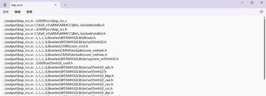
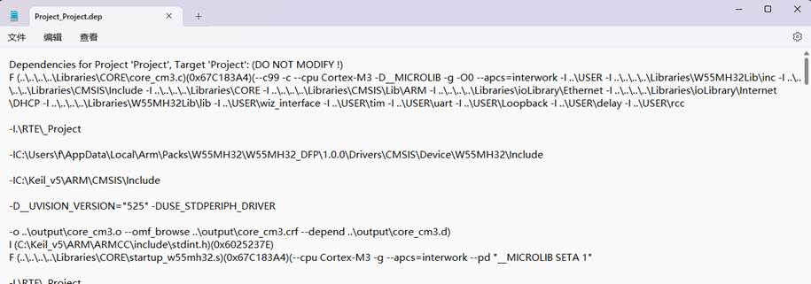
4.3 Dep, d dependency file
*.dep and *.d files (Dependency files) record the dependencies of the project or other files. They mainly record the paths of the included header files. Among them, *.dep represents the dependencies of the entire project, which is named after the project name, while *.d represents the dependencies of individual source files, which are named after the corresponding source file names. These records are stored in text format and can be directly opened using Notepad. See the content of the dep files in the project and the content of the bsp_led_d file.
WIZnet is a fabless semiconductor company founded in 1998. Its products include the Internet processor iMCU™, which utilizes TOE (TCP/IP Offload Engine) technology and is based on a unique patented fully hardwired TCP/IP. The iMCU™ is designed for embedded Internet devices in various applications.
WIZnet has more than 70 distributors globally and has offices in Hong Kong, South Korea, and the United States, providing technical support and product marketing services.
The regions managed by the Hong Kong office include Australia, India, Turkey, and Asia (excluding South Korea and Japan).