
Chapter 28: W55MH32’s RTC - Real-Time Clock
Chapter 28: W55MH32’s RTC - Real-Time Clock
Chapter 28: W55MH32’s RTC - Real-Time Clock
References for this chapter: "W55MH32 Data Manual", "W55MH32 Reference Manual" - "Power Control PWR" and "Real-Time Clock RTC" sections.
1 Introduction to RTC Real-Time Clock
The RTC peripheral (Real Time Clock) of W55MH32 is essentially a timer that continues to operate even when the power is off. From the perspective of the timer, compared to the general timer TIM peripheral, it is very simple, only having the functions of pure timing and triggering interrupts; but from the perspective of continuing to operate even when the power is off, it is the only peripheral in W55MH32 with such powerful functions. Therefore, the complexity of the RTC peripheral does not lie in its timing function, but in its characteristic of continuing to operate even when the power is off.
The power-off mentioned above refers to the situation where the main power VDD is disconnected. To enable the RTC peripheral to continue operating even when the power is off, a lithium battery must be connected to supply power to the RTC and backup card through the VBAT pin. When the main power VDD is valid, it is powered by VDD; when VDD loses power, it is powered by VBAT. Regardless of which power source is used, the data in the RTC is saved in the backup domain belonging to the RTC. If both the main power VDD and VBAT lose power, all the data saved in the backup domain will be lost. The backup domain includes the registers of the RTC module and 42 16-bit registers that can save user program data even when VDD loses power. These data will not be reset when the system is reset or the power is reset.
From the perspective of the timer characteristics of the RTC, it is a 32-bit counter that can only count upwards. It has three clock sources, namely the 128-frequency division of the high-speed external clock (HSE/128), the low-speed internal clock LSI, and the low-speed external clock LSE. When using the HSE divided-frequency clock or LSI, if the main power VDD loses power, both of these clock sources will be affected, so it is impossible to ensure the normal operation of the RTC. Therefore, RTC generally uses the low-speed external clock LSE. In the design, the frequency is usually 32.768KHz, which is the commonly used frequency in real-time clock modules. This is because 32768 = 2 to the power of 15, and frequency division is easy to implement, so it is widely used in RTC modules. When the main power VDD is valid (standby), the RTC can also configure alarm events to make W55MH32 exit the standby mode.
2 Analysis of the RTC Peripheral Block Diagram
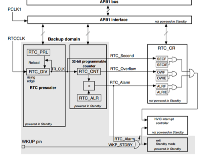
The block diagram of the RTC peripheral is as follows:
The light gray parts in the block diagram belong to the backup domain. In the event of a VDD power failure, they can continue to operate under the drive of VBAT. This part only includes the divider, counter, and alarm controller of the RTC. If the VDD power is valid, the RTC can trigger RTC_Second (second interrupt), RTC_Overflow (overflow event), and RTC_Alarm (alarm interrupt). From the structure diagram, it can be analyzed that the timer overflow event cannot be configured as an interrupt. If the W55MH32 was originally in the standby state, it can exit the standby mode by the alarm event or the WKUP event (an external wake-up event, belonging to the EXTI module, not belonging to the RTC). The alarm event is triggered when the value of the counter RTC_CNT is equal to the value of the alarm register RTC_ALR.
In the backup domain, all registers are 16-bit, and the RTC control-related registers are no exception. The 32-bit counter RTC_CNT of it is composed of two registers, RTC_CNTL and RTC_CNTH, which respectively store the low 16 bits and high 16 bits of the timing count value. When configuring the clock of the RTC module, usually the 32768Hz RTCCLK is divided by 32768 to obtain the actual driving counter clock TR_CLK = RTCCLK/32768 = 1 Hz, with a timing period of 1 second. The counter RTC_CNT counts under the drive of TR_CLK, that is, the value of RTC_CNT is incremented by 1 every second.
Due to the existence of the backup domain, the RTC core has the characteristic of being completely independent of the APB1 interface. Therefore, the access to RTC registers must follow certain rules.
After the system is reset, by default, access to the backup registers and RTC is prohibited to prevent accidental write operations to the backup area (BKP). To enable access to the backup registers and RTC, perform the following operations:
Set the PWREN and BKPEN bits in the RCC_APB1ENR register to enable the power and backup interface clock.
Set the DBP bit in the PWR_CR register to enable access to the backup registers and RTC.
After making the backup registers accessible, when the first time accessing RTC through the APB1 interface, due to the difference in clock frequencies, it is necessary to wait for the APB1 and RTC peripheral to synchronize, ensuring that the value of the RTC register read is correct. If after synchronization, the RTC peripheral interface of APB1 is not closed, there is no need to synchronize again.
If the kernel needs to perform any write operation on the RTC registers, after the kernel issues a write instruction, the RTC module starts the formal write to the RTC registers after 3 RTCCLK clock cycles. Since the frequency of RTCCLK is much lower than the main frequency of the kernel, after each operation, the RTC shutdown operation flag RTOFF must be checked. When this flag is set to 1, the write operation is officially completed.
Of course, all the above operations have library functions, and readers do not need to specifically consult the registers.
3 UNIX timestamp
Before using the RTC peripheral, the concept of UNIX timestamp needs to be introduced.
If we set the counter RTC_CNT to 0 from now on and increment it by 1 every second, when will RTC_CNT overflow? Since RTC_CNT is a 32-bit register, the maximum value it can store is (2^32 - 1), that is, if we count time in this way, it will overflow after 2^32 seconds, that is, it will overflow in about 136 years from now:
N = 2^32 / (365 * 24 * 60 * 60) ≈ 136 years
Suppose at a certain moment the counter value is X = 60 * 60 * 24 * 2, that is, the number of seconds for two days, and suppose we also know that the counter was set to 0 at 0:00:00 on January 1, 2011, then based on this relative time value of the counter, we can calculate that this X moment is 0:00:00 on January 3, 2011. And the counter will overflow around (2011 + 136) years, that is, if we are still using this counter to provide time in the year (2011 + 136), there will be problems:
In this example, the time when the timer is set to 0 is called the time of the calendar year, and the number of seconds passed relative to the calendar year is called the timestamp, that is, the value in the counter.
Most operating systems use timestamps and calendar years to calculate the current time, and both the timestamp and the calendar year have adopted the same standard - UNIX timestamp and UNIX calendar year. The UNIX calendar year is set to 0:00:00 on January 1, 1970, Greenwich Mean Time, probably to commemorate the era of the birth of UNIX, and the UNIX timestamp is the number of seconds that the current time has passed relative to the UNIX calendar year. Because the UNIX timestamp is mainly used to represent the current time or the log time related to the computer (such as file creation time, log occurrence time, etc.), considering that all computer files cannot be created before 1970, the UNIX timestamp is rarely used to represent time before 1970.
In this timing system, a signed 32-bit integer variable is used to store the UNIX timestamp, that is, the actual available count bits are one less than in our above example, and with this one bit less, the UNIX calendar year is also relatively advanced. This timing method will overflow at 03:14:07 on January 19, 2038, which is not far away from us. Since the UNIX timestamp is widely used in various systems, overflow may cause serious system errors, and at that time, a "Y2K bug" problem may be repeated. Therefore, when designing devices with a long expected lifespan, attention should be paid.
Searching for "UNIX timestamp" on the internet can find some websites that provide the current real-time UNIX timestamp. See the real-time UNIX timestamp displayed by a certain website in the following figure:

4. Library functions related to RTC control
The W55MH32 standard library provides comprehensive functions for RTC control. By using these functions, control can be carried out conveniently. This section will explain these contents.
4.1 Waiting for the clock to synchronize and the operation to complete
The clock in the RTC area is slower than the APB clock. Before accessing, clock synchronization is required. This can be achieved simply by calling the library function RTC_WaitForSynchro(). However, if the registers of RTC are modified, the function RTC_WaitForLastTask() needs to be called to ensure that the data has been written. See the code listing: RTC-1
Waits for Clock Synchronization and Completion of Operations
/**These two library functions achieve the waiting functionality by using a while loop to detect the RSF and RTOFF bits in the RTC control register.
4.2 Enabling the backup domain involves RTC configuration
By default, the backup domain to which the RTC belongs is restricted from access. The access can be enabled using the library function PWR_BackupAccessCmd(), as shown in the code listing: RTC-2 :
Code Listing: RTC-2 Enables Access to Backup Domain
/**This function enables access through the DBP bit of the PWR_CR register. Once enabled, one can access the RTC-related registers. However, if you wish to modify the RTC registers, you also need to further enable the CNF bit of the RTC control register to enable the register configuration. See the code listing: RTC-3:
Code Listing: RTC-3 Entering and Exiting RTC Configuration Mode
void RTC_EnterConfigMode(void)These two library functions respectively provide the configuration modes for entering and exiting the RTC registers. Usually, they are called by the library functions.
4.3 Setting the RTC Clock Divisor
After selecting the clock to be used by the RTC using the RCC-related library functions, the library function RTC_SetPrescaler() can be used for frequency division. Usually, the RTC clock is divided to obtain a 1Hz clock. See code listing: RTC-4:
Code Listing: RTC-4 Setting RTC Clock Division Factor
/**In the function, use RTC_EnterConfigMode() and RTC_ExitConfigMode() to enter and exit the RTC register configuration mode. During the configuration process, write the function parameter PrescalerValue to the PRLH and PRLL registers of the RTC.
4.4 Setting and Retrieving RTC Counter and Alarm Clock
The most important components in the RTC peripheral are the counter and the alarm register. These can be manipulated using the library functions RTC_SetCounter(), RTC_GetCounter(), and RTC_SetAlarm(). See code listing: RTC-5:
Code Listing: RTC-5 Configuring RTC Counter and Alarm Clock
/**Using RTC_SetCounter() allows writing new values to the RTC counter. Usually, these values are set as timestamps to update the time.
The RTC_GetCounter() function is used to obtain the current counter value when the RTC is operating normally to get the current time.
The RTC_SetAlarm() function is used to configure the alarm time. When the value of the counter is equal to the value in the alarm register, an alarm event or interrupt can occur, which can wake up the W55MH32 chip in sleep, stop, and standby modes.
5 Real-time clock
5.1 Code analysis
- Header file inclusion
#include <stdlib.h>This includes the standard library header files stdlib.h, string.h and stdio.h, as well as the custom header files delay.h and w55mh32.h.
- Global variables and function declarations
USART_TypeDef *USART_TEST = USART1;USART_TEST: The specified serial port is USART1.
A series of functions are declared, including serial port configuration, interrupt vector table configuration, clock configuration, RTC configuration, time adjustment, and display.
TimeDisplay: A volatile global variable used to indicate whether the time needs to be displayed.
3. The main() function
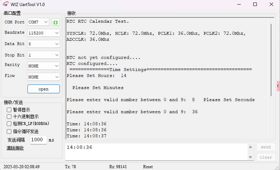
int main(void)
Initialize the delay function delay_init().
Configure the system clock RCC_ClkConfiguration().
Configure the serial port UART_Configuration(115200) and output test information.
Obtain the system clock frequency and output it.
Configure the interrupt vector table NVIC_Configuration().
Check the value of the backup register BKP_DR1. If it is not equal to 0xA5A5, then perform RTC configuration and time adjustment; otherwise, output corresponding information based on the reset flag and enable the RTC second interrupt.
Clear the RCC flag bits.
Enter the Time_Show() function, and display the time in a loop.
Finally, enter an infinite loop.
4. Time_Display() Function
void Time_Display(uint32_t TimeVar)This function is used to convert seconds into hours, minutes and seconds, and output the current time. If the RTC counter reaches 0x0001517F, it will be reset to 0.
5. Time_Show() Function
void Time_Show(void)This function enters an infinite loop. When TimeDisplay is 1, it calls the Time_display() function to display the current time and resets TimeDisplay to 0.
6. RTC_Configuration() Function
void RTC_Configuration(void)
7. USART_Scanf() Function
uint8_t USART_Scanf(uint32_t value)This function is used to read two digital characters from the serial port and convert them into a two-digit integer. If the input characters are not digits or exceed the specified range, it prompts the user to re-enter.
8. Time_Regulate() Function
uint32_t Time_Regulate(void)This function is used to interact with the user via the serial port, allowing the user to set the hour, minute and second, and converting them into seconds before returning the result.
9. Time_Adjust() Function
void Time_Adjust(void)This function is used to adjust the value of the RTC counter. The Time_Regulate() function is called to obtain the time set by the user, and this time is then set in the RTC counter.
10. NVIC_Configuration() Function
void NVIC_Configuration(void)This function is used to configure the interrupt vector table, set the interrupt priority group to NVIC_PriorityGroup_1, and enable the RTC interrupt.
11. UART_Configuration() Function
void UART_Configuration(uint32_t bound)This function is used to configure the serial port USART1, including enabling the clock of USART1 and GPIOA, configuring the GPIO pins, setting the serial port parameters (such as baud rate, data bits, stop bits, parity check, etc.), and enabling the serial port.
12. The SER_PutChar() and fputc() functions
int SER_PutChar(int ch)The SER_PutChar() function is used to send a character to the serial port.
The fputc() function is a function in the standard library for outputting characters. Here, it is redirected to the serial port for output, and a carriage return character is automatically added when outputting a newline character.
5.2 Download verification
6 RTC_LSICalib
6.1 Code Analysis
1. Main function main()
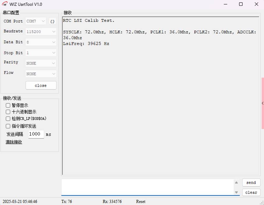
int main(void) {Process: After initializing the serial port, configure the RTC, TIM5 and interrupts, measure the LSI frequency, and finally set the RTC prescaler.
2. TIM5 Configuration(TIM_Configuration)
void TIM_Configuration(void) {Function: Connect the LSI signal to TIM5_CH4, configure TIM5 as an input capture mode, and measure the period of LSI.
3. RTC Configuration (RTC_Configuration)
void RTC_Configuration(void) {Function: Enable LSI, use it as the RTC clock source, configure the RTC prescaler, and output the second signal.
4. NVIC Configuration
void NVIC_Configuration(void) {Function: Set the interrupt priorities of RTC and TIM5 to ensure correct response of interrupts.
This code measures the LSI frequency through TIM5, dynamically configures the pre-divider of RTC to ensure the accuracy of RTC timing, and is suitable for embedded scenarios that require LSI calibration, such as RTC clock source calibration.
6.2 Download verification
WIZnet is a fabless semiconductor company founded in 1998. Its products include the Internet processor iMCU™, which utilizes TOE (TCP/IP Offload Engine) technology and is based on a unique patented fully hardwired TCP/IP. The iMCU™ is designed for embedded Internet devices in various applications.
WIZnet has more than 70 distributors globally and has offices in Hong Kong, South Korea, and the United States, providing technical support and product marketing services.
The regions managed by the Hong Kong office include Australia, India, Turkey, and Asia (excluding South Korea and Japan).