
Chapter 25: W55MH32’s SDIO - SD Card Read/Write Test
Chapter 25: W55MH32’s SDIO - SD Card Read/Write Test
Chapter 25: W55MH32’s SDIO - SD Card Read/Write Test
References for this chapter: "W55MH32 Reference Manual", "SD Simple Specification Document" - "Physical Layer Simplified Specification V2.0" (version number: 2.00).
Before reading the content of this chapter, it is recommended to first read the SD simple specification document.
1 SDIO Introduction
SD cards (Secure Digital Memory Cards) have become very common in our lives. The controller for SD cards typically has two communication interfaces available for reading and writing operations, one being the SPI interface, and the other being the SDIO interface. SDIO stands for Secure Digital Input/Output Interface. Multimedia cards (MMC), SD cards, and SD I/O cards all have SDIO interfaces. The W55MH32 series controller has an SDIO host interface, which can perform data transmission with MMC cards, SD cards, SD I/O cards, and CE-ATA devices. MMC cards can be considered the predecessors of SD cards, and they are rarely used nowadays. SD I/O cards themselves are not storage cards; they are peripherals that use the SDIO transmission protocol. For example, Wi-Fi Card mainly provides Wi-Fi functionality. Some Wi-Fi modules communicate using serial ports or SPI interfaces, but Wi-Fi SDIO Card communicates using the SDIO interface. Generally, SD I/O cards can be inserted into the SD slot. CE-ATA is a high-speed communication interface specifically designed for thin and light notebook hard drives.
The Multimedia Card Association website www.mmca.org provides the multimedia card system specifications issued by the MMCA Technical Committee.
The SD Card Association website www.sdcard.org provides the SD storage card and SDIO card system specifications.
The CE-ATA Working Group website www.ce-ata.org provides the CE_ATA system specifications.
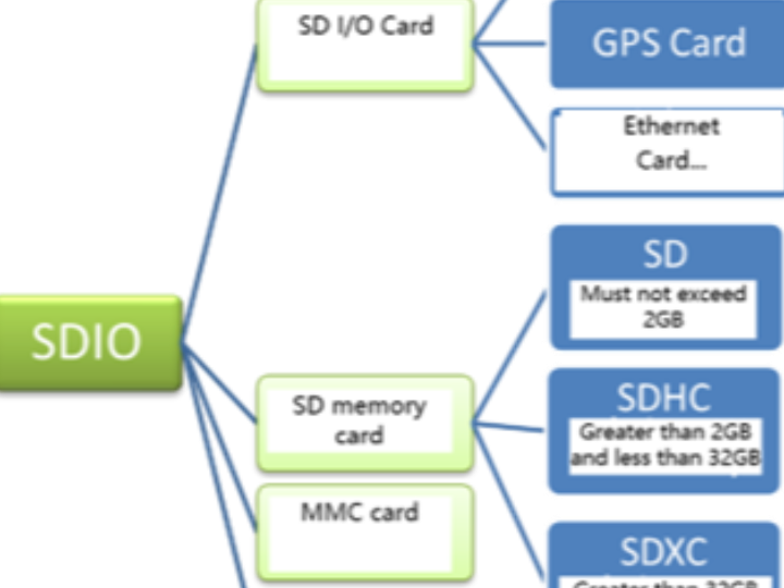
With the development of technology, the demand for SD card capacity is increasing. SD cards have several versions up to now. A general overview of devices with SDIO interfaces is as follows: SDIO interface devices:
For details on SD cards and SD I/O, you can find comprehensive information on the SD Association website, such as various SD card size rules, read/write speed marking methods, application extensions, and other information.
This chapter focuses on the use of SD cards. For the application of other types of cards, you can refer to the relevant system specifications to implement. Therefore, for the content related to other types of cards in the controller, it may be briefly mentioned or ignored in this chapter. The content of this chapter does not distinguish between the concepts of SDIO and SD cards. Even though the latest version of the SD protocol provided for SD cards is 4.01, the W55MH32 series controller only supports SD card specification version 2.0, which only supports standard capacity SD and high capacity SDHC standard cards, and does not support ultra-large capacity SDXC standard cards. Therefore, the highest card capacity that can be supported is 32GB.
2 Physical structure of SD card
An SD card consists of five parts: storage unit, storage unit interface, power detection, card and interface controller, and interface driver. Refer to the following figure for the physical structure of the SD card. The storage unit is the data storage component, and it transmits data with the card control unit through the storage unit interface; the power detection unit ensures that the SD card operates at the appropriate voltage. If there is a power loss or abnormal state, it will reset the control unit and the storage unit interface; the card and interface control unit controls the operating status of the SD card, and it includes 8 registers; the interface driver controls the input and output of the SD card pins.
The SD card has a total of 8 registers, which are used to set or represent SD card information. Refer to the table "SD Card Registers". These registers can only be accessed through corresponding commands. Controlling the SD card is not like operating the GPIO-related registers of the controller, where one reads and writes one register at a time. It is controlled through commands. SDIO defines 64 commands, each with a specific meaning, and can achieve a specific function. After the SD card receives the command, it modifies the internal registers of the SD card according to the requirements of the command. In the program control, only sending a combined command can achieve the control and read/write operations of the SD card.
Name | Bit width | Description |
CID | 128 | Card Identification Number: The unique individual number used for identifying the card. |
RCA | 16 | Relative Address (Relative Card Address): The local system address of the card. During initialization, it is dynamically suggested by the card and approved by the host. |
DSR | 16 | Driver stage register (Driver Stage Register): Output driver configuration of the card |
CSD | 128 | Card-specific data (Card Specific Data): Information regarding the operating conditions of the card |
SCR | 64 | SD Configuration Register (SD Configuration Register): Special characteristics information of SD card |
OCR | 32 | Operation Conditions Register |
SSR | 512 | SD status (SD Status): Information regarding the unique characteristics of the SD card |
CSR | 32 | Card Status: Card Status Information |
The meaning of each register bit can be referred to in Chapter 5 of the SD Simple Specification Document "Physical Layer Simplified Specification V2.0".
3 SDIO bus
3.1 Bus topology
SD cards generally support both SDIO and SPI interfaces. The content of this chapter only introduces the operation method of SDIO interface. If you need to use SPI operation mode, you can refer to the related chapters on SPI. Additionally, the SDIO of the W55MH32 series controller does not support SPI communication mode. If you need to use SPI communication, you can only use the SPI peripheral.
SD card bus topology reference diagram SD card bus topology. Although the buses can be shared, it is not recommended to share the bus signals among multiple card slots. Each separate SD bus should be connected to a separate SD card.
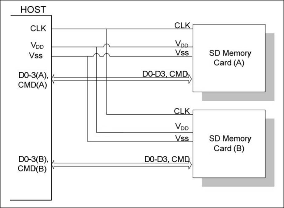
The SD card uses a 9-pin interface for communication. It consists of 3 power lines, 1 clock line, 1 command line, and 4 data lines. The detailed description is as follows:
CLK: Clock line, generated by the SDIO host, that is, output by the W55MH32 controller;
CMD: Command control line, through which the SDIO host sends commands to control the SD card. If the command requires the SD card to provide a response (response), the SD card also transmits the response information through this line;
D0-3: Data lines, for transmitting read and write data; the SD card can pull D0 low to indicate a busy state;
VDD, VSS1, VSS2: Power and ground signals.
In the previous sections on I2C and SPI, the corresponding communication timing sequences have been explained in detail. In fact, the communication timing sequence of SDIO is much simpler. Whether SDIO transmits from the host controller to the SD card or from the SD card to the host controller, it is only the rising edge of the CLK clock line that is valid. The SD card operation process uses two different frequencies of clocks to synchronize data, one is the identification card stage clock frequency FOD, which is the highest at 400kHz, and the other is the data transmission mode clock frequency FPP, which is the default highest at 25MHz. If the SDIO is configured to work in high-speed mode through relevant registers, the highest frequency of the data transmission mode is 50MHz.
For the W55MH32 controller, there is only one SDIO host, so it can only connect to one SDIO device. The development board integrates a Micro SD card slot and an SDIO interface WiFi module, and requires that only one of these devices can be used. The WiFi module of the SDIO interface generally integrates an enable line. If you need to use the SD card, you need to first control this enable line to disable the WiFi module.
3.2 Bus protocol
SD bus communication is based on command and data transmission. The communication starts with a start bit ("0") and ends with a stop bit ("1"). SD communication is generally that the host sends a command (Command), and the slave device responds (Response) after receiving the command. If necessary, data transmission will also be involved.
The basic interaction of the SD bus is the command and response interaction. See the following figure: Command and response interaction:
The SD data is transmitted in block (Black) form. The data block length of SDHC cards is generally 512 bytes. Data can be transferred from the host to the card or from the card to the host. Data blocks require CRC bits to ensure successful data transmission. The CRC bits are generated by the SD card system hardware. The W55MH32 controller can control single-line or 4-line transmission. This development board is designed to use 4-line transmission. Figure Multiple Block Write Operation shows an illustration of the operation where the host writes data blocks to the SD card.
SD data transmission supports single-block and multi-block read/write operations, which correspond to different operation commands respectively. Multi-block writing also requires the use of commands to stop the entire writing operation. Before data writing, it is necessary to detect the SD card's busy status, as the process of programming the data into the storage area by the SD card after receiving the data requires a certain amount of operation time. The busy status of the SD card is indicated by pulling down the D0 line.
The data block read operation is similar, except that there is no need for busy status detection.
When using 4 data lines for transmission, 4 bits of data are transmitted each time, and each data line must have a start bit, a stop bit, and a CRC bit. The CRC bit must be checked separately for each data line, and the results are summarized and then fed back to the host through the D0 line after the data transmission is completed.
There are two formats of SD card data packets. One is the conventional data (8-bit wide), which first transmits the low bytes and then the high bytes, while each byte is transmitted first with the high bit and then with the low bit. The illustration of 8-bit wide data packet transmission using 4 data lines is shown in Figure.
Four lines are used for synchronous transmission, with each line transmitting one byte of data, with two bits of the data. The data is sent sequentially in four lines. The DAT3 data line transmits the higher bits, and the DAT0 data line transmits the lower bits.
Another data packet transmission format is the wide-bit data packet format. For the SD card, the wide-bit data packet transmission method is to send the content of the SD card SSR (SD status) register. The SSR register has a total of 512 bits. After the host issues the ACMD13 command, the SD card will send the content of the SSR register through the DAT lines to the host. The illustration of the wide-bit data packet format is shown below, and the transmission of the wide-bit data packet:
3.3 Command
The SD command is issued by the host. Taking broadcast command and addressing command as examples, the broadcast command is sent to all slave devices connected to the SD host bus, while the addressing command specifies a device with a certain address for command transmission.
3.3.1 Command Format
The SD command format is fixed at 48 bits and is transmitted continuously through the CMD line (the data line is not involved). See the figure below. SD command format:
The composition of the SD command is as follows:
Start bit and stop bit: The command body is contained between the start bit and the stop bit. Both of them only contain one data bit. The start bit is 0 and the stop bit is 1.
Transmission flag: It is used to distinguish the transmission direction. When this bit is 1, it indicates a command, and the direction is from the host to the SD card. When this bit is 0, it indicates a response, and the direction is from the SD card to the host.
The command body content includes three parts: command, address information/parameters, and CRC check.
Command number: It occupies 6 bits fixedly, so there are a total of 64 commands (codes: CMD0 to CMD63). Each command has a specific purpose. Some commands are not applicable to SD card operations and are only used for MMC cards or SD I/O cards.
Address/parameters: Each command has 32-bit address information/parameters for additional command content. For example, broadcast commands have no address information, and these 32 bits are used to specify the parameters, while addressing commands have these 32 bits used to specify the address of the target SD card.
CRC7 check: A 7-bit check bit of the length is used to verify the correctness of the command transmission content. If external interference causes individual bit states of the transmitted data to change, it will lead to calibration failure, which also means the command transmission failure, and the SD card will not execute the command.
3.3.2 Command Types
There are four types of SD commands:
● Non-responsive broadcast command (bc), sent to all cards, without returning task responses;
● With-response broadcast command (bcr), sent to all cards, and simultaneously receiving responses from all cards;
● Addressing command (ac), sent to the selected card, with no data transmission on the DAT line;
● Addressing data transmission command (adtc), sent to the selected card, with data transmission on the DAT line.
In addition, the SD card host module system is designed to provide a standard interface for various application types. In this environment, specific customer/application functions are required. To achieve these functions, two types of general commands of the standard are defined: specific application commands (ACMD) and general commands (GEN_CMD). To use SD card manufacturer-specific ACMD commands such as ACMD6, the CMD55 command must be sent before sending this command, informing the SD card that the next command is a specific application command. The CMD55 command is only effective for the immediately following command. If the SD card detects that the first command after CMD55 is an ACMD command, it will execute its specific application function. If it detects that it is not an ACMD command, it will execute the standard command.
3.3.3 Command Description
The commands of the SD card system are divided into multiple categories, and each category supports a "card function setting". The table "SD Part Commands Description" lists the command information of the SD card section. For more detailed information, you can refer to the SD Simple Specification Document. The fill-in bits and reserved bits in the table must be set to 0.
Although it is not necessary to memorize the detailed information of each command completely, the more familiar you are with the commands, the more helpful it will be for your understanding of the subsequent programming.
Command Number | Type | Parameters | Response | Abbreviation | Description |
CMD0 | bc | [31:0] Filler bit | -- | GO_IDLE_STATE | Reset all the cards to the idle state. |
CMD2 | bcr | [31:0] Filler bit | R2 | ALL_SEND_CID | Notify all cards to return the CID value via the CMD line. |
CMD3 | bcr | [31:0] Filler bit | R6 | SEND_RELATIVE_ADDR | Notify all cards to issue the new RCA. |
CMD4 | bc | [31:16]DSR[15:0] Filler bit | -- | SET_DSR | Program the DSR for all cards. |
CMD7 | ac | [31:16]RCA[15:0] Filler bit | R1b | SELECT/DESELECT_CARD | Select / Unselect the RCA address card. |
CMD8 | bcr | [31:12] Retention bit [11:8] VHS [7:0] Check mode | R7 | SEND_IF_COND | Send the conditions for the SD card interface, including the voltage information supported by the host, and inquire whether the card supports it. |
CMD9 | ac | [31:16]RCA[15:0] Filler bit | R2 | SEND_CSD | The selected card transmits the CSD content via the CMD line. |
CMD10 | ac | [31:16]RCA[15:0] Filler bit | R2 | SEND_CID | The selected card transmits the CID content via the CMD line. |
CMD12 | ac | [31:0] Filler bit | R1b | STOP_TRANSMISSION | Force the card to stop transmitting |
CMD13 | ac | [31:16]RCA[15:0] Filler bit | R1 | SEND_STATUS | The selected card transmits its status register via the CMD line. |
CMD15 | ac | [31:16]RCA[15:0] Filler bit | -- | GO_INACTIVE_STATE | Put the selected card into the "inactive" state |
Block-oriented read operation (Class 2) |
|
|
|
|
|
CMD16 | ac | [31:0] Block length padding bit | R1 | SET_BLOCK_LEN | For standard SD cards, the length of the set block command is set. For SDHC cards, the block command length is fixed at 512 bytes. |
CMD17 | adtc | [31:0] Data address | R1 | READ_SINGLE_BLOCK | For standard cards, read the block with the length of SEL_BLOCK_LEN bytes; for SDHC cards, read the block of 512 bytes. |
CMD18 | adtc | [31:0] Data address | R1 | READ_MULTIPLE_BLOCK | Continuously read data blocks from the SD card until interrupted by CMD12. The block length is the same as that of CMD17. |
Block-oriented write operation (Class 4) |
|
|
|
|
|
CMD24 | adtc | [31:0] Data address | R1 | WRITE_BLOCK | For standard cards, write blocks of the length of SEL_BLOCK_LEN bytes; for SDHC cards, write blocks of 512 bytes. |
CMD25 | adtc | [31:0] Data address | R1 | WRITE_MULTIPLE_BLOCK | Continuously write data blocks to the SD card until interrupted by CMD12. Each block has the same length as CMD17. |
CMD27 | adtc | [31:0] Filler bit | R1 | PROGRAM_CSD | Program the programmable bits of CSD |
Erase command (Class 5) |
|
|
|
|
|
CMD32 | ac | [31:0] Filler bit | R1 | ERASE_WR_BLK_START | Set the starting block address for erasure |
CMD33 | ac | [31:0] Filler bit | R1 | ERASE_WR_BLK_END | Set the end block address for erasure |
CMD38 | ac | [31:0] Filler bit | R1b | ERASE | Erase the pre-selected blocks |
Lock command (Class 7) |
|
|
|
|
|
CMD42 | adtc | [31:0] Maintain | R1 | LOCK_UNLOCK | Lock / Unlock SD card |
Specific application command (Class 8) |
|
|
|
|
|
CMD55 | ac | [31:16]RCA[15:0] Filler bit | R1 | APP_CMD | Specify the next command as a specific application command, not a standard command. |
CMD56 | adtc | [31:1] Fill bit [0] read/write | R1 | GEN_CMD | General command, or specific application command used for transmitting data blocks. The lowest bit being 1 indicates reading data, while 0 indicates writing data. |
SD card specific application command |
|
|
|
|
|
ACMD6 | ac | [31:2] Filler bit[1:0] Bus width | R1 | SET_BUS_WIDTH | Define the width of the data bus ('00' = 1 bit, '10' = 4 bits). |
ACMD13 | adtc | [31:0] Filler bit | R1 | SD_STATUS | Send SD status |
ACMD41 | Bcr | [32] Retention bit[30]HCS(OCR[30]) [29:24] Retention bit[23:0] VDD Voltage (OCR[23:0]) | R3 | SD_SEND_OP_COND | The host requires the card to send the support information (HCS) and the contents of the OCR register. |
ACMD51 | adtc | [31:0] Filler bit | R1 | SEND_SCR | Read the configuration register SCR |
3.4 Response
The response is sent from the SD card to the host. Some commands require the SD card to respond, and these responses are mostly used to provide feedback on the SD card's status. There are a total of 7 response types in the SDIO (codes: R1 to R7), among which the SD card does not have types R4 and R5. Specific commands correspond to specific response types. For example, when the host sends the CMD3 command, a response R6 can be obtained. Like the commands, the responses from the SD card are also transmitted continuously through the CMD line. Based on the size of the response content, they can be classified as short responses and long responses. Short responses are 48 bits in length, and only type R2 is a long response, with a length of 136 bits. The specific situations of each type of response are as shown in the table "SD Card Response Types". Except for type R3, all other responses use CRC7 for verification. For type R2, the CRC7 is calculated using the CID and CSD registers internally.
4 The operation modes of the SD card and their switching
4.1 The operation mode of the SD card
The SD card has multiple versions. The W55MH32 controller currently supports the SD card as defined in the "Physical Layer Simplified Specification V2.0". Before the W55MH32 controller performs data reading and writing on the SD card, it needs to identify the type of the card: V1.0 standard card, V2.0 standard card, V2.0 high-capacity card, or an unrecognized card.
The SD card system (including the host and the SD card) defines two operation modes: card identification mode and data transmission mode. After the system is reset, the host is in the card identification mode, searching for available SDIO devices on the bus; at the same time, the SD card is also in the card identification mode until it is recognized by the host, that is, when the SD card receives the SEND_RCA(CMD3) command, it will enter the data transmission mode, and the host will also enter the data transmission mode after all cards on the bus are recognized. In each operation mode, the SD card has several states. Refer to the table "SD Card States and Operation Modes" to switch the card states through command control.

4.2 Card recognition mode
In the card identification mode, the host will reset all SD cards that are in the "card identification mode", confirm their working voltage range, identify the type of the SD card, and obtain the relative address of the SD card (the card relative address is shorter and more convenient for addressing). During the card identification process, it is required that the SD card operates in the state of the identification clock frequency FOD. The state transition of the SD card in the card identification mode is shown in the figure "Card Identification Mode State Transition Diagram".
After the host is powered on, all cards are in an idle state, including those that are currently in an invalid state. The host can also send the GO_IDLE_STATE (CMD0) command to allow all cards to perform a soft reset and enter the idle state, but cards in an invalid state will not be reset.
Before starting to communicate with the cards, the host needs to first determine that both parties are within the mutually supported voltage range. The SD card has a voltage support range, and the current voltage of the host must be within this range to be able to communicate with the card normally. The SEND_IF_COND (CMD8) command is used to verify the card interface operation conditions (mainly voltage support). The card will detect the matching of the operation conditions according to the parameters of the command. If the card supports the host voltage, it will generate a response; otherwise, it will not respond. The host determines the voltage compatibility of the card based on the response content. CMD8 is a new command for SD cards in the standard V2.0 version, so if the host receives a response, it can determine that the card is a V2.0 or higher version SD card.
The SD_SEND_OP_COND (ACMD41) command can identify or reject cards that do not match its voltage range. The VDD voltage parameter of the ACMD41 command is used to set the host's supported voltage range, and the card's response will return the voltage range supported by the card. For cards that respond to CMD8, setting the HCS bit of the ACMD41 command to 1 can test the card's capacity type. If the CCS bit of the card's response is 1, it indicates a high-capacity SD card, otherwise it is a standard card. After responding to ACMD41, the card enters the preparation state, and cards that do not respond to ACMD41 are unavailable cards and enter the invalid state. ACMD41 is an application-specific command, and this command must be sent before CMD55.
ALL_SEND_CID (CMD2) is used to control all cards to return their card identification numbers (CID). Cards in the preparation state will enter the identification state after sending the CID. Then the host sends the SEND_RELATIVE_ADDR (CMD3) command, allowing the card to recommend a relative address (RCA) and respond to the command. This RCA is a 16-bit address, while the CID is a 128-bit address. Using RCA simplifies communication. After receiving CMD3 and responding, the card enters the data transmission mode and is in a standby state. The host enters the data transmission mode after obtaining the RCA of all cards.
4.3 Data Transmission Mode
Only when the SD card system is in the data transmission mode can data reading and writing operations be performed. In the data transmission mode, the host SD clock frequency can be set to FPP, with the default maximum being 25 MHz. The frequency switching can be achieved through the CMD4 command. In the data transmission mode, the SD card state transition process is shown in the figure "Data Transmission Mode Card State Transition".
CMD7 is used to select and deselect the specified card. Cards in the standby state cannot perform data communication as there may be multiple cards on the bus in the standby state. A RCA address target card must be selected to enter the transmission state before data communication can occur. At the same time, the CMD7 command can also make the selected target card return to the standby state.
Data communication in the data transmission mode is point-to-point between the host and the target card through addressing commands. When the card is in the transmission state, the commands described in the SD section of the table can be used to perform data reading, writing, and erasing on the card. CMD12 can interrupt the ongoing data communication and make the card return to the transmission state. CMD0 and CMD15 will terminate any data programming operation and return the card to the identification mode, which may cause the card data to be damaged.
5 The SDIO functional block diagram of W55MH32
The W55MH32 controller has an SDIO, which consists of two parts: the SDIO adapter and the AHB interface. Refer to the figure below for the SDIO functional block diagram. The SDIO adapter provides the SDIO host function, which can provide SD clock, send commands and perform data transmission. The AHB interface is used for the controller to access the registers of the SDIO adapter and can generate interrupt and DMA request signals.
The SDIO uses two clock signals. One is the SDIO adapter clock (SDIOCLK = HCLK = 72 MHz), and the other is the half-frequency of the AHB bus clock (HCLK/2, usually 36 MHz). The adapter registers and FIFO use the clock on the AHB bus side (HCLK/2), while the control unit, command channel, and data channel use the clock on the SDIO adapter side (SDIOCLK).
SDIO_CK is the clock signal used for synchronization between the SDIO interface and the SD card. It uses SDIOCLK as the clock source for SDIO_CK and can be obtained directly by setting the BYPASS mode. In this case, SDIO_CK = SDIOCLK = HCLK. If the BYPASS mode is disabled, the division factor can be controlled by configuring the CLKDIV bit in the clock register, that is, SDIO_CK = SDIOCLK / (2 + CLKDIV) = HCLK / (2 + CLKDIV). When configuring the clock, it should be noted that the clock frequency of the SD card generally should not exceed 25 MHz.
The SDIO of the W55MH32 controller is the master device for MMC cards and SD cards, so it reserves 8 data lines. For SD cards, the maximum number of data lines used is four.
The SDIO adapter is the host part of the SD card system and is an intermediate device for data communication between the W55MH32 controller and the SD card. The SDIO adapter consists of five units, namely the control unit, command path unit, data path unit, register unit, and FIFO. See the following figure. SDIO adapter block diagram:
5.1 Control Unit
The control unit includes power management and clock management functions, and its structure is shown in the figure "SDIO Adapter Control Unit". The power management component will disable the SD card bus output signal during the power-off and power-on phases. The clock management component controls the generation of the CLK line clock signal. It is usually obtained by dividing SDIOCLK.
5.2 Command Path
Command path control command is sent and the response from the card is received. The structure is shown in the following figure. SDIO adapter command path:
Regarding the state transition process of the SDIO adapter, you can refer to the "SD Card Identification Mode State Transition Diagram". When the SD card is in a certain state, the SDIO adapter must be in a specific state corresponding to it. The W55MH32 controller describes the state changes of the SDIO adapter using the Command Path State Machine (CPSM), and has added a waiting timeout detection function to exit from the situation of permanent waiting. The description of CPSM is shown in the following figure, and the CPSM state machine description diagram is:
5.3 Data path
The data path component is responsible for data transmission with the SD card. Its internal structure is shown in the following figure. SDIO adapter data path:
Reference Diagram for SD Card System Data Transmission Status Transition Data Transmission Mode Card Status Transition. The SDIO adapter describes the state changes of the SDIO adapter using the Data Path State Machine (DPSM). A timeout detection function has also been added to exit from the permanent waiting situation. When sending data, the DPSM is in the waiting for transmission (Wait_S) state. If the data FIFO is not empty, the DPSM changes to the sending state and the data path component starts to send data to the card. When receiving data, the DPSM is in the waiting for reception state. When the DPSM receives the start bit, it changes to the reception state and the data path component starts to receive data from the card. The DPSM state machine description is shown in the following figure, DPSM state machine description diagram:
5.4 Data FIFO
The data FIFO (First-In-First-Out) component is a data buffer with a sending and receiving unit. The controller's FIFO includes a 32-bit wide, 32-byte data buffer and sending/receiving logic. The TXACT bit in the SDIO status register (SDIO_STA) is used to indicate that data is currently being sent, while the RXACT bit indicates that data is currently being received. These two bits cannot be both 1 at the same time.
When TXACT is 1, data can be written to the transmission FIFO through the AHB interface.
When RXACT is 1, the receiving FIFO stores the data received from the data path component.
Based on the FIFO empty or full status, the bit values in the SDIO_STA register will be set to 1, and interrupts and DMA requests can be generated.
5.5 Adapter register
The adapter register contains various control registers and status registers for controlling the SDIO peripheral. It has a large amount of content and can be understood through various structures provided by SDIO. The functions of these registers have all been integrated into structures or the ST standard library.
6 SDIO Initialization Structure
The standard library functions have established three initialization structures for the SDIO peripheral, namely the SDIO initialization structure SDIO_InitTypeDef, the SDIO command initialization structure SDIO_CmdInitTypeDef, and the SDIO data initialization structure SDIO_DataInitTypeDef. These structure members are used to set the parameters of the SDIO working environment and are called by the corresponding initialization configuration functions or functional functions of SDIO. These parameters will be written to the corresponding registers of SDIO to achieve the purpose of configuring the SDIO working environment.
The combination of initialization structures and initialization library functions is the essence of the standard library. Understanding the meaning of each member of the initialization structure basically enables one to master the use of the peripheral. The initialization structure is defined in the w55mh32_sdio.h file, and the initialization library function is defined in the w55mh32_sdio.c file. During programming, we can use these two files along with their comments.
The SDIO initialization structure is used to configure the basic working environment of SDIO, such as clock division, clock edge, data width, etc. It is used by the SDIO_Init() function.
Code Listing: SDIO-1 SDIO Initialization Structure
typedef struct {The functions of each structure member are as follows:
SDIO_ClockEdge: Selects the valid edge of the clock signal at the CLK pin for the main clock SDIOCLK. It can be either the rising edge or the falling edge. It sets the value of the NEGEDGE bit in the SDIO_CLKCR register, and usually this value is set to a high level.
SDIO_ClockBypass:Used for clock frequency division bypass. It can be enabled or disabled. It sets the BYPASS bit in the SDIO_CLKCR register. If the bypass is enabled, SDIOCLK directly drives the CLK line to output the clock; if it is disabled, the CLK line outputs the clock using the CLKDIV value in the SDIO_CLKCR register after dividing SDIOCLK. Generally, the clock frequency division bypass is disabled.
SDIO_ClockPowerSave: Energy-saving mode selection. It can be enabled or disabled. It sets the PWRSAV bit in the SDIO_CLKCR register. If the energy-saving mode is enabled, the CLK line has a clock output only when the bus is activated; if it is disabled, the CLK line always outputs the clock.
SDIO_BusWide: Data line width selection. It can be 1-bit data bus, 4-bit data bus, or 8-bit data bus. The system defaults to using the 1-bit data bus. When operating the SD card, in the data transmission mode, generally 4-bit data bus is selected. It sets the WIDBUS bit in the SDIO_CLKCR register.
SDIO_HardwareFlowControl: Hardware flow control selection. It can be enabled or disabled. It sets the HWFC_EN bit in the SDIO_CLKCR register. The hardware flow control function can avoid FIFO sending overflow and underflow errors.
SDIO_ClockDiv: Clock division coefficient. It sets the CLKDIV bit in the SDIO_CLKCR register. Set the clock division coefficient of SDIOCLK and the CLK line output clock:
CLK line clock frequency = SDIOCLK / ([CLKDIV + 2]).
7 SDIO Command Initialization Structure
The SDIO command initialization structure is used to set the relevant information of the command, such as the command number, command parameters, response type, etc. It is used by the SDIO_SendCommand() function.
Code Listing: SDIO-2 SDIO Command Initialization Interface
typedef struct {The descriptions of each structure member are as follows:
SDIO_Argument:This is the command parameter sent to the card as part of the command. It sets the value of the SDIO parameter register (SDIO_ARG).
SDIO_CmdIndex: Command number selection. It sets the value of the CMDINDEX bit in the SDIO command register (SDIO_CMD).
SDIO_Response: Response type. SDIO defines two response types: long response and short response. The corresponding response type is selected based on the command number. SDIO defines four 32-bit SDIO response registers (SDIO_RESPx, where x=1..4), and the short response only uses SDIO_RESP1.
SDIO_Wait: Waiting type selection. There are three states available, one is the no-wait state, with the timeout detection function activated; one is waiting for an interrupt; and the other is waiting for the transmission to complete. It sets the values of the WAITPEND and WAITINT bits in the SDIO_CMD register.
SDIO_CPSM: Command path state machine control. It can be enabled or disabled optionally. It sets the value of the CPSMEN bit in the SDIO_CMD register.
8 SDIO data initialization structure
The SDIO data initialization structure is used to configure parameters for data transmission and reception, such as transmission timeout, data length, transmission mode, etc. It is used by the SDIO_DataConfig() function.
Code Listing: SDIO-3 SDIO Data Initialization Structure
typedef struct {The descriptions of each structure member are as follows:
SDIO_DataTimeOut: Sets the timeout period for data transmission in terms of the bus clock cycle of the card. It determines the value of the SDIO Data Timer register (SDIO_DTIMER). The decrement begins after DPSM enters the Wait_R or busy state, and continues until it reaches 0. If it remains in either of these states, the timeout status flag will be set to 1.
SDIO_DataLength:Sets the transmission data length. It determines the value of the SDIO Data Length register (SDIO_DLEN).
SDIO_DataBlockSize: Sets the data block size. There are various sizes available, and the data blocks required by different commands may be different. It determines the value of the DBLOCKSIZE bit in the SDIO Data Control register (SDIO_DCTRL).
SDIO_TransferDir:Data transfer direction. It can be either a write operation from the host to the card, or a read operation from the card to the host. It determines the value of the DTDIR bit in the SDIO_DCTRL register.
SDIO_TransferMode: Data transfer mode. It can be either data block mode or data stream mode. For SD card operations, the data block type is used. It determines the value of the DTMODE bit in the SDIO_DCTRL register.
SDIO_DPSM: Data Path State Machine Control. It can be enabled or disabled. It determines the value of the DTEN bit in the SDIO_DCTRL register. To achieve data transmission, SDIO_DPSM must be enabled.
9 SD card read/write test
9.1 Code analysis
The SD card file system test program based on W55MH32 uses the FATFS file system library to perform operations such as reading and writing, creating and deleting directories on the SD card. Below is a detailed explanation of the code:
1. Header file inclusion
#include "w55mh32.h"These header files cover hardware-related definitions, standard input/output libraries, SD card drivers, delay functions, and the FATFS file system library.
2. Function declaration
void USART_Config(uint32_t bound);Here, a series of functions are declared, which are used for serial port configuration, command acquisition, display of test list, display of SD card information, and file system testing, etc.
3. Global variable definition
FATFS fs;These variables are used to store FATFS file system objects, file objects, file operation results, the number of read and write operations, and read/write buffers, etc.
4. Main function main()
int main(void)
The functions of the main program are as follows:
Initialize the CRC clock, delay function and serial port.
Print the system clock information.
Display the test list.
Enter an infinite loop, continuously obtain the user input commands, and call the corresponding test functions based on the commands.
5. Test the list function TestList()
void TestList(void)
{This function is used to display the list of options for the SD card test.
6. SD Card Information Display Function SDInfoShow()
void SDInfoShow(void)
{This function is used to display information such as the type, capacity and block size of the SD card.
7.Obtain the command function GetCmd()
uint8_t GetCmd(void)This function is used to check whether the serial port has received data. If it has received data, it will return that data.
8. Serial port configuration function UART_Configuration()
void UART_Configuration(uint32_t bound)This function is used to configure the GPIO pins of the serial port and the serial port parameters.
9. Big data reading and writing test function FatfsBigDataTest()
void FatfsBigDataTest(void)This function is used for conducting tests on the writing of large volumes of data. First, the file system is mounted, then the file is opened, and data is written in a loop.
10. File system testing function FatfsTest()
void FatfsTest(void)
This function is used for formatting the file system, conducting read and write tests. If there is no file system on the SD card, it will be formatted first, and then file reading and writing operations will be performed.
11. Create directory function: CreateDir()
void CreateDir(void)
This function is used to create directories /Dir1, /Dir2 and /Dir1/Dir1_1 on the SD card.
12. Function for deleting directories and files: DeleteDirFile()
void DeleteDirFile(void)
This function is used to delete the directories and files that were previously created.
13. Function for viewing the root directory: ViewRootDir()
void ViewRootDir(void)
14. Serial port character transmission function SER_PutChar() and fputc()
int SER_PutChar(int ch)This code utilizes the FATFS file system library to achieve operations such as reading and writing files on the SD card, creating and deleting directories, and viewing the root directory. It also provides a simple menu interface to facilitate user testing.
9.2 Download Verification
1. The program is powered on and running.
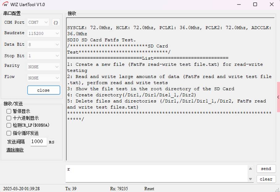
2. Input command for testing
By pressing the number keys (1 to 5) on the keyboard, the corresponding functions can be executed:
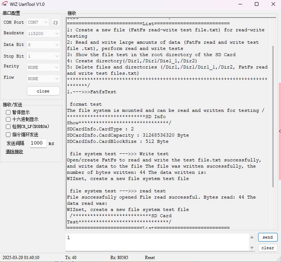
(1) Test 1: Basic File Reading and Writing (Input 1)
Function:
Create file "FatFs read and write test files.txt", write text and then read it back.
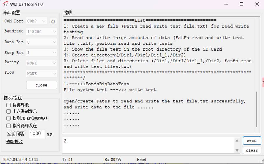
(2) Test 2: Large Data Volume Read and Write (Input 2)
Function:
Write 2MB of data to the file (for stress testing), and output the progress every 36KB written.
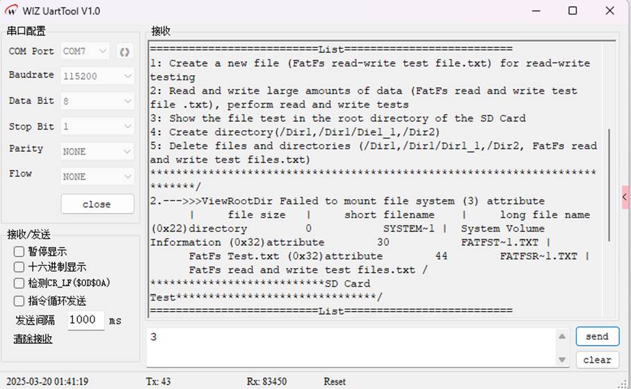
(3) Test 3: View root directory (input 3)
Function:
Display the files and subdirectories in the root directory of the SD card.
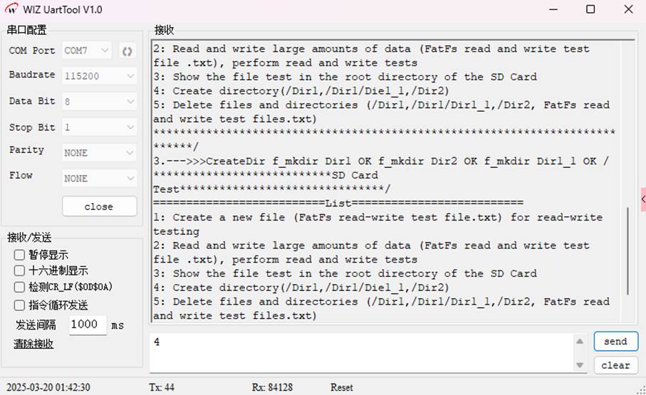
(4) Test 4: Create Directory (Input 4)
Function:
Create the directories /Dir1, /Dir1/Dir1_1, and /Dir2.
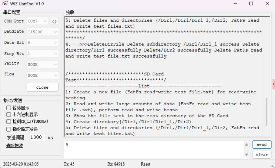
- (5) Test 5: Delete Directory/File (Input 5)
Function:
Delete the test files and directories (make sure the directories are empty).
WIZnet is a fabless semiconductor company founded in 1998. Its products include the Internet processor iMCU™, which utilizes TOE (TCP/IP Offload Engine) technology and is based on a unique patented fully hardwired TCP/IP. The iMCU™ is designed for embedded Internet devices in various applications.
WIZnet has more than 70 distributors globally and has offices in Hong Kong, South Korea, and the United States, providing technical support and product marketing services.
The regions managed by the Hong Kong office include Australia, India, Turkey, and Asia (excluding South Korea and Japan).