
Chapter 24: W55MH32’s WWDG - Window Watchdog
Chapter 24: W55MH32’s WWDG - Window Watchdog
Chapter 24: W55MH32’s WWDG - Window Watchdog
References for this chapter: "W55MH32 Reference Manual" - WWDG section.
When studying this chapter, it will be more effective to read it in conjunction with the WWDG section of the "W55MH32 Reference Manual", especially for the part related to register descriptions.
1 WWDG Introduction
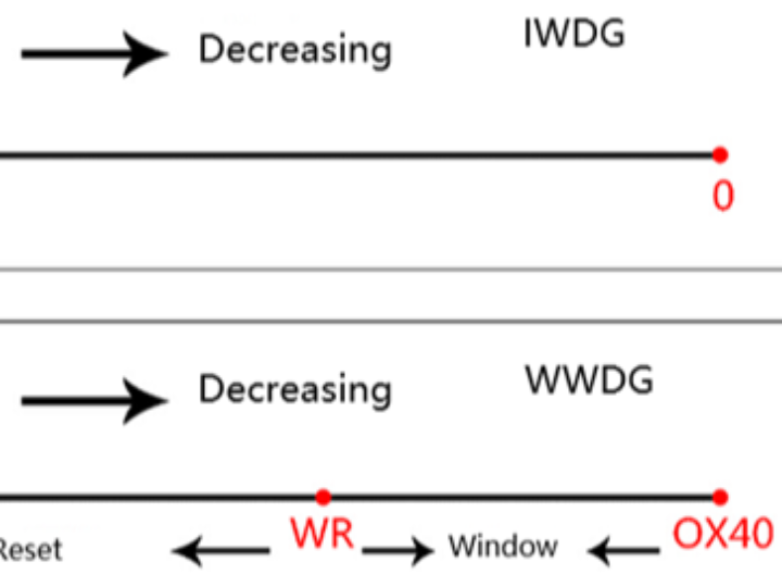
The W55MH32 has two watchdogs, one is an independent watchdog and the other is a window watchdog. We know that the working principle of the independent watchdog is that a decrement counter continuously decreases the count. If the dog is not fed before it reaches 0, a reset will occur. The window watchdog is similar to the independent watchdog. It is also a decrement counter that continuously decreases the count. If the value reaches the fixed value 0X40 before feeding the dog, a reset will occur. This value is called the lower limit of the window and is a fixed value that cannot be changed. This is a similar point to the independent watchdog. The difference is that the value of the counter in the window watchdog will also generate a reset before it reaches a certain number when feeding the dog. This value is called the upper limit of the window and the upper limit value is independently set by the user. The value of the window watchdog counter must be between the upper and lower windows to feed the dog. This is the meaning of the two words "window" in the window watchdog.
RLR is a reload register used to set the counter value of the independent watchdog. TR is the counter value of the window watchdog, which is set independently by the user. WR is the upper window value of the window watchdog, also set independently by the user.
2 Analysis of the WWDG Function Block Diagram
The functional block diagram of WWDG is as follows:
2.1 Window Watchdog Clock
The watchdog timer clock is derived from PCLK1, and the maximum frequency of PCLK1 is 108 MHz. It is enabled by the RCC clock controller.
2.2 Counter clock
The counter clock is obtained by dividing the CK timer clock through a pre-divider. The division factor is configured by the bits 8:7 of the configuration register CFR, which can be [0, 1, 2, 3]. Here, the CK timer clock = PCLK1/4096. Dividing by 4096 is as specified in the manual and there is no reason for it. Therefore, the counter clock CNT_CK = PCLK1/4096 / (2^WDGTB). This allows us to calculate the time T for the counter to decrement by one, which is T = 1 / CNT_CK = Tpclk1 * 4096 * (2^WDGTB).
2.3 Counter
The counter of the window watchdog is a decrementing counter with 7 bits, and its value is stored in the bits 6:0 of the control register CR, namely T[6:0]. When all 7 bits are 1, it is 0X7F, which is the maximum value. When it decrements to T6 becoming 0, that is, from 0X40 to 0X3F, a watchdog reset will occur. The value 0X40 is the minimum value that the watchdog can decrement to, so the counter value can only be: 0X40 to 0X7F. In fact, the value actually used for counting is T[5:0]. When the decrement counter decrements to 0X40, it will not immediately generate a reset. If the early wake-up interrupt is enabled: the bit 9EWI of the CFR is set to 1, then an early wake-up interrupt will occur. If this interrupt actually occurs, it indicates that there must be a problem with the program. Then in the interrupt service program, we need to do the most important work, such as saving important data or giving an alarm, etc. This interrupt is also called the "before death interrupt".
2.4 Window value
We know that the window watchdog must be fed the dog only when the value of the counter is within a certain range. The lower window value is fixed at 0X40, while the upper window value can be changed. The specific value is set by the bit 6:0 W[6:0] of the configuration register CFR. The value must be greater than 0X40. If it is less than or equal to 0X40, the window loses its value, and it cannot be greater than the value of the counter. Therefore, it must be less than 0X7F. What should the window value be set to exactly? This depends on the running time of the program we need to monitor. If the running time of program segment A is Ta, after executing this program segment, the dog feeding should be carried out. If the dog is not fed within the window time, then the program is definitely faulty. Generally, the counter value TR is set to the maximum 0X7F, the window value is WR, and the time for the counter to decrement by one number is T. Then the time: (TR-WR)*T should be slightly less than Ta. This way, the dog can be fed just after executing program segment A, achieving the monitoring function. Thus, the value of WR can be calculated.
2.5 Calculate the watchdog timeout period
This diagram is from the data manual. From the diagram, we can see that the watchdog timeout time: Twwdg = Tpclk1 x 4096 x 2^wdgtb x (T[5:0] + 1) ms. When PCLK1 = 36 MHz, the minimum and maximum timeout times occur when WDGTB takes different values. How should we understand and calculate these minimum and maximum timeout times? It's a bit complicated to explain here. I will briefly explain how to calculate when WDGTB = 0. The decrement counter has 7 bits T[6:0], when bit 6 becomes 0, a reset occurs. In fact, the effective counting bits are T[5:0], and T6 must be set to 1 first. If T[5:0] = 0 when the decrement counter is decremented once more, a reset occurs. The time for this decrement is equal to the counter's period = 1/CNT_CK = Tpclk1 x 4096 x (2^WDGTB) = 1/36 * 4096 * 2^0 = 113.7 us. This is the shortest timeout time. If T[5:0] is all filled with 1, that is, 63, when it reduces to 0X40 and becomes 0X3F, the required time is the maximum timeout time = 113.7 * 2^5 = 113.7 * 64 = 7.2768 ms. Similarly, when WDGTB is equal to 1/2/3, substitute the formula to calculate.
3 WWDG Usage Instructions
WWDG is generally used to monitor software failures caused by external interference or unforeseen logical conditions that cause the application to deviate from its normal operation sequence. For example, a program segment runs normally for 50ms. After running this segment of the program, it immediately proceeds to feed the dog. If the dog is not fed within the specified time window, it indicates that the monitored program has failed and crashed. Then, a system reset will occur, causing the program to restart.
4. Interrupt Test of WWDG
4.1 Code Analysis
It is mainly used for the interrupt test of the Window Watchdog (WWDG). Below is a detailed explanation of each part of the code:
- Header file inclusion
#include <stdlib.h>stdlib.h, string.h and stdio.h are standard C library header files, respectively providing general utility functions, string operation functions and standard input/output capabilities.
delay.h is a custom header file and might be used to implement the delay function.
w55mh32.h is a header file.
2. Global Variable Definition
USART_TypeDef *USART_TEST = USART1;A pointer USART_TEST of type USART_TypeDef was defined and initialized as USART1. Subsequent serial port operations will use USART1.
3. Function Declaration
void UART_Configuration(uint32_t bound);The UART_Configuration() function is used to configure serial communication, with the parameter bound representing the baud rate.
The GetCmd() function is used to receive data from the serial port.
The NVIC_Configuration() function is used to configure the Nested Vectored Interrupt Controller (NVIC).
4. The main() function
int main(void)Define a variable named "clocks" of type RCC_ClocksTypeDef to store the system clock frequency information.
Enable the Watchdog Timer (WWDG) clock.
Call the delay_init() function to initialize the delay functionality.
Call the UART_Configuration() function to configure the serial communication with a baud rate of 115200.
Call the RCC_GetClocksFreq() function to obtain the system clock frequency information and output it via the serial port.
Output a prompt message indicating the window watchdog interrupt test and the use of the interrupt method to feed the watchdog.
Configure the prescaler and window value of the window watchdog, and enable the window watchdog.
Clear the flag of the window watchdog.
Call the NVIC_Configuration() function to configure the NVIC.
Enable the interrupt function of the window watchdog.
Enter an infinite loop where the program pauses.
5. WWDG_IRQHandler() Function
void WWDG_IRQHandler(void)This is the interrupt service function of the window watchdog. When the window watchdog generates an interrupt, this function will be executed. In the function:
The counter value of the window watchdog is set to 0x7f, which is the feeding operation for the watchdog to prevent the system from resetting.
The flag of the window watchdog is cleared so that it can handle the next interrupt.
6. NVIC_Configuration() Function
void NVIC_Configuration(void)7. UART_Configuration() Function
void UART_Configuration(uint32_t bound)This function is used to configure the USART1 serial communication. The specific steps are as follows:
Enable the clocks for USART1 and GPIOA.
Configure Pin 9 of GPIOA as a re-mapped push-pull output mode, serving as the transmission pin of USART1.
Configure Pin 10 of GPIOA as an open-drain input mode, serving as the reception pin of USART1.
Configure the baud rate, data bits, stop bits, parity bit, hardware flow control and working mode of USART1.
Initialize USART1 and enable it.
8. GetCmd() Function
uint8_t GetCmd(void)This function is used to receive data from USART1. If the flag USART_FLAG_RXNE indicating that the receive buffer is not empty is set, then data is read from the receive buffer and returned.
9. SER_PutChar() Function
int SER_PutChar(int ch)This function is used to send a single character to USART1. After the flag USART_FLAG_TC indicating the completion of the transmission is set, the character is written to the transmission buffer and the character is returned.
10. fputc() Function
int fputc(int c, FILE *f)This is the redirected implementation of the standard library function fputc(), which is used to output characters to the serial port. If the character to be output is the newline character \n, first output the carriage return character \r, and then output the newline character.
4.2 Download Verification
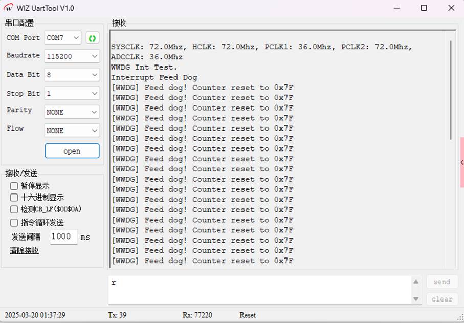
The main function of this program is to configure serial port communication, output the system clock frequency information, enable the interrupt function of the window watchdog, and perform the watchdog feeding operation through the interrupt service function to prevent system reset.

If you want to verify whether this code is correctly executing the "feeding the dog" (i.e., resetting the WWDG counter), add serial port print statements in the WWDG_IRQHandler interrupt handling function. Output debugging information each time the interrupt is triggered.
Modify the code:
void WWDG_IRQHandler(void)Then check the serial port print data, and you will see that "feed the dog" is currently being executed.
5 WWDG_Reset
5.1 Code Analysis
1.Header files and global variables
#include <stdlib.h>It includes standard libraries and custom header files.
USART_TEST is a pointer to USART1, used for subsequent serial port operations.
2. Function Declaration
void UART_Configuration(uint32_t bound);The UART_Configuration() function is used to configure serial communication.
The GetCmd() function is used to receive data from the serial port.
3. The main() function
int main(void)Clock and peripheral initialization:
RCC_APB1PeriphClockCmd(RCC_APB1Periph_WWDG, ENABLE) enables the clock for the Window Watchdog (WWDG).
delay_init() initializes the delay function.
UART_Configuration(115200) configures the serial communication, with a baud rate of 115200.
RCC_GetClocksFreq(&clocks) obtains the system clock frequency information.
Serial output information:
Output the system clock frequency information and test prompt information through the printf() function.
Window watchdog configuration:
WWDG_SetPrescaler(WWDG_Prescaler_8) sets the prescaler of the Window Watchdog to 8.
WWDG_SetWindowValue(0x5F) sets the window value to 0x5F.
WWDG_Enable(0x7F) enables the Window Watchdog, with an initial count value of 0x7F.
Main loop: while (1); The program enters an infinite loop. Since the watchdog for the window has not been fed, after a certain period of time, the watchdog for the window will trigger a reset.
4. UART_Configuration() function
void UART_Configuration(uint32_t bound)Enable the clocks for USART1 and GPIOA.
Configure PA9 as a re-mapped push-pull output, serving as the serial port transmit pin; configure PA10 as an open-drain input, serving as the serial port receive pin.
Configure the parameters of the serial port such as baud rate, data bits, stop bits, parity check, etc.
Initialize the serial port and enable it.
5. GetCmd() Function
uint8_t GetCmd(void)Check if there is any data in the serial port receive buffer (check the USART_FLAG_RXNE flag bit).
If there is data, receive one byte of data from the serial port and return it.
6. SER_PutChar() and fputc() function
int SER_PutChar(int ch)The SER_PutChar() function is used to send a character via the serial port. It waits until the sending completion flag (USART_FLAG_TC) is set before sending the character.
The fputc() function is the underlying implementation of the printf() function. When a newline character \n is output, it first sends the carriage return character \r, and then sends the character.
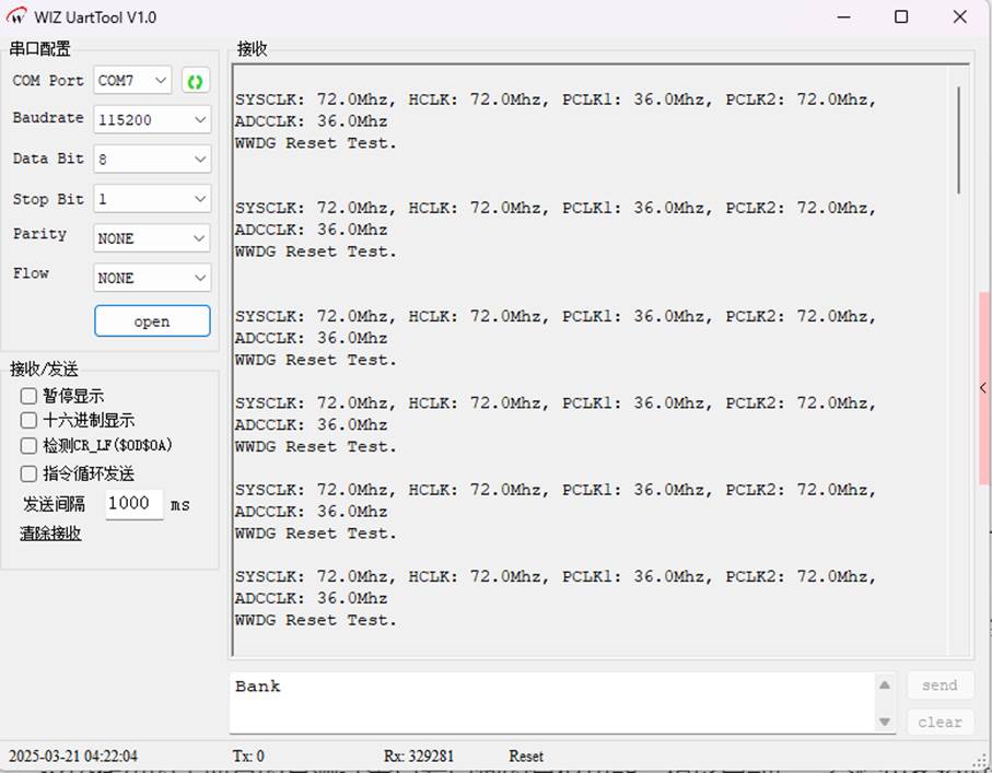
The main purpose of this code is to test the reset function of the window watchdog. After the program starts, it will output the system clock information and test prompt information, then configure and enable the window watchdog. Since there is no dog-feeding operation for the window watchdog in the main loop, the window watchdog will trigger a reset after a certain period of time, restarting the program. At the same time, the code also implements serial communication functionality, which is used to output information and receive data.
5.2 Download Verification
WIZnet is a fabless semiconductor company founded in 1998. Its products include the Internet processor iMCU™, which utilizes TOE (TCP/IP Offload Engine) technology and is based on a unique patented fully hardwired TCP/IP. The iMCU™ is designed for embedded Internet devices in various applications.
WIZnet has more than 70 distributors globally and has offices in Hong Kong, South Korea, and the United States, providing technical support and product marketing services.
The regions managed by the Hong Kong office include Australia, India, Turkey, and Asia (excluding South Korea and Japan).