
Chapter 23:W55MH32’s IWDG - Independent Watchdog
Chapter 23:W55MH32’s IWDG - Independent Watchdog
Chapter 23:W55MH32’s IWDG - Independent Watchdog
References for this chapter: "W55MH32 Reference Manual" - IWDG section.
When studying this chapter, it will be more effective to read it in conjunction with the IWDG section of the "W55MH32 Reference Manual", especially for the part related to register descriptions.
1 IWDG Introduction
The W55MH32 has two watchdogs. One is an independent watchdog and the other is a window watchdog. The independent watchdog is called a pet dog and the window watchdog is called a police dog. In this chapter, we mainly analyze the functional block diagram of the independent watchdog and its applications. The independent watchdog, in simpler terms, is a 12-bit decrementing counter. When the counter's value continuously decreases from a certain value to 0, the system will generate a reset signal, namely IWDG_RESET. If the counter value is refreshed before it reaches 0, no reset signal will be generated. This action is what we often refer to as feeding the dog. The watchdog function is powered by the VDD voltage domain and can still work in stop mode and standby mode.
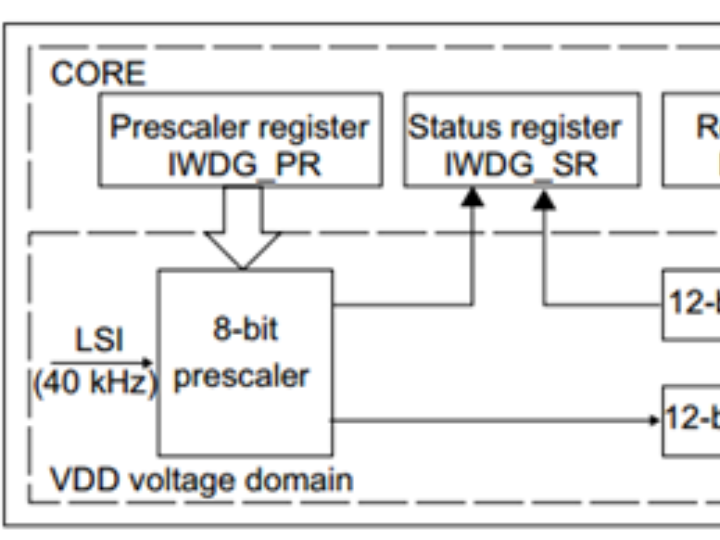
2 Analysis of the IWDG Function Block Diagram
The functional block diagram of IWDG is as follows:
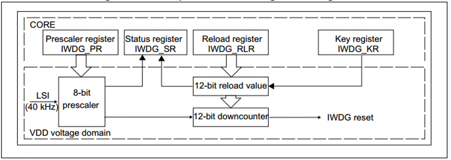
2.1 Independent Watchdog Timer
The clock of the independent watchdog is provided by an independent RC oscillator LSI. Even if the main clock fails, it remains effective and is highly independent. The frequency of the LSI is generally between 30 and 60 KHZ. There will be certain drift due to temperature and working conditions. We usually take 40 KHZ. Therefore, the timing period of the independent watchdog is not necessarily very precise and is only suitable for situations where the requirement for time accuracy is relatively low.
2.2 Counter Clockwork
The clock of the decrement counter is obtained by LSI through an 8-bit prescaler. We can set the prescaler register IWDG_PR to configure the division factor. The division factors can be: [4, 8, 16, 32, 64, 128, 256, 256]. The counter clock CK_CNT = 40 / 4 * 2^PRV, and the counter decrements by one for each counter clock cycle.
2.3 Counter
The counter of the independent watchdog is a 12-bit decrementing counter with a maximum value of 0XFFF. When the counter reaches 0, a reset signal, IWDG_RESET, will be generated, causing the program to restart its operation. If the counter value is refreshed before it reaches 0, no reset signal will be generated. The action of refreshing the counter value is commonly referred to as "feeding the dog".
2.4 Reload the registers
The reload register is a 12-bit register that holds the value to be written to the counter. The size of this value determines the overflow time of the independent watchdog. The timeout time Tout = (4 * 2^prv) / 40 * rlv (s), where prv is the value of the prescaler register and rlv is the value of the reload register.
2.5 Key register
The key register IWDG_KR can be regarded as a control register for the independent watchdog. There are mainly three control methods. Writing different values to this register will have different effects.
Key value | Key-value function |
0XAAAAA | Reload the value of RLR into CNT |
0X55555 | The PR and RLR registers can be written to. |
0XCCCC | Start IWDG |
By writing 0XCCC to the write key register to start the watchdog, this is a software-based startup method. Once the independent watchdog is activated, it cannot be turned off; only a reset can shut it down.
2.6 Status register
The status register SR has only bit 0: PVU and bit 1: RVU as valid. These two bits can only be operated by hardware, and cannot be manipulated by software. RVU: The watchdog counter reload value is updated. The hardware sets 1 to indicate that the reload value update is in progress, and the hardware clears 0 after the update is completed. PVU: The watchdog prescaler value is updated. The hardware sets '1' to indicate that the prescaler value update is in progress, and the hardware clears 0 after the update is completed. Therefore, the reload register/predivider register can only be updated when RVU/PVU equals 0.
3 IWDG Usage Instructions
An independent watchdog is generally used to detect and resolve faults caused by programs. For example, if a program runs normally for 50ms, and then immediately feeds the dog after completing this segment of the program, we set the timing overflow time of the independent watchdog to 60ms, which is a little more than the 50ms required for the program to be monitored. If the dog is not fed after more than 60ms, it indicates that the monitored program has malfunctioned and crashed. Then, a system reset will occur, causing the program to restart.
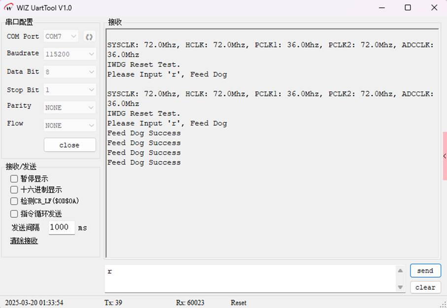
4 IWDG Reset Test Experiment
4.1 Code Analysis
It is mainly used to implement the watchdog timer (IWDG) reset test on the W55MH32 microcontroller, and to conduct data interaction via the serial port. Below, I will explain each part of the code in detail:
1. Header file inclusion
#include <stdlib.h>stdlib.h, string.h and stdio.h are header files of the standard C library, providing general tools, string processing and input/output functions respectively.
delay.h might be a custom header file used to implement the delay function.
w55mh32.h might be a header file related to a specific hardware (such as the W55MH32 chip).
2. Global variable definition
USART_TypeDef *USART_TEST = USART1;A pointer USART_TEST of type USART_TypeDef was defined and initialized to USART1, which means that subsequent serial port operations will use USART1.
3. Function Declaration
void UART_Configuration(uint32_t bound);The UART_Configuration() function is used to configure the serial port, and the parameter bound represents the baud rate.
The GetCmd() function is used to receive data from the serial port.
4. The main() function
int main(void)Initialization section:
delay_init() is the initialization delay function.
UART_Configuration(115200) configures the serial port at a baud rate of 115200.
RCC_GetClocksFreq(&clocks) obtains the system clock frequency information.
Print information:
Prints the system clock frequency information.
Prompts for a watchdog timer reset test and informs the user to input 'r' to feed the dog.
Watchdog timer configuration:
IWDG_WriteAccessCmd(IWDG_WriteAccess_Enable) enables write access to the watchdog timer.
IWDG_SetPrescaler(IWDG_Prescaler_64) sets the prescaler of the watchdog timer to 64.
IWDG_SetReload(0x7FF) sets the reload value of the watchdog timer to 0x7FF.
IWDG_ReloadCounter() reloads the counter of the watchdog timer.
IWDG_Enable() enables the watchdog timer.
Main loop:
Continuously calls the GetCmd() function to obtain serial port input.
If the input is 'r', calls IWDG_ReloadCounter() to feed the dog and prints "Feed Dog Success".
5. UART_Configuration() function
void UART_Configuration(uint32_t bound)Enable the clocks for USART1 and GPIOA.
Configure pin 9 of GPIOA as a re-mapped push-pull output for USART1's transmission; pin 10 as an open-drain input for USART1's reception.
Configure the parameters of USART1 such as baud rate, data bits, stop bits, parity check, etc.
Initialize USART1 and enable it.
6. GetCmd() Function
uint8_t GetCmd(void)Check the non-empty flag of the receive buffer of USART1, USART_FLAG_RXNE.
If the flag is set, it indicates that data has arrived. Receive the data from USART1 and return it.
7. SER_PutChar() Function
int SER_PutChar(int ch)Wait until the transmission completion flag USART_FLAG_TC of USART1 is set.
Send the character ch to USART1.
8. fputc() Function
int fputc(int c, FILE *f)Redirect the standard output function fputc() to send data through the serial port.
If the character to be sent is a newline character \n, then first send the carriage return character \r.
4.2 Download Verification
This code implements a simple watchdog timer reset test program. It communicates with the user via the serial port. The user can input "r" to feed the dog and prevent the watchdog timer from resetting due to timeout.
WIZnet is a fabless semiconductor company founded in 1998. Its products include the Internet processor iMCU™, which utilizes TOE (TCP/IP Offload Engine) technology and is based on a unique patented fully hardwired TCP/IP. The iMCU™ is designed for embedded Internet devices in various applications.
WIZnet has more than 70 distributors globally and has offices in Hong Kong, South Korea, and the United States, providing technical support and product marketing services.
The regions managed by the Hong Kong office include Australia, India, Turkey, and Asia (excluding South Korea and Japan).