
Chapter 20: W55MH32’s TIM - Basic Timer
Chapter 20: W55MH32’s TIM - Basic Timer
Chapter 20: W55MH32’s TIM - Basic Timer
Reference materials for this chapter: "W55H32 Reference Manual" - Basic Timer Section. When studying this chapter, it will be more effective to read along with the reference materials, especially for the sections related to register explanations.
1. Timer Classification
Timer | Counter resolution | Counter type | Pre-frequency division coefficient | Generate a DMA request | Capture / Comparison Channel | Complementary output |
TIM1、TIM8 | 16 bits | Up, down, up / Down | Any integer between 1 and 65536 | OK | 4 | Yes |
TIM2、TIM3、TIM4、TIM5 | 16 bits
| Up, down, up / Down | Any integer between 1 and 65536 | OK | 4 | No |
TIM9、TIM12 | 16 bits
| Upward | Any integer between 1 and 65536 | NO | 2 | No |
TIM10、TIM11、TIM13、TIM14 | 16 bits
| Upward | Any integer between 1 and 65536 | NO | 1 | No |
TIM6、TIM7 | 16 bits
| Upward | Any integer between 1 and 65536 | OK | 0 | No |
Advanced control timers (TIM1 and TIM8)
The two advanced control timers (TIM1 and TIM8) can be regarded as a three-phase PWM generator distributed across 6 channels, featuring complementary PWM outputs with dead zone insertion, and can also be considered as a complete general-purpose timer. The four independent channels can be used for:
● Input capture
● Output comparison
● Generate PWM (edge or center-aligned mode)
● Single pulse output
When configured as a 16-bit standard timer, it has the same functions as the TIMx timer. When configured as a 16-bit PWM generator, it has full modulation capability (0 - 100%).
In the debugging mode, the counter can be frozen, and the PWM output is disabled, thereby cutting off the switches controlled by these outputs. Many functions are the same as those of the standard TIM timer, and the internal structure is also the same. Therefore, the advanced control timer can work in coordination with the TIM timer through the timer link function, providing synchronous or event link functions.
General Timers (TIM2, TIM3, TIM4, TIM5)
In this series of products, there are 4 standard timers (TIM2, TIM3, TIM4, TIM5) built in, which can operate synchronously. Each timer has a 16-bit auto-load increment/decrement counter, a 16-bit prescaler, and 4 independent channels. Each channel can be used for input capture, output comparison, PWM and single pulse mode output. They can also work together with advanced control timers through the timer link function, providing synchronous or event linking functions. In the debugging mode, the counter can be frozen. Any of the standard timers can be used to generate PWM output. Each timer has an independent DMA request mechanism. These timers can also handle the signals of incremental encoders and the digital outputs of 1 to 3 Hall sensors.
General Timers (TIM10, TIM11, TIM9)
These timers are based on 16-bit auto-reload counters and 16-bit prescalers. TIM10 and TIM11 have an independent channel, while TIM9 has two independent channels for input capture/output comparison, PWM or single pulse mode. They can output these signals which can be synchronized with the full-featured general-purpose timers TIM2, TIM3, TIM4, and TIM5. They can also be used as simple time bases.
General timers (TIM13, TIM14, TIM12)
These timers are based on 16-bit auto-reload counters and 16-bit prescalers. TIM13 and TIM14 have an independent channel, while TIM12 has two independent channels for input capture/output comparison, PWM or independent channel output for single pulse mode. They can be synchronized with the full-function general-purpose timers TIM2, TIM3, TIM4, and TIM5. They can also be used as simple time bases. The independent watchdog has an independent watchdog based on a 12-bit decrement counter and an 8-bit prescaler, which is clocked by an internal independent 40kHz RC oscillator; since this RC oscillator is independent of the main clock, it can operate in stop and standby modes. It can be used as a watchdog to reset the entire system when an issue occurs, or as a free timer to provide timeout management for the application. The watchdog can be configured as software or hardware start-up through the option byte. In the debugging mode, the counter can be frozen.
Basic timers TIM6 and TIM7
These timers are mainly used for generating the DAC trigger. They can also be used as a general 16-bit timing base.
The window watchdog contains a 7-bit decrement counter that can be set to run freely. It can be used as a watchdog to reset the entire system in case of an issue. It is driven by the main clock and has an early warning interrupt function; in the debugging mode, the counter can be frozen.
System timing timer
This timer is specifically designed for real-time operating systems and can also be used as a standard decrement counter. It has the following features:
● 24-bit decrement counter
● Automatic reload function
● Can generate a maskable system interrupt when the counter reaches 0
● Programmable clock source
2 Explanation of the Basic Timer Function Block Diagram
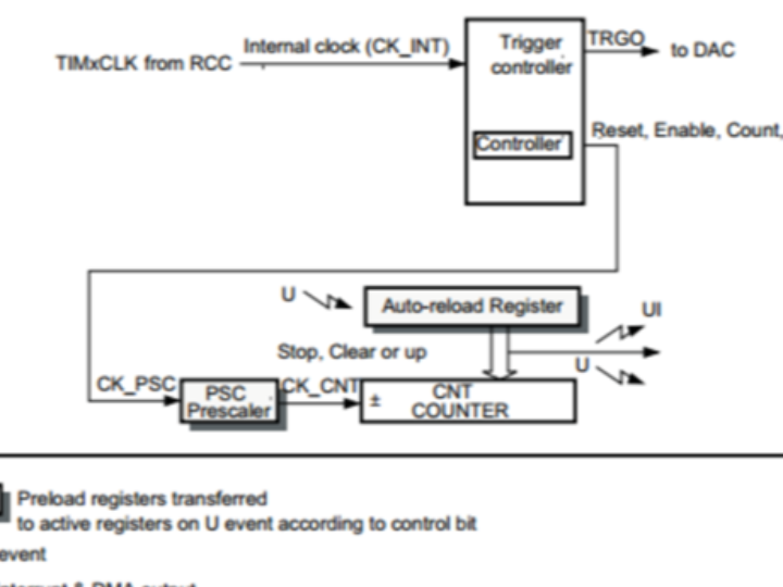
The core of the basic timer is the time base. Not only the basic timer has it, but also the general timer and the advanced timer do. When learning the timer, we start with the simple basic timer. When moving on to the learning of the general and advanced timers, we can directly skip the explanation of the time base part. The functional block diagram of the basic timer is shown below. Basic timer functional block diagram:
2.1 Clock source
The clock of the counter is provided by the internal clock (CK_INT).
The CEN bit in the TIMx_CR1 register and the UG bit in the TIMx_EGR register are the actual control bits (except that the UG bit is automatically cleared), and they can only be changed through software. Once the CEN bit is set to '1', the internal clock will provide a clock to the prescaler.
2.2 Counter clock
After the timer clock passes through the PSC prescaler, namely CK_CNT, it is used to drive the counter for counting. The PSC is a 16-bit prescaler that can divide the timer clock TIMxCLK by any number between 1 and 65536. The specific calculation method is: CK_CNT = TIMxCLK / (PSC + 1).
2.3 Counter
Counter CNT is a 16-bit counter that can only count upwards and its maximum count value is 65535. An update event is generated when the count reaches the auto-reload register, and the counter is reset to start counting from the beginning.
2.4 Automatic Reload of Registers
The automatic reloading register ARR is a 16-bit register, in which the maximum value that the counter can count to is stored. When the counter reaches this value and the interrupt is enabled, the timer will generate an overflow interrupt.
2.5 Calculation of the timing duration
The timing period of the timer is equal to the interrupt cycle of the counter multiplied by the number of interrupts. The counter is driven by CK_CNT, and the time for counting one number is the reciprocal of CK_CLK, which is equal to: 1/(TIMxCLK/(PSC + 1)). The time for generating one interrupt is equal to: 1/(CK_CLK * ARR). If a variable named "time" is set in the interrupt service routine to record the number of interrupts, then the required timing period can be calculated as: 1/CK_CLK * (ARR + 1) * time.
3. Detailed Explanation of Timer Initialization Structure
In the standard library function header file w55mh32_tim.h, four initialization structures for the timer peripheral are established. The basic timer only uses one of them, namely TIM_TimeBaseInitTypeDef. For details, please refer to the code listing: Basic Timer - 1. The other three will be explained in the advanced timer chapter.
Code Listing: Basic Timer - 1 Basic Timer Initialization Structure
typedef struct {TIM_Prescaler: Timer prescaler setting. The clock source through this prescaler becomes the timer clock. It sets the value of the TIMx_PSC register. The range that can be set is from 0 to 65535, achieving a frequency division of 1 to 65536.
TIM_CounterMode: Timer counting mode. It can be set to upward counting, downward counting, or three center-aligned modes. The basic timer can only be upward counting, that is, TIMx_CNT can only increment from 0 and does not require initialization.
TIM_Period: Timer period. It actually sets the value of the auto-reload register, which is updated to the shadow register when an event occurs. The range that can be set is from 0 to 65535.
TIM_ClockDivision: Clock division. It sets the division ratio of the timer clock CK_INT frequency to the sampling clock frequency of the digital filter. The basic timer does not have this function and does not need to be set.
TIM_RepetitionCounter: Repetition counter. It is a dedicated register bit for advanced control registers. By using it, the number of output PWMs can be easily controlled. Here, it does not need to be set.
Although the basic initialization structure of the timer has 5 members, for the basic timer, only two of them need to be set. Just think about using the basic timer, it is very simple.
WIZnet is a fabless semiconductor company founded in 1998. Its products include the Internet processor iMCU™, which utilizes TOE (TCP/IP Offload Engine) technology and is based on a unique patented fully hardwired TCP/IP. The iMCU™ is designed for embedded Internet devices in various applications.
WIZnet has more than 70 distributors globally and has offices in Hong Kong, South Korea, and the United States, providing technical support and product marketing services.
The regions managed by the Hong Kong office include Australia, India, Turkey, and Asia (excluding South Korea and Japan).