
Chapter 15: DMA in W55MH32
Chapter 15: DMA in W55MH32
Chapter 15: DMA in W55MH32
References for this chapter: "W55MH32 Chinese Reference Manual" - DMA Controller section.
When studying this chapter, it will be more effective to read it in conjunction with the DMA Controller section of "W55MH32 Chinese Reference Manual", especially for the part related to register explanations.
1 DMA Introduction
DMA (Direct Memory Access) - Direct Memory Access is an external device of a single-chip microcontroller. Its main function is to transfer data, but it does not require the CPU to be occupied. That is, when transferring data, the CPU can do other things, as if it were multi-threading. Data transmission supports from the peripheral device to the memory or from the memory to the memory. Here, the memory can be SRAM or FLASH. The DMA controller includes DMA1 and DMA2, where DMA1 has 7 channels and DMA2 has 5 channels. These channels can be understood as a kind of pipeline for data transmission. It should be noted that DMA2 is only present in large-capacity products and interconnection products.
2 DMA Function Block Diagram
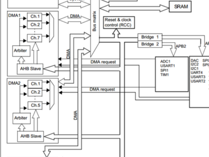
The DMA controller is independent of the kernel and belongs to a separate peripheral. Its structure is relatively simple. From a programming perspective, we only need to master the three parts in the functional block diagram. Please refer to the following figure. DMA block diagram: DMA controller block diagram:
2.1 DMA request
If an external device wants to transfer data through DMA, it must first send a DMA request to the DMA controller. After receiving the request signal, the controller will give the external device an acknowledgement signal. Once the external device responds and the DMA controller receives the acknowledgement signal, the DMA transmission will be initiated until it is completed.
There are two DMA controllers: DMA1 and DMA2. DMA1 has 7 channels, and DMA2 has 5 channels. The channels of different DMA controllers correspond to different external device requests, which determines how we should set it in software programming. Please refer to the DMA request mapping table for details:
Peripheral equipment | Channel 1 | Channel 2 | Channel 3 | Channel 4 | Channel 5 | Channel 6 | Channel 7 |
ADC1 | ADC1 |
|
|
|
|
|
|
SPI/I²S |
| SPI1_RX | SPI1_TX | SPI/I2S2_RX | SPI/I2S2_TX |
|
|
USART | USART3_TX | USART3_RX |
| USART1_TX | USART1_RX | USART2_RX | USART2_TX |
I²C |
|
|
| I2C2_TX | I2C2_RX | I2C1_TX | I2C1_RX |
TIM1 | TIM1_CH1 | TIM1_CH2 | TIM1_TX4 TIM1_TRIG TIM1_COM | TIM1_UP | TIM1_CH3 |
|
|
TIM2 | TIM2_CH3 | TIM2_UP |
|
| TIM2_CH1 |
| TIM2_CH2 TIM2_CH4 |
TIM3 |
| TIM3_CH3 | TIM3_CH4 TIM3_UP |
|
| TIM3_CH1 TIM3_TRIG |
|
TIM4 | TIM4_CH1 |
|
| TIM4_CH2 | TIM4_CH3 |
| TIM4_UP |
Peripheral equipment | Channel 1 | Channel 2 | Channel 3 | Channel 4 | Channel 5 |
ADC3⁽¹⁾ |
|
|
|
| ADC3 |
SPI/I²S3 | SPI/I²S3_RX | SPI/I²S3_TX |
|
|
|
UART4 |
|
| UART4_RX |
| UART4_TX |
SDIO⁽¹⁾ |
|
|
| SDIO |
|
TIM5 | TIM5_CH4 TIM5_TRIG | TIM5_CH3 TIM5_UP |
| TIM5_CH2 | TIM5_CH1 |
TIM6/DAC Channel 1 |
|
| TIM6_UP/ DAC Channel 1 |
|
|
TIM7/DAC Channel 2 |
|
|
| TIM7_UP/ DACChannel 2 |
|
TIM8⁽¹⁾ | TIM8_CH3 TIM8_UP | TIM8_CH4 TIM8_TRIG TIM8_COM | TIM8_CH1 |
| TIM8_CH2 |
Among them, the DMA requests for ADC3, SDIO and TIM8 only exist in high-capacity products. This point should be noted in specific projects.
2.2 Passage
DMA has 12 independent and programmable channels. Among them, DMA1 has 7 channels and DMA2 has 5 channels. Each channel corresponds to the DMA request of different peripherals. Although each channel can receive requests from multiple peripherals, only one can be received at a time, and multiple cannot be received simultaneously.
2.3 Arbiter
When multiple DMA channel requests occur, it indicates a problem of the sequence of response processing, which is also managed by the arbiter. The arbiter manages DMA channel requests in two stages. The first stage is the software stage, which can be set in the DMA_CCRx register, with four levels of priority: very high, high, medium, and low. The second stage is the hardware stage. If the priorities of two or more DMA channel requests are the same, their priorities depend on the channel number. The lower the number, the higher the priority. For example, channel 0 has a higher priority than channel 1. In large-capacity products and interconnection products, the DMA1 controller has a higher priority than the DMA2 controller.
3 DMA data configuration
With DMA, the core aspect lies in configuring the data to be transferred, including where the data comes from, where it is to go, what the unit of the data is, how much data to transfer, whether it is a single transmission or a cyclic transmission, and so on.
3.1 DMA transmission direction
We know that there are three directions for DMA to transfer data: from peripheral to memory, from memory to peripheral, and from memory to memory. The specific direction is configured by the DMA_CCR bit 4 DIR: 0 indicates from peripheral to memory, and 1 indicates from memory to peripheral. The peripheral addresses involved are configured by DMA_CPAR, and the memory addresses are configured by DMA_CMAR.
Peripheral devices to memory
When we perform data transfer from the peripheral to the memory, taking ADC acquisition as an example. The address of the DMA peripheral register corresponds to the address of the ADC data register, and the address of the DMA memory is the address of the variable we have defined (used to receive and store the data collected by ADC). We set the direction of the peripheral as the source address.
Memory to peripheral device
When we transfer data from the memory to the peripheral devices, taking the serial port sending data to the computer as an example. The address of the DMA peripheral register corresponds to the address of the serial port data register. The address of the DMA memory is the address of the variable we have defined (equivalent to a buffer, used to store the data sent to the computer through the serial port). We set the direction to the target address.
Memory to memory
When we perform data transfer from one memory to another, taking the example of copying data from internal FLASH to internal SRAM. The address of the DMA peripheral register corresponds to the address of the internal FLASH (here we regard the internal FLASH as a peripheral device), and the address of the DMA memory is the address of the custom variable (equivalent to a buffer used to store data from the internal FLASH). We set the peripheral (i.e., the internal FLASH) as the source address. Different from the above two, here we need to configure the bit 14:MEM2MEM of DMA_CCR to 1 for the memory-to-memory mode, and start the M2M mode.
3.2 Transmission size and unit
After we have configured where the data should come from and where it should go, we also need to know how much data we are going to transmit and what the unit of the data is.
Take sending data to a computer via a serial port as an example. We can send a large amount of data to the computer at once, and the specific amount depends on the configuration of DMA_CNDTR, which is a 32-bit register. It can transfer a maximum of 65,535 data at a time.
For the data transmission to be correct, the data width stored in the source and destination addresses must also be consistent. The serial port data register is 8 bits, so the data we define to be sent must also be 8 bits. The data width of the peripheral device is configured by DMA_CCRx's PSIZE[1:0], which can be 8/16/32 bits. The data width of the memory is configured by DMA_CCRx's MSIZE[1:0], which can be 8/16/32 bits.
Under the control of the DMA controller, for the data to be transferred orderly from one place to another, the increment mode of the data pointers on both sides must also be set correctly. The address pointer of the peripheral device is configured by DMA_CCRx's PINC, and the address pointer of the memory is configured by MINC. Taking the sending of data to a computer via the serial port as an example, there is a large amount of data to be sent. After each transmission is completed, the memory address pointer should be incremented by 1, while the serial port data register has only one, so the address pointer of the peripheral device remains unchanged. The specific increment mode of the data pointer is determined by the actual situation.
3.3 Transmission completion time
When the data transmission is completed, we can identify it by querying the flag bits or through interrupts. Each DMA channel has corresponding flag bits when the DMA transmission is half completed, completed, or has an error. If the corresponding type of interrupt is enabled, an interrupt will be generated. For detailed descriptions of each flag bit, please refer to the detailed description of the DMA Interrupt Status Register DMA_ISR.
The transmission completion also has two modes: one-time transmission or loop transmission. One-time transmission is quite straightforward; it stops after one transmission and cannot be resumed until the DMA enable is disabled and reconfigured. Loop transmission, on the other hand, resumes the configuration of the first transmission after each transmission is completed and repeats continuously. The specific control is by the CIRC loop mode bit in the DMA_CCRx register.
4 Detailed Explanation of the DMA Initialization Structure
The standard library functions create an initialization structure xxx_InitTypeDef (where xxx represents the name of the peripheral) for each peripheral. The members of this structure are used to set the working parameters of the peripheral, and the standard library function xxx_Init() calls these settings to enter the corresponding registers of the peripheral, achieving the purpose of configuring the working environment of the peripheral.
The combination of the structure xxx_InitTypeDef and the library function xxx_Init is the essence of the standard library. Understanding the meaning of each member of the structure xxx_InitTypeDef basically enables one to handle the peripheral with ease. The structure xxx_InitTypeDef is defined in the file W55MH32_xxx.h (where xxx is the name of the peripheral), and the library function xxx_Init is defined in the file W55MH32_xxx.c. During programming, we can use these two files along with their comments.
DMA_InitTypeDef - Initialization structure
1. typedef struct
1) DMA_PeripheralBaseAddr: Peripheral address, sets the value of the DMA_CPAR register; usually set to the data register address of the peripheral, or to one of the memory addresses if it is a memory-to-memory mode.
2) DMA_Memory0BaseAddr: Memory address, sets the value of the DMA_CMAR register; usually set to the starting address of our custom memory area.
3) DMA_DIR: Transfer direction selection, can be peripheral to memory or memory to peripheral. It sets the value of the DIR[1:0] bits in the DMA_CCR register. There is no memory-to-memory direction selection here. When using memory-to-memory, just use one of the memories as the peripheral.
4) DMA_BufferSize: Sets the number of data to be transferred, initializes the value of the DMA_CNDTR register.
5) DMA_PeripheralInc: If configured as DMA_PeripheralInc_Enable, enables the automatic increment function of the peripheral address. It sets the value of the PINC bit in the DMA_CCR register; usually, peripherals have only one data register, so this bit is generally not enabled.
6) DMA_MemoryInc: If configured as DMA_MemoryInc_Enable, enables the automatic increment function of the memory address. It sets the value of the MINC bit in the DMA_CCR register; our custom memory areas usually store multiple data, so the automatic increment function of the memory address should be enabled.
7) DMA_PeripheralDataSize: Peripheral data width, can be byte (8 bits), half word (16 bits), or word (32 bits), it sets the value of the PSIZE[1:0] bits in the DMA_CCR register.
8) DMA_MemoryDataSize: Memory data width, can be byte (8 bits), half word (16 bits), or word (32 bits), it sets the value of the MSIZE[1:0] bits in the DMA_CCR register. The data widths of both sides should be set to the same size when transferring data between the peripheral and the memory.
9) DMA_Mode: DMA transfer mode selection, can be single transfer or circular transfer, it sets the value of the CIRC bit in the DMA_CCR register. In our example, the ADC acquisition is continuously and cyclically performed, so the circular transfer mode is used.
10) DMA_Priority: Software sets the priority of the channel, there are 4 selectable priorities, namely very high, high, medium, and low, it sets the value of the PL[1:0] bits in the DMA_CCR register. The priority of the DMA channel is meaningful only when multiple DMA channels are used simultaneously. If it is a single channel, the priority can be set arbitrarily.
DMA_M2M: Memory-to-memory mode, used when using memory-to-memory, sets the bit 14 MEN2MEN in the DMA_CCR to start the memory-to-memory mode.
5 DMA Memory to Peripheral Mode Experiment
5.1 Code analysis
USART initialization
Code Listing: DMA-5 USART Initialization
1. void UART_Configuration(uint32_t bound)
This code defines the UART_Configuration function which is used to configure the UART. It receives the baud rate as a parameter. The function first initializes the GPIO and USART configuration structures, then enables the clocks for USART1 and GPIOA. Next, PA9 is configured as a re-mapped push-pull output for the TX pin, and PA10 is configured as an open-drain input for the RX pin. Afterwards, the parameters such as baud rate, data bits, stop bits, parity bits, and hardware flow control are set for the USART, and the receive and transmit modes are enabled. Finally, the USART is initialized and enabled.
Serial port DMA transmission configuration
Code Listing: DMA-6 USART1 Sending Request DMA Settings
1. void DMA_RecvConfiguration(void)
The code defines two functions for configuring the receiving and sending functions of DMA (Direct Memory Access). The DMA_RecvConfiguration function configures the DMA receiving function of USART1, enables the clock of DMA1, initializes DMA1 channel 5 to receive data from the data register of USART1 to the memory buffer Buff, and sets parameters such as data direction, buffer size, data increment mode, data size, working mode, and priority. Finally, it enables this channel. The DMA_SendConfiguration function configures the DMA sending function of USART1, also enabling the clock of DMA1, initializing DMA1 channel 4 to send data from the memory buffer Buff to the data register of USART1, and setting similar parameters before enabling this channel.
Main function
Code Listing: Main Function of DMA-7 Memory-to-Peripheral Mode
1. int main(void)This code is a main function in C language, mainly implementing the asynchronous DMA (Direct Memory Access) test function for USART (Universal Synchronous/Asynchronous Receiver/Transmitter). The specific steps are as follows:
1. Define variables i and clocks. i is used for loop counting, and clocks is used to store the clock frequency information.
2. Initialize the delay function, configure UART with a baud rate of 115200, obtain the system clock frequency and store it in clocks.
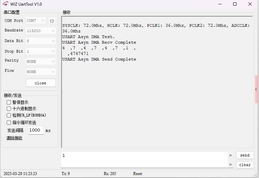
3. Print the frequency information of all system clocks, including SYSCLK, HCLK, PCLK1, PCLK2, and ADCCLK, and output the test prompt information.
4. Enter an infinite loop. In the loop, alternate between receiving and sending operations:
Receiving operation: First disable DMA1 channel 4, enable the receiving DMA request of USART1, call the DMA_RecvConfiguration function to configure DMA reception, wait for the receiving completion flag to be set, print the completion information and output the received data one by one.
Sending operation: Disable DMA1 channel 5, enable the sending DMA request of USART1, call the DMA_SendConfiguration function to configure DMA transmission, wait for the sending completion flag to be set, print the completion information.
In this way, the data receiving and sending tests are continuously carried out.
5.2 Download verification
Ensure that the hardware connections of the development board are correct. On the computer, open the Serial Port Debugging Assistant and download the compiled program to the development board.
WIZnet is a fabless semiconductor company founded in 1998. Its products include the Internet processor iMCU™, which utilizes TOE (TCP/IP Offload Engine) technology and is based on a unique patented fully hardwired TCP/IP. The iMCU™ is designed for embedded Internet devices in various applications.
WIZnet has more than 70 distributors globally and has offices in Hong Kong, South Korea, and the United States, providing technical support and product marketing services.
The regions managed by the Hong Kong office include Australia, India, Turkey, and Asia (excluding South Korea and Japan).