
Chapter 13: Basic Concepts of Communication for W55MH32
Chapter 13: Basic Concepts of Communication for W55MH32
Chapter 13: Basic Concepts of Communication for W55MH32
Data transmission is often required between computer devices or between integrated circuits. In the subsequent chapters of this book, we will learn about various communication methods. Therefore, in this chapter, we will first introduce the basic concepts of these communications in a unified manner.
1 Serial communication and parallel communication
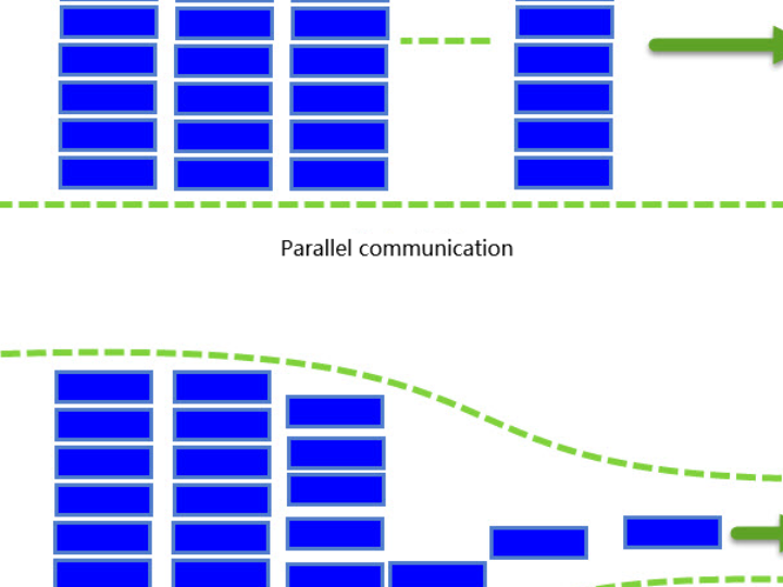
According to the mode of data transmission, communication can be divided into serial communication and parallel communication. Serial communication refers to the communication method where devices transmit data bit by bit through a small number of data signal lines (generally less than 8), ground lines, and control signal lines. Parallel communication generally refers to the communication method that uses 8, 16, 32, and 64 or more data lines for transmission. The comparison of their communication transmission is shown in the following figure. The comparison chart of parallel communication and serial communication. Parallel communication is like a multi-lane highway, which can simultaneously transmit multiple data bits of data, while serial communication is like a single-lane highway, where only one data bit of data can be transmitted at the same time.
Obviously, since a single data transmission can carry multiple data bits, under the same data transmission rate, the amount of data transmitted by parallel communication is much larger. While serial communication can save the hardware cost of data lines (especially at long distances) as well as the wiring area of the PCB. The comparison of the characteristics between serial communication and parallel communication is shown in the following table: Characteristics Comparison of Serial Communication and Parallel Communication
Characteristics | Serial communication | Parallel communication |
Communication distance | Far away | Recently |
Anti-interference capability | Stronger | Weaker |
Transmission rate | Slower | Higher |
Cost | Lower | Higher |
However, since parallel transmission has high requirements for synchronization, and as communication rates increase, the problem of signal interference will significantly affect communication performance. Now, with the development of technology, more and more application scenarios are adopting high-speed serial differential transmission.
2 Full-duplex, half-duplex and simplex communication
According to the direction of data communication, communication can be divided into full-duplex, half-duplex and simplex communication. They are mainly distinguished by the direction of the channel. As shown in the figure below, full-duplex - half-duplex and simplex communication, and the following table. Communication method description:
Communication method | Explanation |
Full Duplex | At the same time, data can be transmitted and received simultaneously between the two devices. |
Half-duplex | Data can be transmitted and received between the two devices, but they cannot do so simultaneously. |
Simplex | At any given time, only one direction of communication can be carried out, that is, one is fixed as the transmitting device, and the other is fixed as the receiving device. |
Let's use the highway as an analogy. Full-duplex communication is like a two-way lane where the traffic in both directions is independent of each other. Half-duplex is like a country road where only one vehicle can pass at a time, and vehicles coming from the opposite direction can only wait until the road becomes clear before passing. And single-duplex is like a one-way street where vehicles from the other direction are completely prohibited from passing.
3 Synchronous communication and asynchronous communication
Based on the data synchronization method of communication, it can be divided into synchronous and asynchronous types. It can be simply distinguished according to whether a clock signal is used during the communication process.
In synchronous communication, both the transmitting and receiving devices will use a single signal line to represent the clock signal. Under the drive of the clock signal, both sides coordinate and synchronize the data. See the figure below for synchronous communication. In communication, both sides usually uniformly stipulate to sample the data line at the rising edge or falling edge of the clock signal:
In asynchronous communication, no clock signal is used for data synchronization. Instead, some synchronization signals are interspersed directly within the data signal, or the main data is packaged and transmitted in the form of data frames. See the figure below. For certain asynchronous communication, in some communications, both parties need to agree on the data transmission rate in order to achieve better synchronization.
In synchronous communication, the majority of the content transmitted by the data signal is valid data. In asynchronous communication, various identifiers of frames are included. Therefore, synchronous communication is more efficient, but the allowable clock error for both parties in synchronous communication is smaller, while the allowable clock error for both parties in asynchronous communication is larger.
4 Data transmission rate
One of the very important parameters for measuring communication performance is the communication rate, usually expressed in bit rate (Bitrate), which is the number of binary bits transmitted per second, measured in bits per second (bit/s). A concept that is easily confused with bit rate is "baud rate" (Baudrate), which indicates the number of symbols transmitted per second. A symbol is the concept of modulation of communication signals. In communication, time intervals of the same length are used to represent a binary digit, and such signals are called symbols. For example, in common communication transmission, 0V represents the digit 0 and 5V represents the digit 1. Then, one symbol can represent two states, 0 and 1, so one symbol is equal to one binary bit. At this time, the baud rate is the same as the bit rate; if in communication transmission, 0V, 2V, 4V, and 6V respectively represent the binary numbers 00, 01, 10, and 11, then each symbol can represent four states, that is, two binary bit positions. Therefore, the number of symbols is half of the number of binary bit positions, and at this time, the baud rate is half of the bit rate. Because in many common communications, one symbol represents two states, people often directly use the baud rate to represent the bit rate. Although this is not incorrect in a strict sense, I hope you can understand the difference between them.
WIZnet is a fabless semiconductor company founded in 1998. Its products include the Internet processor iMCU™, which utilizes TOE (TCP/IP Offload Engine) technology and is based on a unique patented fully hardwired TCP/IP. The iMCU™ is designed for embedded Internet devices in various applications.
WIZnet has more than 70 distributors globally and has offices in Hong Kong, South Korea, and the United States, providing technical support and product marketing services.
The regions managed by the Hong Kong office include Australia, India, Turkey, and Asia (excluding South Korea and Japan).