
Chapter 12: W55MH32’s SysTick - System Timer
Chapter 12: W55MH32’s SysTick - System Timer
Chapter 12: W55MH32’s SysTick - System Timer
The reference materials for this chapter are "Cortex-M3 Core Programming Manual" - Chapter 4.5 "SysTick Timer (STK)" and Chapter 4.48 "SHPRx". In the STK chapter, there is an introduction to SysTick and detailed descriptions of the registers. Since SysTick is an external peripheral of the CM3 core, the definitions of the registers and some library functions are implemented in the header file core_CM3.h. Therefore, when learning about SysTick, you can refer to these two materials, one being the documentation and the other being the source code.
1 SysTick Introduction
SysTick - The System Timer is an external device within the CM3 core, embedded in the NVIC. The System Timer is a 24-bit decrementing counter. Each time the counter counts up, the duration is 1/SYSCLK. Typically, we set the system clock SYSCLK to 72M. When the value in the reload register decrements to 0, the System Timer generates an interrupt, and this cycle repeats.
Since SysTick is an external device of the CM3 core, all single-chip microcontrollers based on the CM3 core have this System Timer, making it easy for software to be ported in CM3 microcontrollers. The System Timer is generally used in operating systems to generate time bases and maintain the heartbeat of the operating system.
2 Introduction to the SysTick Register
SysTick - The system timer has four registers. A brief introduction is as follows. When using SysTick to generate timing, only the first three registers need to be configured, and the last calibration register does not need to be used.
Register name | Register description |
CTRL | SysTick Control and Status Register |
LOAD | SysTick reloads the value register |
VAL | SysTick Current Value Register |
CALIB | SysTick calibration value register |
Section | Name | Type | Reset value | Description |
16 | COUNTFLAG | R/W | 0 | If after the last reading of this register, SysTick has reached 0, then this bit will be 1. |
2 | CLKSOURCE | R/W | 0 | Clock source selection bit: 0 = AHB/8, 1 = Processor clock AHB |
1 | TICKINT | R/W | 0 | 1 = When SysTick counts down to 0, a SysTick exception request is generated. 0 = No action occurs when it reaches 0. The counter can be determined to have decremented to 0 by reading the COUNTFLAG flag bit. |
0 | ENABLE | R/W | 0 | The enable bit of the SysTick timer |
Section | Name | Type | Reset value
| Description |
23:0 | RELOAD | R/W | 0 | When the countdown reaches zero, the reloaded value will be... |
Section | Name
| Type
| Reset value
| Description |
23:0 | CURRENT | R/W | 0 | When reading, it returns the current countdown value. When writing, it sets it to zero and also clears the COUNTFLAG flag in the SysTick control and status register. |
Section | Name
| Type
| Reset value
| Description |
31 | NOREF | R | 0 | NOREF flag. Reads as zero. Indicates that a separate reference clock is provided. The frequency of this clock is HCLK/8 |
30 | SKEW | R | 1 | Reads as one. Calibration value for the 1 ms inexact timing is not known because TENMS is not known. This can affect the suitability of SysTick as a software real time clock |
23:0 | TENMS | R | 0 | Indicates the calibration value when the SysTick counter runs on HCLK max/8 as external clock. The value is product dependent, refer to the Product Reference Manual, SysTick Calibration Value section. When HCLK is at max frequency, SysTick period is 1ms. If calibration info unknown, calculate from processor/external clock frequency. |
The calibration value register of the system timer is not needed in the timing experiment. The descriptions of each bit are taken from the English version in the manual, which is rather obscure and difficult to understand. For now, we don't know what this register is used for. Those who have studied it can share their insights, serving as a starting point for discussion.
3 Introduction to SysTick Timer
3.1 Code analysis
SysTick is a peripheral of the kernel. The definitions of related registers and the library functions are all contained in the kernel-related library file core_cm3.h.
SysTick Configuration Library Function
Code Listing: SysTick-1 SysTick Configuration Library Function
__STATIC_INLINE uint32_t SysTick_Config(uint32_t ticks)When programming with the firmware library, we only need to call the library function SysTick_Config(). The parameter "ticks" is used to set the value of the reload register. The maximum value cannot exceed the value of the reload register's 224. When the value of the reload register decreases to 0, an interrupt is generated, and then the value of the reload register is reloaded and the count continues to decrease. This process repeats in a cycle. Immediately after that, the interrupt priority is set. Finally, the clock of the system timer is configured to be equal to AHBCLK = 72M, enabling the timer and timer interrupts. Thus, the system timer is configured, and this is accomplished with just one library function.
The SysTick_Config() library function mainly configures the three registers in SysTick: LOAD, VAL, and CTRL. For the specific details, please refer to the code comments.
Configure the priority of the SysTick interrupt
The SysTick_Config() library function also calls the firmware library function NVIC_SetPriority() to configure the interrupt priority of the system timer. This library function is also defined in core_m3.h, and its prototype is as follows:
__STATIC_INLINE void NVIC_SetPriority(IRQn_Type IRQn, uint32_t priority)The function first checks the size of the formal parameter IRQn. If it is less than 0, it indicates that this is a system exception. The priority of the system exception is controlled by the register SHPRx in the kernel peripheral SCB. If it is greater than 0, it is an external interrupt. The priority of the external interrupt is controlled by the IPx register in the kernel peripheral NVIC.
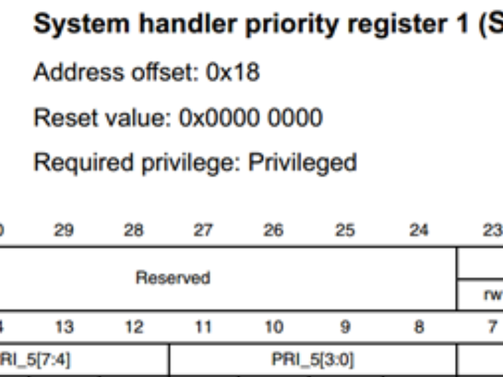
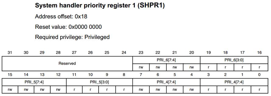
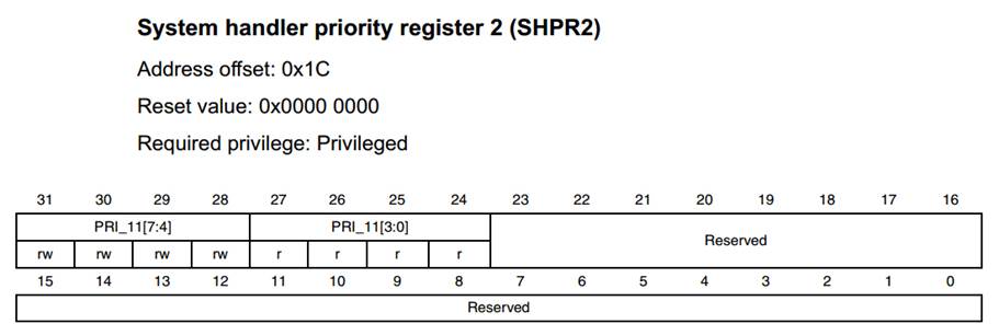
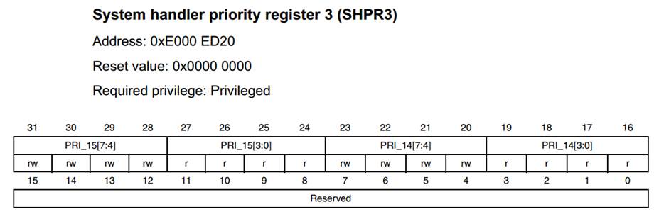
Because SysTick belongs to the kernel peripheral, it is a little different from the interrupt priority of normal peripheral, and there is no preemptive priority and sub-priority. In W55MH32, the interrupt priority of the kernel peripheral is configured by the register of the kernel SCB peripheral: SHPRx (x=1.2.3). A detailed description of the SHPRx register can be found in the Cortex-M3 Kernel Programming Manual, section 4.4.8. We briefly describe this register below.
SPRH1-SPRH3 is a 32-bit register, but it can only be accessed in bytes. Every 8 fields control the configuration of the interrupt priority of one kernel peripheral. In W55MH32, only the high four bits (7:4) are valid, and the low four bits are not used. Therefore, the interrupt priority of the kernel peripheral can be programmed as: 0 to 15, with only 16 programmable priorities. The smaller the value, the higher the priority. If the software priority configuration is the same, the priority level is determined by the position number in the interrupt vector table, and the smaller the number, the higher the priority.
Exception | Field | Register description |
Memory management fault | PRI_4 | SHPR1 |
Bus fault | PRI_5 | SHPR1 |
Usage fault | PRI_6 | SHPR1 |
SVCall | PRI_11 | SHPR2 |
PendSV | PRI_14 | SHPR3 |
SysTick | PRI_15 | SHPR3 |
If you want to modify the priority of the kernel peripherals, you only need to modify a certain field of the following three registers:
In the system timer, the priority is configured as (1UL << __NVIC_PRIO_BITS) - 1UL), where the macro __NVIC_PRIO_BITS is 4. The calculation result is 15. It can be seen that the priority set for the system timer at this time is the lowest among the kernel peripherals. If you want to modify the priority, you can simply change this value. The range is from 0 to 15.
NVIC_SetPriority (SysTick_IRQn, (1UL << __NVIC_PRIO_BITS) - 1UL);However, here comes the problem. Just now, we only learned about the priority configuration of the peripherals in the kernel. What if I use both the systick and the on-chip peripherals at the same time? And the on-chip peripherals also need to use interrupts. Then how should we set the interrupt priority of the systick and that of the peripherals? Could it be that since the systick is a peripheral within the kernel, its interrupt priority must be higher than that of the peripherals outside the kernel?
From the chapter "Overview of Interrupt Applications for W55MH32", we know that when setting the interrupt priority of peripherals, they should first be grouped, and then the priority and sub-priority should be set. While for kernel peripherals like the systick, when configuring, only one register needs to be configured, and the value range is from 0 to 15. Since the configuration methods are different, how can we distinguish the priorities of the two? Let's illustrate with an example.
For example, a peripheral is configured with interrupt priority grouping of 2, preemption priority of 1, sub-priority of 1, and systick's priority of 15, which is the default configuration of the firmware library. When comparing the interrupt priorities of a kernel peripheral and an on-chip peripheral, we just need to catch that NVIC's interrupt priority grouping is valid not only for the on-chip peripheral, but also for the kernel's. We convert systick's priority 15 into a binary value of 1111(0b). We convert systick's priority 15 to a binary value of 1111(0b), and because NVIC's priority grouping 2, then the first two 11(0b) is 3, the last two 11(0b) is also 3. Both preemptive and sub-priority is lower than that of the peripheral we set. If when both are configured with the same software priority, then compare their hardware numbers in the interrupt vector table; the smaller the number, the higher the priority.
SysTick initialization function
Code Listing: SysTick-2 SysTick Initialization Function
void SysTick_Init(void)The SysTick initialization function is written by the user. It calls the SysTick_Config() function from the firmware library. By setting the parameters of this function, it determines how many times the system timer will generate an interrupt after a certain period of time.
Calculation of SysTick interrupt time
The counter of the SysTick timer is a decrementing counter. The time TDEC for one count is 1/CLKAHB. When the value in the reload register VALUELOAD reaches 0, an interrupt is generated. It can be known that the time TINT for one interrupt is VALUELOAD * TDEC = VALUELOAD/CLKAHB. Here, CLKAHB = 72 MHz. If VALUELOAD is set to 72, the time TINT for one interrupt is 72/72M = 1us. However, a 1us interrupt is of little significance. The entire program's focus is on entering and exiting the interrupt, and there is simply no time to handle other tasks.
The parameter of SysTick_Config() is configured as SystemCoreClock / 100000 = 72M / 100000 = 720. From the analysis just now, we know that the value of this parameter is ultimately written to the reload register LOAD. Therefore, we can know that the time TINT for the SysTick timer interrupt to occur once is 720 / 72M = 10us.
Calculation of SysTick timing duration
After setting the interrupt duration TINT, we can set a variable t to record the number of interrupts. Then, multiplying this variable t by the interrupt duration TINT can calculate the required timing duration.
SysTick timing function
After setting the interrupt time TINT, we can set a variable t to record the number of times the interrupt occurs. Then, multiplying this variable t by the interrupt time TINT can calculate the required timing duration.
SysTick timing function
Now we define a microsecond-level delay function, with the parameter nTime. When this parameter is multiplied by the interrupt time TINT, the desired delay time can be obtained. Here, TINT has been set to 10us. For the specific invocation of this function, please refer to the comments.
void Delay_us(__IO u32 nTime)In the function Delay_us(), we wait until TimingDelay reaches 0. When TimingDelay becomes 0, it indicates that the delay time has elapsed. The variable TimingDelay decreases in the interrupt function. That is, every time the SysTick triggers an interrupt, TimingDelay decreases by 10 microseconds.
SysTick interrupt service function
void SysTick_Handler(void)The interrupt reset function calls another function, TimingDelay_Decrement(), whose prototype is as follows:
void TimingDelay_Decrement(void)The value of TimingDelay is equal to the value of nTime passed into the delay function. For example, if nTime = 100000, the delay time is equal to 100000 * 10us = 1s.
We know that when the counter of systick decreases from the reload value to 0, the bit 16:countflag in the CTRL register will be set to 1, and reading the value of this bit can clear it to 0. Therefore, we can implement the delay using the software query method. The specific code can be found in Code List: SysTick-3 and Code List: SysTick-4. I'm sure that this writing style will be more preferred by beginners because it is direct and has a simple pattern.
Code Listing: SysTick-3 Systick Microsecond-level Delay
void SysTick_Delay_Us( __IO uint32_t us)Code Listing: SysTick-4 systick Microsecond-level Delay
void SysTick_Delay_Ms( __IO uint32_t ms)In these delay functions at the microsecond and millisecond levels, we still called the firmware library function SysTick_Config. The detailed description of this function can be found in the code listing: SysTick-5. The accompanying code comments should be sufficient for understanding. Among them, SystemCoreClock is a macro with a size of 72,000,000. If you don't want to use this macro, you can directly change it to a number.
Code Listing: SysTick-5 systick configuration function
static __INLINE uint32_t SysTick_Config(uint32_t ticks)WIZnet is a fabless semiconductor company founded in 1998. Its products include the Internet processor iMCU™, which utilizes TOE (TCP/IP Offload Engine) technology and is based on a unique patented fully hardwired TCP/IP. The iMCU™ is designed for embedded Internet devices in various applications.
WIZnet has more than 70 distributors globally and has offices in Hong Kong, South Korea, and the United States, providing technical support and product marketing services.
The regions managed by the Hong Kong office include Australia, India, Turkey, and Asia (excluding South Korea and Japan).