
Chapter 11: W55MH32’s EXTI - External Interrupt/Event Controller
Chapter 11: W55MH32’s EXTI - External Interrupt/Event Controller
Chapter 11: W55MH32’s EXTI - External Interrupt/Event Controller
Reference materials for this chapter: "W55MH32 - Chinese Reference Manual" - the Interrupt and Event Chapter and Chapter 7.4 - AFIO Register Description.
In the previous chapter, we have provided a detailed introduction to NVIC and gained a comprehensive understanding of the interrupt management system of the W55MH32 series. The content of this chapter is the practical application of NVIC and is also a very important resource for the W55MH32 controller. When studying this chapter, it is recommended to read together with the Interrupt and Event Chapter in the "W55MH32 - Reference Manual", which will have a better learning effect, especially for the part related to register descriptions.
Special note: The content of this book is based on the resource explanations of the W55MH32 series controllers.
1 EXTI Introduction
EXTI (External Interrupt/Event Controller) - External Interrupt/Event Controller, manages 20 interrupt/event lines of the controller. Each interrupt/event line is associated with an edge detector, enabling the detection of rising edges and falling edges of the input signal. EXTI can be configured individually for each interrupt/event line, and can be set as an interrupt or an event, as well as the attributes of triggering the event.
2 EXTI Function Block Diagram
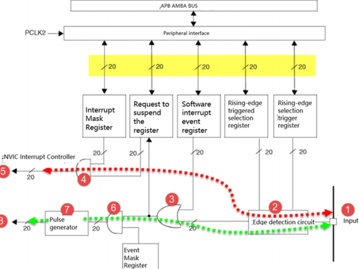
The function block diagram of EXTI includes the core content of EXTI. By mastering the function block diagram, one can have a comprehensive understanding of EXTI and have a very clear thinking when programming. The function block diagram of EXTI is shown in the figure "EXTI Function Block Diagram". In the "EXTI Function Block Diagram" figure, you can see many lines on the signal lines with a slash and marked with "20". This indicates that there are 20 similar signal lines in the controller's internal circuitry. This is consistent with the total of 20 interrupt/event lines of EXTI. Therefore, as long as we understand the principle of one of them, the principles of the other 19 lines will also be known.
EXTI can be divided into two main functions: one is to generate interrupts, and the other is to generate events. These two functions are different in hardware.
First, let's look at the EXTI function block diagram in the figure. The circuit flow indicated by the red dotted line is a line for generating interrupts. The final signal flows into the NVIC controller.
Number 1 is the input line. The EXTI controller has 19 interrupt/event input lines. These input lines can be set to any GPIO through registers, or they can be events from some peripherals. This part will be explained in detail later. The input lines generally contain signals with level changes.
Number 2 is an edge detection circuit. It controls the signal triggering based on the setting of the corresponding bits in the selection registers (EXTI_RTSR) triggered by the rising edge and (EXTI_FTSR) triggered by the falling edge. The edge detection circuit takes the input line as the signal input terminal. If an edge transition is detected, it outputs a valid signal 1 to circuit number 3; otherwise, it outputs an invalid signal 0. The two registers, EXTI_RTSR and EXTI_FTSR, can control which types of level transitions need to be detected, which can be only rising edge triggering, only falling edge triggering, or both rising and falling edge triggering.
Circuit No. 3 is actually an OR gate circuit. One of its inputs comes from Circuit No. 2, and the other input comes from the software interrupt event register (EXTI_SWIER). The EXTI_SWIER enables us to start the interrupt/event line through program control, which is very useful in certain situations. We know that the function of an OR gate is to output 1 if there is a 1 in either input, so either of these two inputs with a valid signal of 1 can output 1 to Circuits No. 4 and No. 6.
Circuit No. 4 is a AND gate circuit. One of its inputs is Circuit No. 3, and the other input comes from the Interrupt Mask Register (EXTI_IMR). The AND gate circuit outputs a 1 only when both inputs are 1. As a result, if EXTI_IMR is set to 0, regardless of whether the output signal of Circuit No. 3 is 1 or 0, the final output signal of Circuit No. 4 will always be 0; if EXTI_IMR is set to 1, the final output signal of Circuit No. 4 will be determined by the output signal of Circuit No. 3. Thus, we can simply control EXTI_IMR to achieve the purpose of generating interrupts. The output signal of Circuit No. 4 will be saved in the Suspend Register (EXTI_PR). If it is determined that the output signal of Circuit No. 4 is 1, the corresponding position in EXTI_PR will be set to 1.
Number 5 involves outputting the contents of the EXTI_PR register to the NVIC, thereby enabling the control of system interrupt events.
Next, let's take a look at the circuit process indicated by the green dotted line. It is a circuit for generating events, and ultimately outputs a pulse signal.
The event generation circuit is different from the interrupt circuit after circuit number 3. The previous circuits were shared. Circuit number 6 is a AND gate, one of whose inputs comes from circuit number 3, and the other input comes from the event masking register (EXTI_EMR). If EXTI_EMR is set to 0, regardless of whether the output signal of circuit number 3 is 1 or 0, the final output signal of circuit number 6 will always be 0; if EXTI_EMR is set to 1, the final output signal of circuit number 6 will be determined by the output signal of circuit number 3. Thus, we can simply control EXTI_EMR to achieve the purpose of generating events.
Number 7 is a pulse generator circuit. It will generate a pulse when its input terminal, which is the output terminal of circuit number 6, receives a valid signal of 1; if the input terminal receives an invalid signal, no pulse will be output.
Number 8 is a pulse signal, which is the final product of the line that triggers the event. This pulse signal can be used by other peripheral circuits, such as the timer TIM, analog-to-digital converter ADC, etc. Such pulse signals are generally used to trigger the start of conversion for TIM or ADC.
The purpose of generating the interrupt line is to input the input signal into the NVIC, and then run the interrupt service function to achieve the function. This is at the software level. While generating the event line is to transmit a pulse signal to other peripheral devices for use, and it is a circuit-level signal transmission, belonging to the hardware level.
Additionally, EXTI is located on the APB2 bus, and this fact needs to be taken into account during programming.
3 Interrupt/Event Line
EXTI has 20 interrupt/event lines. Each GPIO can be set as an input line, occupying EXTI0 to EXTI15. Additionally, there are another seven lines dedicated to specific peripheral events, as shown in the table "EXTI Interrupt_Event Lines".
Four specific peripheral interrupt/event lines are triggered by the peripherals. For detailed usage instructions, please refer to the "W55MH32 Reference Manual" regarding the specific explanations of the peripherals.
Interrupt / Event Line | Input source |
EXTI0 | (X can be A, B, C, D, E, F, G, H, I) |
EXTI1 | (X can be A, B, C, D, E, F, G, H, I) |
EXTI2 | (X can be A, B, C, D, E, F, G, H, I) |
EXTI3 | (X can be A, B, C, D, E, F, G, H, I) |
EXTI4 | (X can be A, B, C, D, E, F, G, H, I) |
EXTI5 | (X can be A, B, C, D, E, F, G, H, I) |
EXTI6 | (X can be A, B, C, D, E, F, G, H, I) |
EXTI7 | (X can be A, B, C, D, E, F, G, H, I) |
EXTI8 | (X can be A, B, C, D, E, F, G, H, I) |
EXTI9 | (X can be A, B, C, D, E, F, G, H, I) |
EXTI10 | (X can be A, B, C, D, E, F, G, H, I) |
EXTI11 | (X can be A, B, C, D, E, F, G, H, I) |
EXTI12 | (X can be A, B, C, D, E, F, G, H, I) |
EXTI13 | (X can be A, B, C, D, E, F, G, H, I) |
EXTI14 | (X can be A, B, C, D, E, F, G, H, I) |
EXTI15 | (X can be A, B, C, D, E, F, G, H, I) |
EXTI16 | PVD Output |
EXTI17 | RTC Alarm Event |
EXTI18 | USB Wake-Up Event |
EXTI19 | Ethernet Wakeup Event (Applicable only to Networked Devices) |
EXTI0 to EXTI15 are used for GPIO. Through programming, any one of the GPIOs can be set as the input source of EXTI. According to the table EXTI Interrupt_Event Lines, EXTI0 can be configured as PA0, PB0, PC0, PD0, PE0, PF0, PG0, PH0 or PI0 by selecting the EXTI0[3:0] bits in the external interrupt configuration register 1 (AFIO_EXTICR1) of AFIO. Refer to the figure EXTI Input Source Selection for details. The configurations for other EXTI lines (EXTI Interrupt/Event lines) are similar.
4 Detailed Explanation of the EXTI Initialization Structure
The standard library functions establish an initialization structure for each peripheral, such as EXTI_InitTypeDef. The members of this structure are used to set the working parameters of the peripheral, and these parameters are set by peripheral initialization configuration functions, such as EXTI_Init(), which are called. These settings will set the corresponding registers of the peripheral to achieve the purpose of configuring the working environment of the peripheral.
The combination of initializing structures and initialization library functions is the essence of the standard library. Once you understand the significance of each member of the initializing structure, you can basically master the use of the peripheral. The initializing structure is defined in the w55mh32_exti.h file, and the initialization library function is defined in the w55mh32_exti.c file. During programming, we can use these functions in combination with the comments in these two files.
Code Listing: EXTI-1 EXTI Initialization Structure
typedef struct {- EXTI_Line:EXTI interrupt/event line selection, selectable from EXTI0 to EXTI19. Refer to the table "EXTI Interrupt/Event Lines Selection" for details.
- EXTI_Mode:EXTI mode selection: It can be set to generate an interrupt (EXTI_Mode_Interrupt) or generate an event (EXTI_Mode_Event).
- EXTI_Trigger:EXTI edge-triggered event, which can be selected as rising edge trigger (EXTI_Trigger_Rising), falling edge trigger (EXTI_Trigger_Falling), or both rising and falling edge triggers (EXTI_Trigger_Rising_Falling).
- EXTI_LineCmd:Control whether to enable the EXTI lines. The option is to enable the EXTI lines (ENABLE) or to disable them (DISABLE).
5 Additional Explanation
Regarding the clarification on the use of external key interrupt, by referring to the interrupt/event lines and input sources table in the tutorial and reference manual, the lines from EXTI0 to EXTI15 can be mapped to using 16 GPIOs for external interrupts. It should be noted that not all of these 16 lines have separate interrupt sources. By checking the w55mh32.h file, the corresponding chip model has EXTI0_IRQn, EXTI1_IRQn, EXTI2_IRQn, EXTI3_IRQn, EXTI4_IRQn, EXTI9_5_IRQn, and EXTI15_10_IRQn. Additionally, by looking at the interrupt functions defined in the startup file, they are also EXTI0_IRQHandler, EXTI1_IRQHandler, EXTI2_IRQHandler, EXTI3_IRQHandler, EXTI4_IRQHandler, EXTI9_5_IRQHandler, and EXTI15_10_IRQHandler.
Once again, we would like to emphasize the supplementary explanation content of the chapter on the overview of W55MH32 interrupt application. NVIC_PriorityGroupConfig is only needed to be set once in the entire program. Once the interrupt priority grouping is set, the interrupt priorities of various peripheral interrupt vectors are interpreted based on the current setting of the grouping.
In other routines, many place NVIC_PriorityGroupConfig in the interrupt configuration function of each peripheral. Some may repeat the statement NVIC_PriorityGroupConfig() in multiple peripheral configuration functions. Here, we remind users that when writing their own programs in the future, they only need to call it once, and from the perspective of code layout logic, it is suitable to place it in the main() function.
WIZnet is a fabless semiconductor company founded in 1998. Its products include the Internet processor iMCU™, which utilizes TOE (TCP/IP Offload Engine) technology and is based on a unique patented fully hardwired TCP/IP. The iMCU™ is designed for embedded Internet devices in various applications.
WIZnet has more than 70 distributors globally and has offices in Hong Kong, South Korea, and the United States, providing technical support and product marketing services.
The regions managed by the Hong Kong office include Australia, India, Turkey, and Asia (excluding South Korea and Japan).