
Chapter 10: Overview of W55MH32 Interrupt Applications
Chapter 10: Overview of W55MH32 Interrupt Applications
Chapter 10: Overview of W55MH32 Interrupt Applications
The reference materials for this chapter are "W55MH32 Reference Manual" and "Cortex-M3 Core Programming Manual" - Chapter 4.3: NVIC and Chapter 4.4: SCB - Section 4.4.5: AIRCR.
The interrupts of W55MH32 are very powerful. Each peripheral can generate an interrupt. Therefore, it is not appropriate to discuss where the interrupts should be explained. Here, we have specially set aside a chapter for a comprehensive summary introduction. Thus, when other chapters involve the knowledge of interrupts, we won't need to spend a lot of space explaining it in detail. We can just give a suggestive overview.
1 Exception type
The W55MH32 incorporates an exception response system at the kernel level, supporting numerous system exceptions and external interrupts. There are 8 system exceptions (if Reset and HardFault are included, it becomes 10), and 60 external interrupts. Except for the priorities of a few exceptions being fixed, the priorities of other exceptions are programmable. The specific system exceptions and external interrupts can be found in the standard library file w55mh32.h, which is the header file. The IRQn_Type structure contains all the exception declarations for the W55MH32 series.
W55MH32 System Error List
Serial Number | Priority | Priority type | Name | Explanation | Address |
| - | - | - | Keep (the actual stored value is the MSP address) | 0X0000 0000 |
-3 | - | Fixed | Reset | Reset | 0X0000 0004 |
-2 | - | Fixed | NMI | Uninterruptible interruption. The RCC clock security system (CSS) is connected to the NMI vector. | 0X0000 0008 |
-1 | - | Fixed | HardFault | All types of errors | 0X0000 000C |
0 | - | Programmable | MemManage | Memory management | 0X0000 0010 |
1 | - | Programmable | BusFault | Prefetch failed, memory access failed. | 0X0000 0014 |
2 | - | Programmable | UsageFault | Undefined instructions or illegal states | 0X0000 0018 |
| - | - | - | Maintain | 0X0000 001C-0X0000 002B |
3 | - | Programmable | SVCall | The system services called through the SWI instruction | 0X0000 002C |
4 | - | Programmable | Debug Monitor | Debugging monitor | 0X0000 0030 |
| - | - | - | Maintain | 0X0000 0034 |
5 | - | Programmable | PendSV | System services that can be suspended | 0X0000 0038 |
6 | - | Programmable | SysTick | System Tick Timer | 0X0000 003C |
W55MH32 External Interrupt List
Serial Number | Priority
| Priority type
| Name | Explanation | Address
|
0 | 7 | Programmable
| WWDG | Window watchdog interrupt | 0X0000 0040 |
1 | 8 | Programmable
| PVD | Power voltage detection (PVD) interrupt connected to EXTI | 0X0000 0044 |
2 | 9 | Programmable
| TAMPER | Intrusion Detection Interruption | 0X0000 0048 |
57 | 64 | Programmable
| DMA2 Channel 2 | DMA2 Channel 2 Interrupt | 0X0000 0124 |
58 | 65 | Programmable
| DMA2 Channel 3 | DMA2 channel 3z interrupt | 0X0000 0128 |
59 | 66 | Programmable
| DMA2 Channel 4_5 | DMA2 channel 4 and channel 5 interrupts | 0X0000 012C |
2 Introduction to NVIC
Before discussing how to configure interrupt priorities, we need to first understand the NVIC. The NVIC is a nested vector interrupt controller that controls all the interrupt-related functions of the entire chip. It is closely coupled with the kernel and is a peripheral within the kernel. However, different chip manufacturers will trim the NVIC in the Cortex-M3 kernel when designing the chips, removing the unnecessary parts. Therefore, the NVIC of the W55MH32 is a subset of the NVIC of the Cortex-M3.
2.1 Introduction to NVIC Registers
In the firmware library, the structure definition of NVIC is quite forward-looking. It reserves many bits for each register, presumably to facilitate future functionality expansion. However, the W55MH32 cannot utilize so many bits; it only uses a portion of them. The specific amount used can be referred to in the "Cortex-M3 Core Programming Manual" - 4.3.11: NVIC Register Mapping.
Code listing: Definition of NVIC structure for interrupt - 1, from the firmware library header file: core_cm3.h
typedef struct {
__IO uint32_t ISER[8]; When configuring interrupts, we usually only use the three registers: ISER, ICER and IP. ISER is used to enable interrupts, ICER is used to disable interrupts, and IP is used to set the interrupt priority.
2.2 NVIC Interrupt Configuration Firmware Library
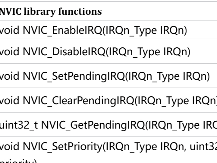
At the end of the firmware library file core_cm3.h, some functions of the NVIC are also provided. These functions follow the CMSIS rules and can be used by any Cortex-M3 processor. The details are as follows:
NVIC library functions | Description |
void NVIC_EnableIRQ(IRQn_Type IRQn) | Enable interrupt |
void NVIC_DisableIRQ(IRQn_Type IRQn) | Disability interruption |
void NVIC_SetPendingIRQ(IRQn_Type IRQn) | Set the interrupt suspension position |
void NVIC_ClearPendingIRQ(IRQn_Type IRQn) | Clear the interrupt suspend state |
uint32_t NVIC_GetPendingIRQ(IRQn_Type IRQn) | Obtain the suspended interrupt number |
void NVIC_SetPriority(IRQn_Type IRQn, uint32_t priority) | Set interrupt priority |
uint32_t NVIC_GetPriority(IRQn_Type IRQn) | Obtain interrupt priority |
void NVIC_SystemReset(void) | System reset |
These library functions are rarely used in our programming, and in some cases, we don't even use them at all. When configuring interrupts, we have a more concise method. Please refer to the section on interrupt programming.
3 Definition of Priority
3.1 Definition of Priority
In the NVIC, there is a dedicated register: the interrupt priority register NVIC_IPRx, which is used to configure the priority of external interrupts. The IPR width is 8 bits. In principle, each external interrupt can have a priority ranging from 0 to 255. The smaller the value, the higher the priority. However, most CM3 chips have a simplified design, resulting in a reduction in the actual number of supported priorities. In the W55MH32, only the high 4 bits are used, as shown below:
bit7 | bit6 | bit5 | bit4 | bit3 | bit2 | bit1 | bit0 |
Used to express priority | Not used. Reading back is 0. | ||||||
The 4 bits used to express the priority are divided into preemption priority and sub-priority. If more than one interrupt responds at the same time, the one with higher preemption priority will preempt the one with lower preemption priority, and if the preemption priority is the same, the sub-priority will be compared. If the preemption priority and sub-priority are the same, then compare their hardware interrupt numbers, the smaller the number, the higher the priority.
3.2 Priority Grouping
The grouping of priorities is determined by the PRIGROUP[10:8] bits of the Application Interrupt and Reset Control Register AIRCR of the kernel peripheral SCB, and the W55MH32 is divided into five groups as follows: main priority = preemption priority.
PRIGROUP[2:0] | Interrupt priority value PRI_N [7:4] (binary point) | Primary priority level | Subordinate priority bit | Primary priority | Subordinate priority |
0b 011 | 0b xxxx | [7:4] | None | 16 | None |
0b 100 | 0b xxx.y | [7:5] | [4] | 8 | 2 |
0b 101 | 0b xx.yy | [7:6] | [5:4] | 4 | 4 |
0b 110 | 0b x.yyy | [7] | [6:4] | 2 | 9 |
0b 111 | 0b .yyyy | None | [7:4] | None | 16 |
The priority grouping can be implemented by calling the library function NVIC_PriorityGroupConfig(). The library functions related to NVIC interrupts are all in the library files misc.c and misc.h.
Code listing: Interrupt - 2 Interrupt Priority Grouping Library Function NVIC_PriorityGroupConfig()
/**
/**Priority grouping | Primary priority | Subordinate priority | Description |
NVIC_PriorityGroup_0 | 0 | 0-15 | Master - 0 bit, Slave - 4 bit |
NVIC_PriorityGroup_1 | 0-1 | 0-7 | Master - 1 bit, Slave - 3 bits |
NVIC_PriorityGroup_2 | 0-3 | 0-3 | Master - 2 bits, Slave - 2 bits |
NVIC_PriorityGroup_3 | 0-7 | 0-1 | Master - 3 bits, Slave - 1 bit |
NVIC_PriorityGroup_4 | 0-15 | 0 | Master - 4 bits, Slave - 0 bits |
4 Interrupt programming
When configuring each interrupt, there are generally three programming points:
1. Enable a certain interrupt of the peripheral. This is specifically controlled by the relevant interrupt enable bit of each peripheral. For example, the serial port has a transmission completion interrupt and a reception completion interrupt. Both of these interrupts are controlled by the relevant interrupt enable bits of the serial port control register.
2. Initialize the NVIC_InitTypeDef structure, configure the interrupt priority group, set the preemption priority and sub-priority, and enable the interrupt request. The NVIC_InitTypeDef structure is defined in the header file misc.h of the firmware library.
Code Listing: Interrupt - 3 NVIC Initialization Structure
typedef struct {
uint8_t NVIC_IRQChannel; Let's explain each member of the NVIC initialization structure one by one:
(1). NVIC_IROChannel: This is used to set the interrupt source. Different interrupt sources are different and cannot be wrongly set. Even if it is wrongly set, the program will not report an error, but will only result in not responding to the interrupt. The specific configuration of the members can be referred to the IRQn_Type structure defined in the w55mh32x.h header file. This structure contains all the interrupt sources.
Code Listing: Interrupt - 4 IRQn_Type Interrupt Source Structure
typedef enum IRQn {(2). NVIC_IRQChannelPreemptionPriority: Preemption priority. The specific value should be determined according to the priority group. Please refer to the table "Priority Group Truth Table" for details.
(3). NVIC_IRQChannelSubPriority: Sub-priority. The specific value should also be determined according to the priority group. Please refer to the table "Priority Group Truth Table" for details.
(4). NVIC_IRQChannelCmd: Interrupt enable (ENABLE) or disable (DISABLE). This operates on the registers NVIC_ISER and NVIC_ICER.
3. Writing Interrupt Service Functions
In the startup file startup_w55mh32_hd.s, we have pre-written an interrupt service function for each interrupt. However, these interrupt functions are all empty and are only used to initialize the interrupt vector table. The actual interrupt service functions need to be rewritten by us. To facilitate management, we have unified the writing of these interrupt service functions in the library file w55mh32_it.c.
The function name of the interrupt service function must be the same as that set in the startup file. If it is written incorrectly, the system will not be able to find the entry of the interrupt service function in the interrupt vector table, and will directly jump to the empty function pre-written in the startup file, resulting in an infinite loop and the inability to implement the interrupt.
5 Additional Explanation
The custom functions for the configuration of certain peripherals in subsequent other routines, such as NVIC_Configuration(), respectively execute the functions NVIC_PriorityGroupConfig() to configure the interrupt priority group, and NVIC_Init(&NVIC_InitStructure) to assign the interrupt vector and its priority that will be set. Note that NVIC_PriorityGroupConfig is only needed to be set once throughout the entire program.
After the interrupt priority group is set, the interrupt priorities of the corresponding interrupt vectors for various peripherals are interpreted based on the currently set group. For example, if configured as NVIC_PriorityGroup_0 or NVIC_PriorityGroup_4, it is invalid to fill the sub-priority or main priority of NVIC_InitStructure for multiple peripherals separately. Therefore, if there are many peripheral interrupts in the project, after determining which priority group to use, the priority of the interrupt vector for each peripheral should be configured separately.
In other routines, many write NVIC_PriorityGroupConfig in the interrupt configuration functions of each peripheral. Some may repeat the statement NVIC_PriorityGroupConfig() in multiple peripheral configuration functions. Here, it is reminded that when writing your own program, you only need to call it once. Repeated calling is equivalent to repeatedly assigning values to the interrupt-related registers multiple times and taking the last assignment. From the perspective of code layout logic, NVIC_PriorityGroupConfig is suitable to be placed in the main() function.
WIZnet is a fabless semiconductor company founded in 1998. Its products include the Internet processor iMCU™, which utilizes TOE (TCP/IP Offload Engine) technology and is based on a unique patented fully hardwired TCP/IP. The iMCU™ is designed for embedded Internet devices in various applications.
WIZnet has more than 70 distributors globally and has offices in Hong Kong, South Korea, and the United States, providing technical support and product marketing services.
The regions managed by the Hong Kong office include Australia, India, Turkey, and Asia (excluding South Korea and Japan).