
9. W5100S/W5500+RP2040 Raspberry Pi Pico<SNTP Get Network Time>
9. W5100S/W5500+RP2040 Raspberry Pi Pico<SNTP Get Network Time>

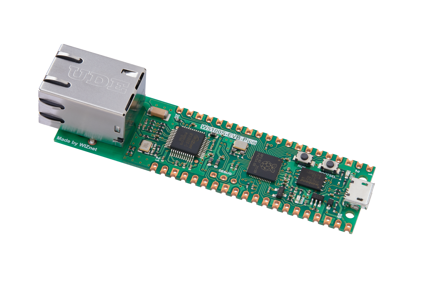
WIZnet - W5100S-EVB-Pico
x 1
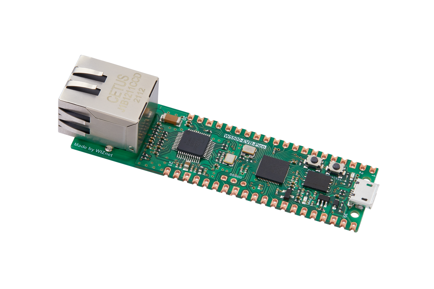
WIZnet - W5500-EVB-Pico
x 1
1 Introduction
With the continuous advancement of technology and changing application requirements, the SNTP protocol is also facing some challenges and opportunities. As network technology becomes more popular and IoT devices increase, the demand for more accurate time synchronization and more efficient synchronization methods will also increase.
W5100S/W5500 is an embedded Ethernet controller integrating a full hardware TCP/IP protocol stack. It is also an industrial-grade Ethernet control chip. This tutorial will introduce the basic principles, usage steps, application examples and precautions of W5100S/W5500 Ethernet SNTP application to help readers better master this technology.
2 Introduction to the protocol
2.1 What is SNTP
SNTP (Simple Network Time Protocol) is a simplified version of the Network Time Protocol. It is a protocol used to synchronize computer time on network computers.
SNTP protocol adopts client/server working mode and can operate in unicast or broadcast mode. The SNTP server uses GPS signals or its own atomic clock as the system's time base. In unicast mode, the SNTP client can obtain accurate time information by regularly accessing the SNTP server, which can be used to adjust the time of the client's own system to achieve time synchronization.
2.2 Advantages of SNTP
The advantages of SNTP mainly include:
High accuracy: SNTP can provide highly accurate time synchronization, it can synchronize computer clocks with global satellite networks. This synchronization can achieve an accuracy of 10 milliseconds, which is very important for operations such as computer system logs, file backup and restore.
Network delay adaptation: SNTP can automatically adapt to changes in network delay. When network latency changes, SNTP can automatically adjust timestamps to ensure that all computers are synchronized to the correct time.
Lightweight: Compared with NTP, SNTP is a lightweight protocol and the amount of data it transmits in the network is very small. This makes SNTP very suitable for low-bandwidth, high-latency network environments
2.3 SNTP principle
The working principle is a client/server mode, which can operate in unicast (point-to-point) or broadcast (point-to-multipoint) mode. The SNTP server uses GPS signals or its own atomic clock as the system's time base.
In unicast mode, the SNTP client can obtain accurate time information by regularly accessing the SNTP server, which can be used to adjust the time of the system where the client is located to achieve time synchronization.
In broadcast mode, the SNTP server will periodically send messages to the specified IP broadcast address or IP multicast address, and the SNTP client will obtain time information by listening to these addresses.
There are generally many SNTP servers in the network, and the client will select the best servers to use through a certain algorithm. If an SNTP server loses the external time source during work, the SNTP server will tell the SNTP client "I lost the external time". When the SNTP client receives this information, it will discard the time information sent to it by the failed SNTP server, and then reselect another SNTP server.
2.4 Application scenarios
The SNTP protocol is widely used in the following scenarios:
Network device time synchronization: Network devices such as routers and switches use the SNTP protocol to synchronize time to ensure that network devices have consistent time standards.
Logging: Servers, computers and other systems use the SNTP protocol to synchronize time to ensure that the time recorded in the log is accurate.
E-commerce: E-commerce systems use the SNTP protocol to synchronize time to ensure time consistency for operations such as orders and transactions.
In addition to the above, SNTP is also used in fields such as computer network simulation, military simulation, and urban simulation. The SNTP calculation method can be used to simulate various network topologies, protocols, and traffic, as well as battlefield environments and combat operations, providing networks in these fields. Provide support for design and optimization, military decision-making, urban transportation, etc.
3 WIZnet Ethernet chip
WIZnet mainstream hardware protocol stack Ethernet chip parameter comparison
| Model | Embedded Core | Host I/F | TX/RX Buffer | HW Socket | Network Performance |
|---|---|---|---|---|---|
| W5100S | TCP/IPv4, MAC & PHY | 8bit BUS, SPI | 16KB | 4 | Max.25Mbps |
| W6100 | TCP/IPv4/IPv6, MAC & PHY | 8bit BUS, Fast SPI | 32KB | 8 | Max.25Mbps |
| W5500 | TCP/IPv4, MAC & PHY | Fast SPI | 32KB | 8 | Max 15Mbps |
W5100S/W6100 supports 8-bit data bus interface, and the network transmission speed will be better than W5500.
W6100 supports IPV6 and is compatible with W5100S hardware. If users who already use W5100S need to support IPv6, they can be Pin to Pin compatible.
W5500 has more Sockets and send and receive buffers than W5100S.
4 SNTP network setting example overview and usage
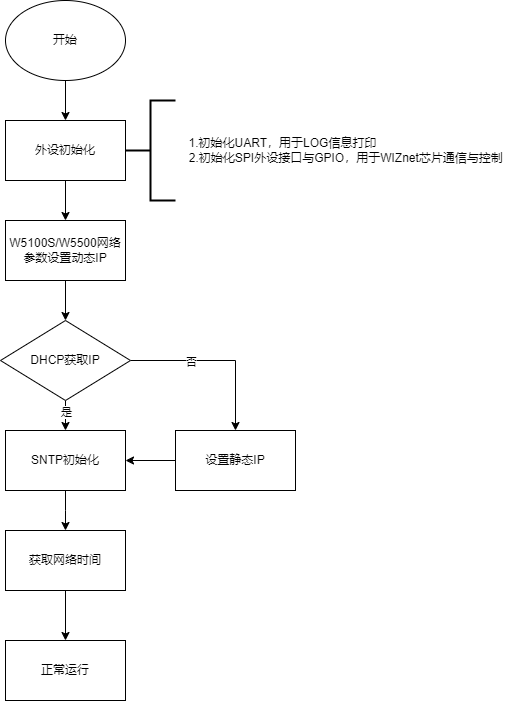
4.1 Flowchart
The running block diagram of the program is as follows:
4.2 Core preparation work
Software:
Visual Studio Code
WIZnet UartTool
Hardware:
W5100SIO module + RP2040 Raspberry Pi Pico development board or WIZnet W5100S-EVB-Pico development board
Micro USB interface data cable
TTL to USB
cable
4.3 Connection method
Connect the USB port of the PC through the data cable (mainly used for burning programs, but can also be used as a virtual serial port)
Convert TTL serial port to USB and connect the default pin of UART0:
RP2040 GPIO0 (UART0 TX) <----> USB_TTL_RX
RP2040 GPIO1 (UART0 RX) <----> USB_TTL_TX
When using module connection RP2040 for wiring
RP2040 GPIO16 <----> W5100S MISO
RP2040 GPIO17 <----> W5100S CS
RP2040 GPIO18 <----> W5100S SCK
RP2040 GPIO19 <----> W5100S MOSI
RP2040 GPIO20 <----> W5100S RST
Connect the PC and device to the router LAN port through network cables
4.4 Main code overview
We are using the official ioLibrary_Driver library of WIZnet. The library supports rich protocols and is easy to operate. The chip integrates the TCP/IP protocol stack on the hardware. The library also encapsulates the protocols above the TCP/IP layer. We only need to simply call the corresponding function to complete the application of the protocol. .
Step 1: Add the corresponding .h file to the sntp_client.c file.
Step 2: Define the macros required for DHCP configuration.
Step 3: Configure the network information and the server to obtain the network time, and configure the time zone. The East Eighth District is configured here. You can find the number of the East Eighth District in the sntp.c file, which is 39.
Step 4: Write a timer callback processing function for the DHCP 1s tick timer processing function.
Step 5: The main function first initializes the serial port and SPI, and then writes the network configuration parameters of W5100S. After initializing DHCP, it starts DHCP to obtain the IP. When obtained, it prints the obtained IP. When the number of acquisitions exceeds the maximum number of acquisitions, static is used. IP, and then initialize the SNTP incoming socket number, server IP, time zone number, and cache buff. The main loop executes to obtain the network time and prints a message every second.
// DHCP retry times
wiz_NetInfo net_info = {
.mac = {0x00, 0x08, 0xdc, 0x16, 0xed, 0x2e}, // Define MAC variables
.ip = {192, 168, 1, 10}, // Define IP variables
.sn = {255, 255, 255, 0}, // Define subnet variables
.gw = {192, 168, 1, 1}, // Define gateway variables
.dns = {8, 8, 8, 8}, // Define DNS variables
.dhcp = NETINFO_DHCP}; // Define the DNCP mode
wiz_NetInfo get_info;
static uint8_t ethernet_buf[ETHERNET_BUF_MAX_SIZE] = {
0,
};
static uint8_t sntp_server_ip[4] = {202, 112, 10, 60};
static uint16_t timezone = 39;
static uint8_t sntp_get_ip_count = 0;
datetime date;
static uint8_t dhcp_get_ip_flag = 0; // Define the DHCP acquisition flag
/**
* @brief Timer callback processing function, used for dhcp timing processing
* @param repeating :Timer structure
* @return bool
*/
bool repeating_timer_callback(struct repeating_timer *t);
/**
* @brief Initialization of chip network information
* @param conf_info :Static configuration information
* @return none
*/
void network_init(wiz_NetInfo *conf_info);
int main()
{
struct repeating_timer timer; // Define the timer structure
/*mcu init*/
stdio_init_all(); // Initialize the main control peripheral
wizchip_initialize(); // spi initialization
/*dhcp init*/
DHCP_init(SOCKET_ID, ethernet_buf); // DHCP initialization
add_repeating_timer_ms(1000, repeating_timer_callback, NULL, &timer); // Add DHCP 1s Tick Timer handler
network_init(&net_info); // Configuring Network Information
print_network_information(&get_info); // Read back the configuration information and print it
/*sntp init*/
SNTP_init(SOCKET_ID, sntp_server_ip, timezone, ethernet_buf); // NTP protocol initialization parameters
printf("wiznet chip sntp client example.\r\n");
while (true)
{
sntp_get_ip_count++;
sleep_ms(1000); // Print once a second
SNTP_run(&date); // The NTP protocol obtains the current time from the server at the time of authorization
if (sntp_get_ip_count > 2)
{
printf("NOW: %d-%d-%d %d:%d:%d\r\n", date.yy, date.mo, date.dd, date.hh, date.mm, date.ss);
}
}
}4.5 Results demonstration
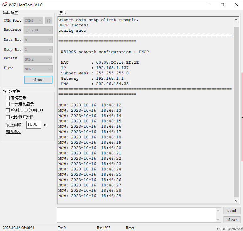
Open WIZ UartTool, fill in the parameters: select the COM Port corresponding to the serial port, baud rate 115200, 8 data bits, 1 stop bit, no check bit, no flow control, click open after filling in the parameters.
After pressing reset, you will see that the serial port prints the network time every second, indicating that the network time is obtained successfully.
5 Precautions
You need to choose a trustworthy network time server and make sure that the selected server supports the network time protocol you use.
To ensure that the output times are consistent across different time zones, you should use the corresponding time zone number. You can select a specific time zone using the timezone number.
If we want to use WIZnet's W5500 to implement the example in this chapter, we only need to modify two places:
(1) Find the wizchip_conf.h header file under library/ioLibrary_Driver/Ethernet/, and modify the WIZCHIP macro definition to W5500;
(2) Find the CMakeLists.txt file under library and set COMPILE_SEL to ON. OFF is W5100S and ON is W5500.
-
Code for this article

-
WIZnet Official Website
-
WIZnet Official IOlibrary
-
YouTube Video