32. W5100S/W5500+RP2040 Raspberry Pi Pico<UPnP Example>
32. W5100S/W5500+RP2040 Raspberry Pi Pico<UPnP Example>

1 Introduction
With the rapid development of smart home, Internet of Things and other technologies, the application prospects of UPnP technology will be broader. In the future, with the continuous advancement of technology and the continuous expansion of application scenarios, UPnP technology is expected to become one of the core protocols for connecting various devices, thereby bringing users a smarter and more convenient network experience.
W5100S/W5500 is an embedded Ethernet controller integrating a full hardware TCP/IP protocol stack. It is also an industrial-grade Ethernet control chip. This tutorial will introduce the basic principles, usage steps, application examples and precautions of W5100S/W5500 Ethernet UPnP application to help readers better master this technology.
2 Protocol Introduction
2.1 What is UPnP?
UPnP (Universal Plug and Play) is a network protocol promoted by the "Universal Plug and Play Forum" (UPnP™ Forum), which aims to enable various devices (such as devices in home networks and corporate networks) to communicate with each other without interruption. seamless connections and simplify the implementation of related networks.
The goal of UPnP is to enable peer-to-peer network connections around the world for a variety of smart devices, wireless devices, and personal computers. It supports protocols such as TCP/IP, UDP and HTTP, and is a distributed and open network architecture.
2.2 Advantages of UPnP
The advantages of UPnP mainly include:
Automatic configuration: UPnP can automatically configure network devices so that they can communicate in the network, eliminating the need for tedious operations such as manual port mapping. This greatly simplifies the installation and use of the device and reduces the complexity of network configuration.
Simplify user experience: UPnP allows users to use network devices and applications more conveniently, providing a better user experience. Since UPnP does not require any configuration by the user, the user only needs to simply connect the device to the network, and the device can automatically obtain an IP address and communicate with other devices.
Multi-device interconnection: UPnP supports interconnection between multiple devices, making communication and resource sharing between devices easier and more convenient. This allows users to easily connect multiple devices together to achieve richer application scenarios.
Remote access: UPnP supports remote access, enabling users to access their devices and resources from anywhere. No matter where the user is, as long as they can connect to the network, they can control and operate the devices in their home.
2.3 UPnP data interaction principle
The interaction process of UPnP includes the following links:
Address allocation: After the device is connected to the network, it obtains an IP address automatically or manually.
Discovery phase: The device broadcasts its presence on the network and looks for other devices and services.
Description phase: The device provides detailed service and function description information to the control point.
Control phase: The device controls other devices or obtains their status information by sending request messages.
Event phase: The device sends event messages to the control point to report its status changes or other important events.
Expression phase: The device provides detailed device and service information to the control point so that other devices can understand and utilize this information.
2.4 UPnP application scenarios
UPnP application scenarios include but are not limited to the following:
Smart home: UPnP can be used to interconnect smart home devices to achieve automated control and remote control. For example, through the UPnP protocol, users can use their mobile phones or computers to control lighting, TV, air conditioning and other equipment at home, and can also set scheduled tasks for the equipment.
Internet of Things: In the field of Internet of Things, UPnP can be used to realize interconnection and intelligent management of devices. For example, in smart agriculture, farmland monitoring equipment, greenhouse monitoring equipment, etc. can be connected through the UPnP protocol to achieve real-time monitoring and remote control of agricultural information.
Multimedia home gateway: UPnP can be used to connect various transmission media to the home LAN to achieve interconnection and control. For example, users can watch high-definition movies or listen to lossless music at home while enjoying the convenience of fast network connections.
Smart home devices: UPnP can be used for interconnection and communication of smart home devices, such as smart speakers, smart light bulbs, etc. Users can control devices at home through voice control or mobile APP, enjoying a more convenient life experience.
Secure device serial connection: UPnP can implement digital signature and authentication functions to ensure the security of device data. For example, an IP camera that supports UPnP can automatically configure the LAN environment, and digital signature and authentication functions can also be implemented on UPnP to ensure the security of device data.
3 WIZnet Ethernet chip
WIZnet mainstream hardware protocol stack Ethernet chip parameter comparison
| Model | Embedded Core | Host I/F | TX/RX Buffer | HW Socket | Network Performance |
|---|---|---|---|---|---|
| W5100S | TCP/IPv4, MAC & PHY | 8bit BUS, SPI | 16KB | 4 | Max.25Mbps |
| W6100 | TCP/IPv4/IPv6, MAC & PHY | 8bit BUS, Fast SPI | 32KB | 8 | Max.25Mbps |
| W5500 | TCP/IPv4, MAC & PHY | Fast SPI | 32KB | 8 | Max 15Mbps |
W5100S/W6100 supports 8-bit data bus interface, and the network transmission speed will be better than W5500.
W6100 supports IPv6 and is compatible with W5100S hardware. If users who already use W5100S need to support IPv6, they can be Pin to Pin compatible.
W5500 has more Sockets and send and receive buffers than W5100S.
4 UPnP example overview and usage
4.1 Flowchart
The running block diagram of the program is as follows:
4.2 Core preparation work
Software
Visual Studio Code
WIZnet UartTool
Socket Tester
Hardware
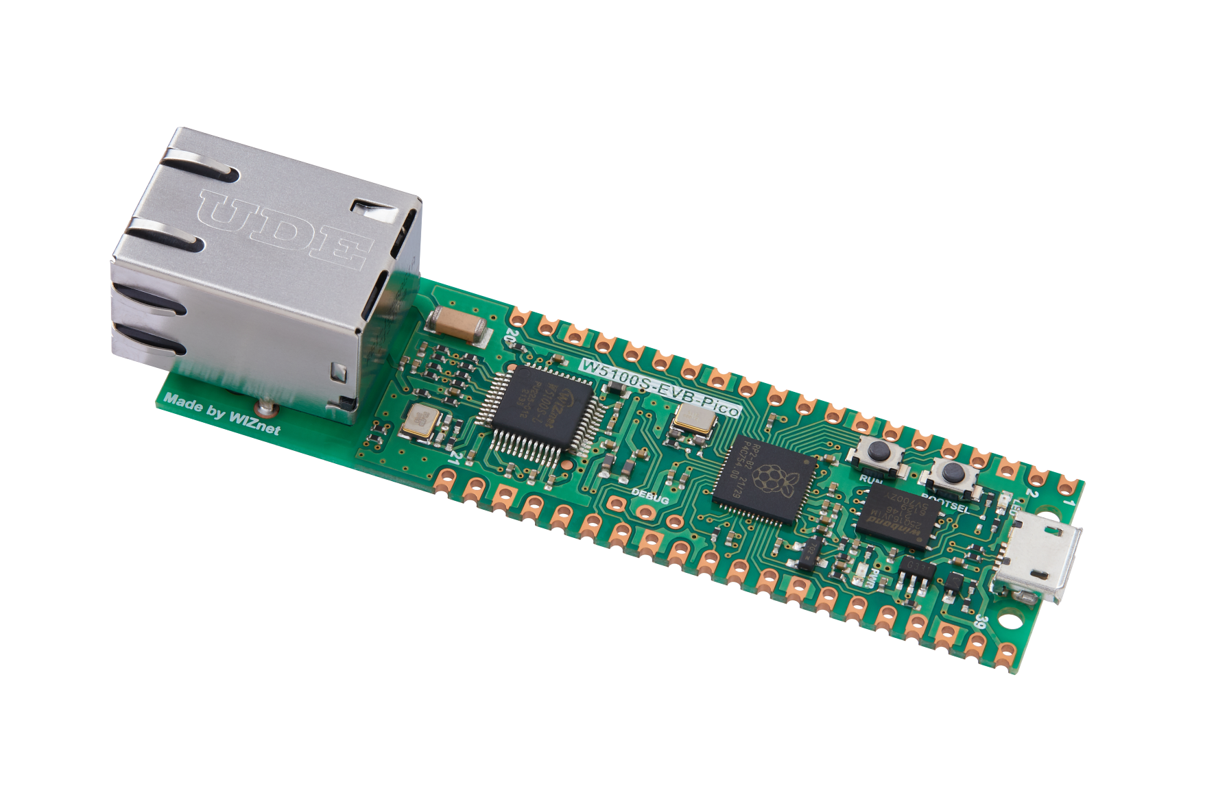
W5100SIO module + RP2040 Raspberry Pi Pico development board or WIZnet W5100S-EVB-Pico development board
Micro USB interface data cable
TTL to USB
cable
Routers that support UPNP
4.3 Connection method
Connect the USB port of the PC through the data cable (mainly used for burning programs, but can also be used as a virtual serial port)
Convert TTL serial port to USB and connect the default pin of UART0:
RP2040 GPIO 0 (UART0 TX) <----> USB_TTL_RX
RP2040 GPIO 1 (UART0 RX) <----> USB_TTL_TX
When wiring using module connection RP2040
RP2040 GPIO 16 <----> W5100S MISO
RP2040 GPIO 17 <----> W5100S CS
RP2040 GPIO 18 <----> W5100S SCK
RP2040 GPIO 19 <----> W5100S MOSI
RP2040 GPIO 20 <----> W5100S RST
Connect the PC and device to the router LAN port through network cables
4.4 Main code overview
We are using the official ioLibrary_Driver library of WIZnet. The library supports rich protocols and is easy to operate. The chip integrates the TCP/IP protocol stack on the hardware. The library also encapsulates the protocols above the TCP/IP layer. We only need to simply call the corresponding function to complete the application of the protocol. .
Step 1: Add the corresponding header file to the upnp_run.c file.
Step 2: Define relevant macros, including socket port number, transceiver buffer size, number of retries after DHCP failure, and LED light pin number.
Step 3: Declare relevant functions, including timer callback functions for DHCP and UPNP 1s timing processing; network information initialization, obtain network information through DHCP, and statically configure network information if it fails; LED initialization and LED light status control; and Initialized related variables, etc.
Step 4: Enter the main function and first define the variables and initialize the serial port and spi interface, then fragment the socket transceiver cache and write the configuration information, then initialize the LED and DHCP, and start the 1s timer, giving priority to configuring the network information through DHCP. If it fails, static network information will be used; after the configuration is completed, discover the device (IGD) through SSDP, then obtain the device description and subscribe to the event message. After success, enter the menu interface to select the operation event; as shown below:
// Use dhcp
// Use socket
// Use upnp
// Socket number
// Send and receive cache size
// DHCP retry times
// Onboard led pin
/**
* @brief Timer callback processing function, used for dhcp timing processing
* @param repeating :Timer structure
* @return bool
*/
bool repeating_timer_callback(struct repeating_timer *t);
/**
* @brief Initialization of chip network information
* @param conf_info :Static configuration information
* @return none
*/
void network_init(wiz_NetInfo *conf_info);
/**--
* @brief Initiallization led and Registration function
* @param none
* @return none
*/
void UserLED_Init(void);
/**
* @brief set led status, in order to adapt data format, see details the file: snmp_custom.c 's snmpData[]
* @param val: 0 -> led off, 1 -> led on
* @return none
*/
void setUserLEDStatus(uint8_t val);
/* Network information to be configured. */
wiz_NetInfo net_info = {
.mac = {0x00, 0x08, 0xdc, 0x1e, 0xed, 0x2e}, // Configured MAC address
.ip = {192, 168, 1, 10}, // Configured IP address
.sn = {255, 255, 255, 0}, // Configured subnet mask
.gw = {192, 168, 1, 1}, // Configured gateway
.dns = {8, 8, 8, 8}, // Configured domain address
.dhcp = NETINFO_DHCP}; // Configured dhcp model,NETINFO_DHCP:use dhcp; NETINFO_STATIC: use static ip.
static uint8_t ethernet_buf[ETHERNET_BUF_MAX_SIZE] = {
0,
}; // Send and receive cache
static uint8_t breakout_flag = 0; // Define the DHCP acquisition flag
static uint16_t tcps_port = 8000;
static uint16_t udps_port = 5000;
static uint8_t tx_size[_WIZCHIP_SOCK_NUM_] = {4, 2, 2, 0};
static uint8_t rx_size[_WIZCHIP_SOCK_NUM_] = {4, 2, 2, 0};
static uint8_t tx_size[_WIZCHIP_SOCK_NUM_] = {4, 4, 2, 1, 1, 1, 1, 2};
static uint8_t rx_size[_WIZCHIP_SOCK_NUM_] = {4, 4, 2, 1, 1, 1, 1, 2};
int main()
{
struct repeating_timer timer; // Define the timer structure
wiz_NetInfo get_info; // Stores the read configuration information
/* MCU init */
stdio_init_all(); // Initialize the main control peripheral
wizchip_initialize(); // Initialize the chip interface
/* socket rx and tx buff init */
wizchip_init(tx_size, rx_size);
wizchip_setnetinfo(&net_info); // Configure once first
/* Onboard LED init*/
UserLED_Init();
/*dhcp init*/
DHCP_init(SOCKET_ID, ethernet_buf); // DHCP initialization
add_repeating_timer_ms(1000, repeating_timer_callback, NULL, &timer); // Add DHCP 1s Tick Timer handler
printf("wiznet chip upnp example.\r\n");
network_init(&net_info); // Configuring Network Information
print_network_information(&get_info); // Read back the configuration information and print it
do
{
printf("Send SSDP.. \r\n");
} while (SSDPProcess(SOCKET_ID) != 0); // SSDP Search discovery
if (GetDescriptionProcess(SOCKET_ID) == 0) // GET IGD description
{
printf("GetDescription Success!!\r\n");
}
else
{
printf("GetDescription Fail!!\r\n");
}
if (SetEventing(SOCKET_ID) == 0) // Subscribes IGD event messageS
{
printf("SetEventing Success!!\r\n");
}
else
{
printf("SetEventing Fail!!\r\n");
}
Main_Menu(SOCKET_ID, SOCKET_ID + 1, SOCKET_ID + 2, ethernet_buf, tcps_port, udps_port); // Main menu
}
4.5 Results demonstration
DHCP obtains IP successfully:
Adding port mapping successfully:
Running the TCP Server loopback test successfully:
5 Precautions
Note that the socket cache fragments must be large enough to avoid being too small, resulting in incomplete received data and errors during data packet parsing;
Define the size of the temporary storage (cache) array used for sending and receiving to be greater than or equal to the corresponding socket cache size;
The router must have upnp function and must be turned on during debugging;
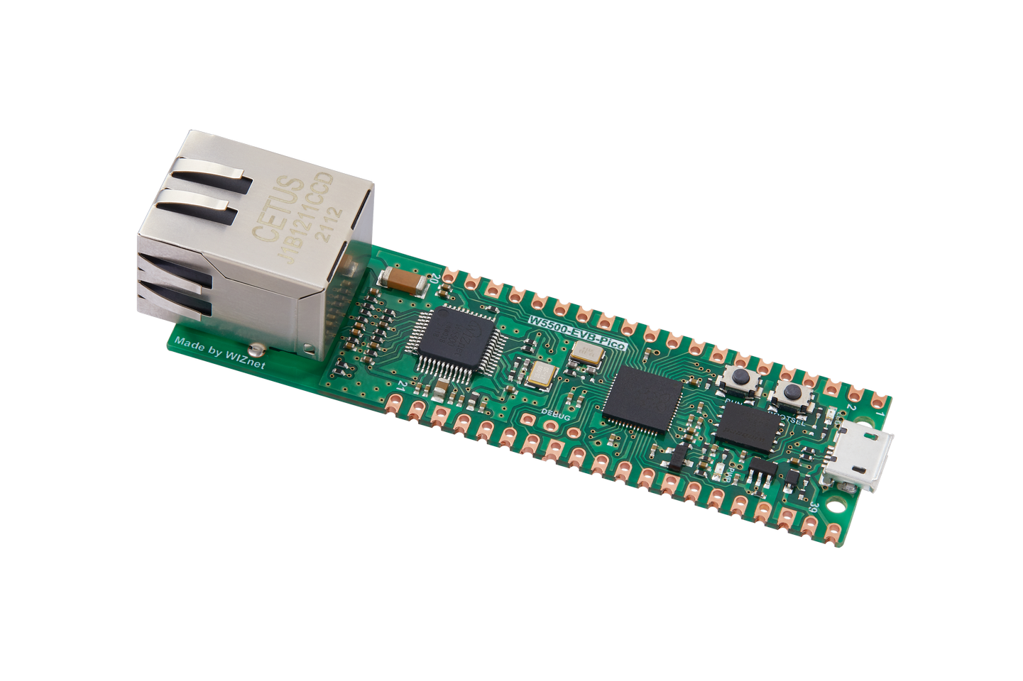
If we want to use WIZnet's W5500 to implement the example in this chapter, we only need to modify two places:
(1) Find the wizchip_conf.h header file under library/ioLibrary_Driver/Ethernet/ and modify the WIZCHIP macro definition to W5500.
(2) Find the CMakeLists.txt file under library and set COMPILE_SEL to ON. OFF is W5100S and ON is W5500.


