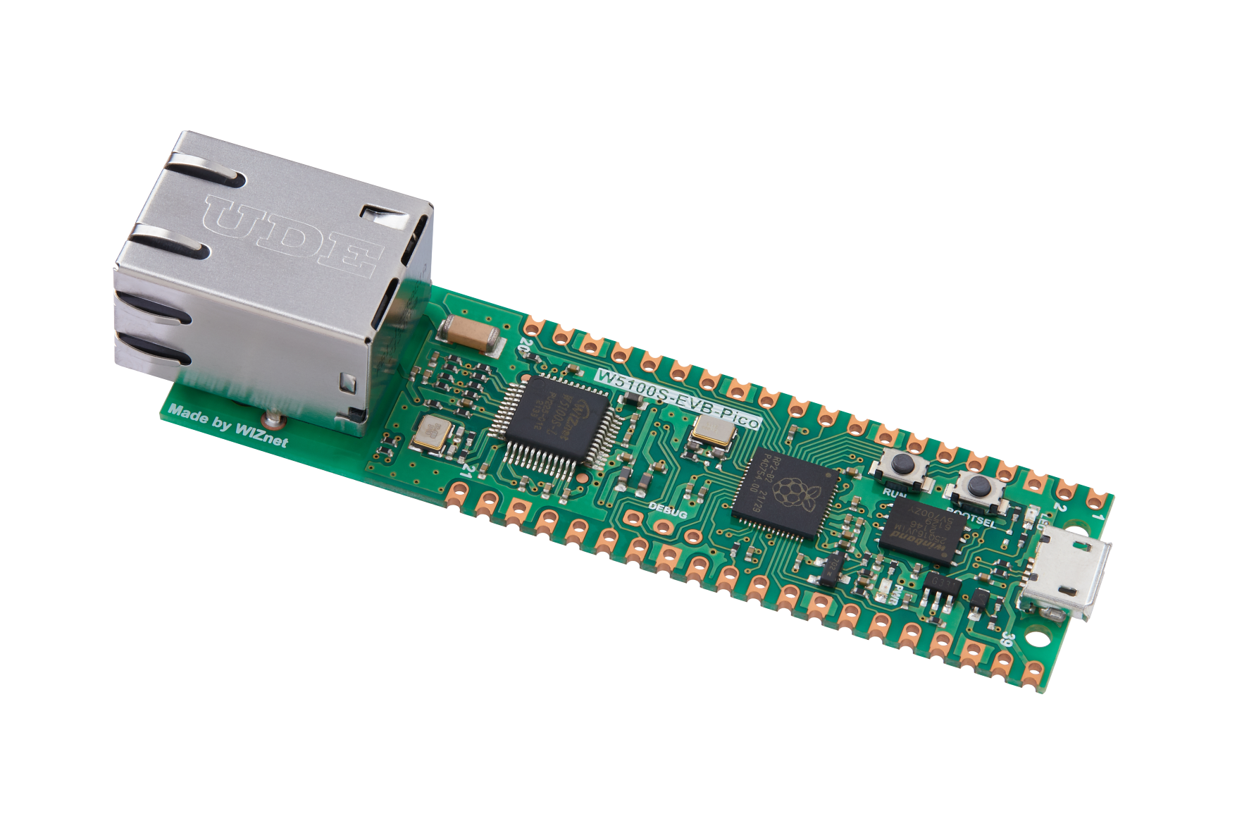
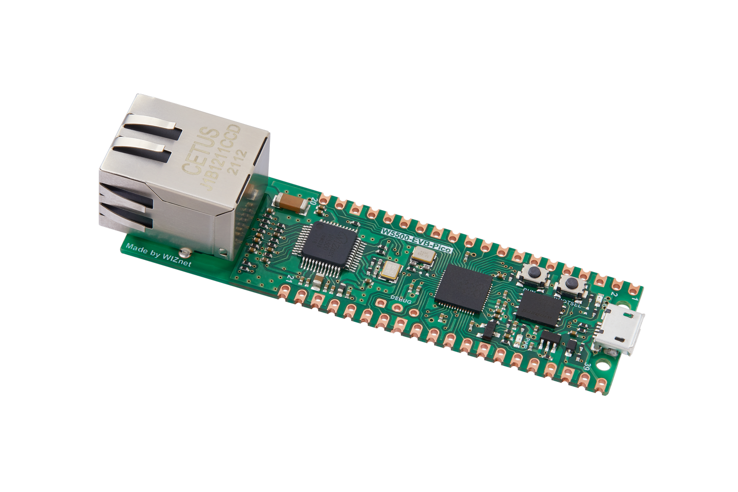
30. W5100S/W5500+RP2040 Raspberry Pi Pico<PPPoE>
30. W5100S/W5500+RP2040 Raspberry Pi Pico<PPPoE>

1 Introduction
PPPoE is a method of transporting Point-to-Point Protocol (PPP) over Ethernet. It is a link layer protocol that encapsulates PPP sessions in Ethernet frames for transmission over Ethernet.
W5100S/W5500 is an embedded Ethernet controller integrating a full hardware TCP/IP protocol stack. It is also an industrial-grade Ethernet control chip. This tutorial will introduce the basic principles, usage steps, application examples and precautions of W5100S/W5500 Ethernet PPPOE application to help readers better master this technology.
2 Protocol Introduction
2.1 What is PPPoE?
PPPoE (Point-to-Point Protocol over Ethernet) is a network tunneling protocol that encapsulates Point-to-Point Protocol (PPP) in an Ethernet framework. It allows the creation of point-to-point tunnels between two Ethernet interfaces in an Ethernet broadcast domain. Since the PPP protocol is integrated into the protocol, it can realize authentication, encryption, compression and other functions that traditional Ethernet cannot provide. It can also be used for Ethernet protocols such as cable modem and digital subscriber line (DSL) to provide users with Access service protocol system.
2.2 Advantages of PPPoE
The advantages of pppoe mainly include:
Convenient for users to use and manage: PPPoE inherits the fast and simple characteristics of Ethernet, and also has the powerful functions of PPP. Users use dial-up network mode, which is convenient and easy to use.
Allow multiple users to share high-speed data access links: PPPoE connects to remote access devices through simple bridge access devices, and can use the sharing of Ethernet to connect to multiple user hosts, allowing multiple users to share a high-speed data access link link.
Dynamic service selection: PPPoE terminal users can access multiple ISPs at the same time. This dynamic service selection function can make it easy for ISPs to create and provide new services.
Strong compatibility: PPPoE is compatible with all existing XDSL Modems and DSLAMs and can be integrated with the existing access structure of ISPs.
Provide independent access control and accounting: PPPoE performs independent access control and accounting for each user, making it convenient for users to use and manage.
2.3 PPPoE data exchange principle
The PPPoE interaction process includes the following steps:
The PPPoE client sends PADI messages through broadcasts to request required services.
After all PPPoE servers within the service range receive the PADI message, they compare the requested service with the service they can provide. If they can provide it, they unicast a PADO message.
The PPPoE client selects an appropriate PADO message among the multiple PADO messages that may be received, and then sends a PPPoE valid discovery request packet (PADR) to the selected access concentrator.
After receiving the PADR message, the access concentrator prepares to start a PPP session. It sends a PPPoE valid discovery session confirmation PADS message. When the host receives the PADS message confirmation, both parties enter the PPP session stage.
2.4 PPPOE application scenarios
PPPoE application scenarios include but are not limited to the following:
Broadband access: PPPoE can be used for various broadband access methods, such as DSL, LAN, HFC, etc., allowing users to connect to the network through the Ethernet interface and achieve a safe, high-speed, and stable Internet experience.
Community network construction: In the community network construction, PPPoE can be used to realize network connection and data transmission within the community, improving network management and security.
Mobile communications: PPPoE can be applied to mobile communications networks to achieve seamless connections and data transmission between different networks, improving network performance and management efficiency.
Remote office and online games: PPPoE can be used to implement functions such as remote office and online games, ensuring the stability and real-time nature of data transmission.
3 WIZnet Ethernet chip
WIZnet mainstream hardware protocol stack Ethernet chip parameter comparison
| Model | Embedded Core | Host I/F | TX/RX Buffer | HW Socket | Network Performance |
|---|---|---|---|---|---|
| W5100S | TCP/IPv4, MAC & PHY | 8bit BUS, SPI | 16KB | 4 | Max.25Mbps |
| W6100 | TCP/IPv4/IPv6, MAC & PHY | 8bit BUS, Fast SPI | 32KB | 8 | Max.25Mbps |
| W5500 | TCP/IPv4, MAC & PHY | Fast SPI | 32KB | 8 | Max 15Mbps |
W5100S/W6100 supports 8-bit data bus interface, and the network transmission speed will be better than W5500.
W6100 supports IPv6 and is compatible with W5100S hardware. If users who already use W5100S need to support IPv6, they can be Pin to Pin compatible.
W5500 has more Sockets and send and receive buffers than W5100S.
4 PPPOE example overview and usage
4.1 Flowchart
The running block diagram of the program is as follows:
4.2 Core preparation work
Software
Visual Studio Code
WIZnet UartTool
Hardware
W5100SIO module + RP2040 Raspberry Pi Pico development board or WIZnet W5100S-EVB-Pico development board
Micro USB interface data cable
TTL to USB
cable
Routers that support dial-up
4.3 Connection method
Connect the USB port of the PC through the data cable (mainly used for burning programs, but can also be used as a virtual serial port)
Convert TTL serial port to USB and connect the default pin of UART0:
RP2040 GPIO0 (UART0 TX) <----> USB_TTL_RX
RP2040 GPIO1 (UART0 RX) <----> USB_TTL_TX
When wiring using module connection RP2040
RP2040 GPIO16 <----> W5100S MISO
RP2040 GPIO17 <----> W5100S CS
RP2040 GPIO18 <----> W5100S SCK
RP2040 GPIO19 <----> W5100S MOSI
RP2040 GPIO20 <----> W5100S RST
Connect the PC and device to the router LAN port through network cables
4.4 Main code overview
We are using the official ioLibrary_Driver library of WIZnet. The library supports rich protocols and is easy to operate. The chip integrates the TCP/IP protocol stack on the hardware. The library also encapsulates the protocols above the TCP/IP layer. We only need to simply call the corresponding function to complete the application of the protocol. .
Step 1: Add the corresponding library file to the pppoe.c file.
Step 2: Define the macros required for PPPOE configuration.
Step 3: Set the ID and password of the PPPOE connection (the ID and password are obtained when setting up the PPPOE user through the router management interface) and the corresponding data length.
Step 4: Configure network information and use static IP mode.
Step 5: The main function first defines a variable to receive the return value of the PPPOE running function, then defines an array to obtain the parameter variables obtained by dialing, then initializes the serial port and SPI, and then writes the network configuration parameters of W5100S , the main loop directly dials PPPOE to determine whether the dialing is successful. If successful, the obtained IP will be printed. If failed, the configured static IP will be printed.
// Use socket
uint8_t gDATABUF[DATA_BUF_SIZE];
uint8_t pppoe_id[6] = "W5100S";
uint8_t pppoe_id_len = 6;
uint8_t pppoe_pw[7] = "WIZnet";
uint8_t pppoe_pw_len = 6;
uint8_t pppoe_ip[4] = {
0,
};
uint16_t pppoe_retry_count = 0;
/* Network information to be configured. */
wiz_NetInfo net_info = {
.mac = {0x00, 0x08, 0xdc, 0x11, 0x22, 0x33}, // Configured MAC address
.ip = {192, 168, 1, 10}, // Configured IP address
.sn = {255, 255, 255, 0}, // Configured subnet mask
.gw = {192, 168, 1, 1}, // Configured gateway
.dns = {8, 8, 8, 8}, // Configured domain address
.dhcp = NETINFO_STATIC}; // Configured dhcp model,NETINFO_DHCP:use dhcp; NETINFO_STATIC: use static ip.
wiz_NetInfo get_info;
int main()
{
int32_t ret = 0;
uint8_t str[15];
struct repeating_timer timer; // Define the timer structure
/* MCU init */
stdio_init_all(); // Initialize the main control peripheral
wizchip_initialize(); // Initialize the chip interface
wizchip_setnetinfo(&net_info); // Configure once first
printf("wiznet chip PPPOE example.\r\n");
while (1)
{
ret = ppp_start(gDATABUF); // ppp start function
if (ret == PPP_SUCCESS || pppoe_retry_count > PPP_MAX_RETRY_COUNT)
{
break; // PPPoE Connected or connect failed by over retry count
}
}
if (ret == PPP_SUCCESS) // 1 : success
{
printf("\r\n<<<< PPPoE Success >>>>\r\n");
printf("Assigned IP address : %d.%d.%d.%d\r\n", pppoe_ip[0], pppoe_ip[1], pppoe_ip[2], pppoe_ip[3]);
printf("\r\n==================================================\r\n");
printf(" AFTER PPPoE, Net Configuration Information \r\n");
printf("==================================================\r\n");
getSHAR(str);
printf("MAC address : %x:%x:%x:%x:%x:%x\r\n", str[0], str[1], str[2], str[3], str[4], str[5]);
getSUBR(str);
printf("SUBNET MASK : %d.%d.%d.%d\r\n", str[0], str[1], str[2], str[3]);
getGAR(str);
printf("G/W IP ADDRESS : %d.%d.%d.%d\r\n", str[0], str[1], str[2], str[3]);
getSIPR(str);
printf("SOURCE IP ADDRESS : %d.%d.%d.%d\r\n\r\n", str[0], str[1], str[2], str[3]);
}
else // failed
{
printf("\r\n<<<< PPPoE Failed >>>>\r\n");
wizchip_setnetinfo(&net_info); // Configuring Network Information
print_network_information(&get_info); // Read back the configuration information and print it
}
while (1)
{
}
}
4.5 Results demonstration
5 Precautions
Note that when using PPPOE for dialing, you must use a router with dialing function, enter the router management interface to enable the PPPOE function, obtain the ID and password, and write them into the code.
If we want to use WIZnet's W5500 to implement the example in this chapter, we only need to modify two places:
(1) Find the wizchip_conf.h header file under library/ioLibrary_Driver/Ethernet/ and modify the WIZCHIP macro definition to W5500.
(2) Find the CMakeLists.txt file under library and set COMPILE_SEL to ON. OFF is W5100S and ON is W5500.
(3) In the macro definition of wol.c file, modify the WIZCHIP macro definition to W5500.


