28. W5100S/W5500+RP2040 Raspberry Pi Pico<MQTT connection to OneNET to control onboard LED>
28. W5100S/W5500+RP2040 Raspberry Pi Pico<MQTT connection to OneNET to control onboard LED>

1. Introduction
The IoT platform provides safe and reliable device connection and communication capabilities, supports device data collection and uploading to the cloud, rule engine data flow, and cloud data delivery to the device. In addition, it also provides convenient and fast device management capabilities, supporting object model definition, structured data storage, and remote debugging, monitoring, and operation and maintenance. This chapter explains how to use the OneNET IoT platform and explains how to use devices to connect to the OneNET IoT platform.
Using W5500 + MQTT application protocol in Ethernet applications allows users to more conveniently implement OneNET remote connection and communication between devices. This tutorial will introduce the application and precautions of W5500 Ethernet MQTT connection to OneNET to help readers better master this technology.
2. Platform Introduction
2.1 初步了解OneNET物联网平台创建产品步骤
How to create products on the OneNET platform:
OneNET website: 中移坤灵 - 中国移动物联网开放平台 (10086.cn)
After entering, log in to your account, then click on the Developer Center in the upper right corner, then click on Create Product under the product development interface, and then select the corresponding parameters.
Click on the product details to add a custom function point in the object model interface
Click Next to record the object model topic in the topic management page of device development.
The functions corresponding to the four topics that need to be recorded here are as shown in the following table:
| Topic Name | Device operation permissions | Effect |
|---|---|---|
| $sys/70TwP2gxl5/{device-name}/thing/property/post | Post | Device reporting properties |
| $sys/70TwP2gxl5/{device-name}/thing/property/post/reply | Subscribe | Cloud reply reporting status |
| $sys/70TwP2gxl5/{device-name}/thing/property/set | Subscribe | Set device properties in the cloud |
| $sys/70TwP2gxl5/{device-name}/thing/property/set_reply | Post | Device reply settings |
Just keep clicking next and then publish the product.
Then add a test device under the device management interface of device access management.
Then record the following parameters:
| Parameter | Value |
|---|---|
| Product ID | 70TwP2gxl5 |
| Equipment name | W5100S_W5500 |
| Device Key | SXFUeWlDUjJqamN4bGNndWRHNmZYc0Eyc2ZTNWh2bWo= |
Generate MQTT connection parameters
The connection address and port number are as shown below:
Other parameters are shown in the figure below:
Calculate password tool:https://open.iot.10086.cn/doc/iot_platform/images/tools/token.exe
After opening, generate the password as shown in the figure below:
2.2 OneNET object model explanation
1.Definition
The object model is a digital abstract description of the device, describing what the device is, what it can do, and what services it can provide to the outside world. The object model digitizes the physical equipment in the physical space and builds the data model of the entity in the cloud, that is, the entity in the physical space is formatted and represented in the cloud.
As shown in the figure above, the object model belongs to the syntax and semantics layer above the application protocol. In the IoT platform, the object model completes the structured definition of terminal product form and product functions, including the format and transmission rules of terminal device business data
The location of the object model function module in the IoT platform is as shown in the figure:
The business logic of the object model belongs to the device management module of the IoT platform. It is used to realize that different devices can be connected to the application platform using a unified physical model standard, and different applications can communicate with each other using a unified physical model standard.
2. Equipment abstract model
The basic functions of the object model are divided into three categories: attributes, services, and events, and the number of function points does not exceed 100.
| Function Type | Explanation |
|---|---|
| Attributes | Used to describe the dynamic characteristics of the device, including the runtime state. Applications can initiate read and set requests for properties. |
| Service | Used to describe the ability of the terminal device to be called externally, and input parameters and output parameters can be set. Services can implement complex business logic, such as performing a specific task; supporting synchronous or asynchronous return of results. |
事件 Translation resultsTranslation resultevent 事件 Translation resultsTranslation resultevent | Uplink messages that can be triggered when the device is running, such as record information of device operation, alarms and fault information issued when the device is abnormal, etc.; can contain multiple output parameters. |
3 WIZnet Ethernet chip
WIZnet mainstream hardware protocol stack Ethernet chip parameter comparison
| Model | Embedded Core | Host I/F | TX/RX Buffer | HW Socket | Network Performance |
|---|---|---|---|---|---|
| W5100S | TCP/IPv4, MAC & PHY | 8bit BUS, SPI | 16KB | 4 | Max.25Mbps |
| W6100 | TCP/IPv4/IPv6, MAC & PHY | 8bit BUS, Fast SPI | 32KB | 8 | Max.25Mbps |
| W5500 | TCP/IPv4, MAC & PHY | Fast SPI | 32KB | 8 | Max 15Mbps |
W5100S/W6100 supports 8-bit data bus interface, and the network transmission speed will be better than W5500.
W6100 supports IPv6 and is compatible with W5100S hardware. If users who already use W5100S need to support IPv6, they can be Pin to Pin compatible.
W5500 has more Sockets and send and receive buffers than W5100S.
4 Example Overview
4.1 Flowchart
The running block diagram of the program is as follows:
4.2 Core preparation work
Software
Visual Studio Code
WIZnet UartTool
OneNET platform
Hardware
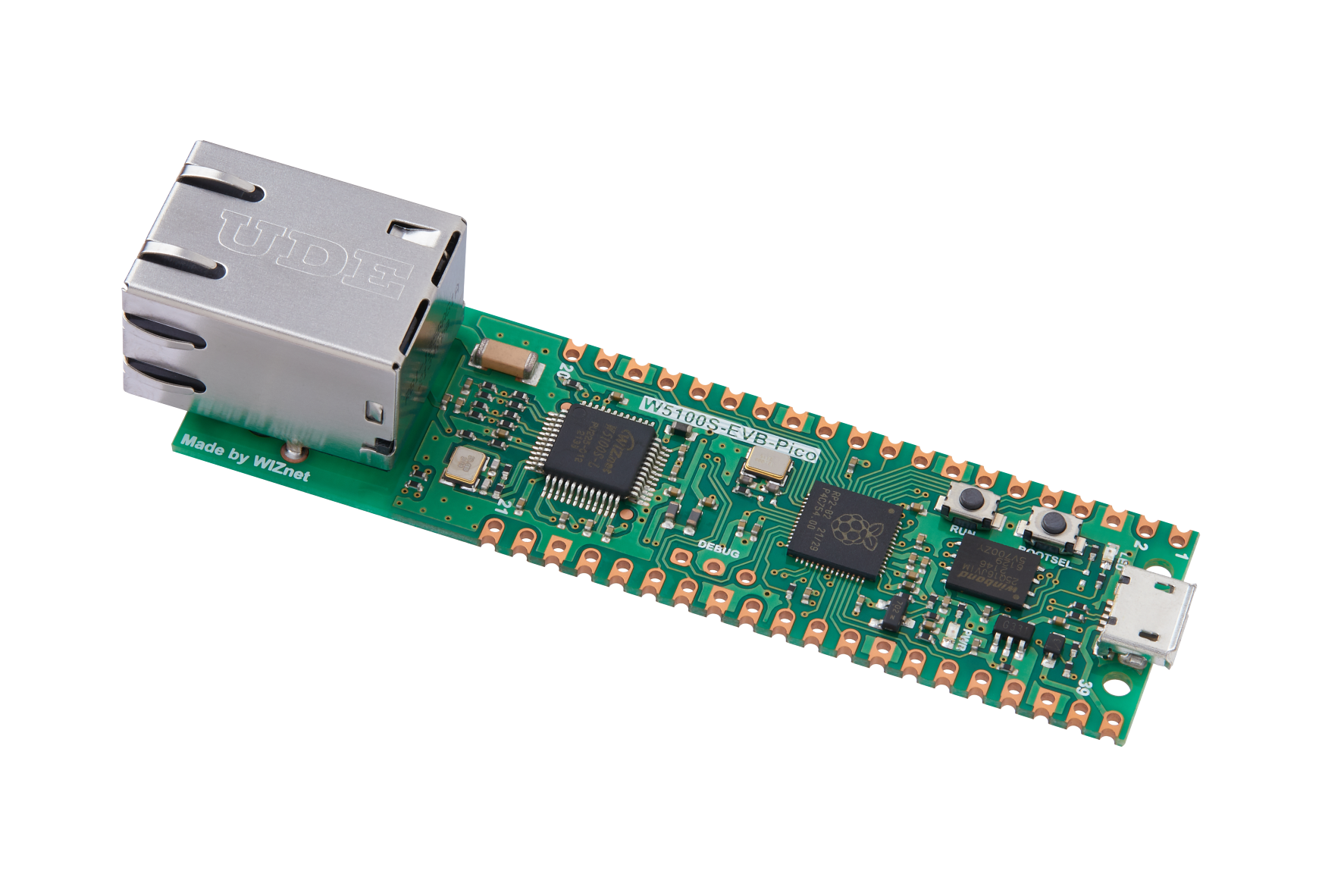
W5100S IO module + RP2040 Raspberry Pi Pico development board or WIZnet W5100S-EVB-Pico development board
Micro USB interface data cable
TTL to USB
cable
4.3 Connection method
Connect the USB port of the PC through the data cable (mainly used for burning programs, but can also be used as a virtual serial port)
Convert TTL serial port to USB and connect the default pin of UART0:
RP2040 GPIO0 (UART0 TX) <----> USB_TTL_RX
RP2040 GPIO1 (UART0 RX) <----> USB_TTL_TX
When wiring using module connection RP2040
RP2040 GPIO16 <----> W5100S MISO
RP2040 GPIO17 <----> W5100S CS
RP2040 GPIO18 <----> W5100S SCK
RP2040 GPIO19 <----> W5100S MOSI
RP2040 GPIO20 <----> W5100S RST
Connect the PC and device to the router LAN port through network cables
4.4 Main code overview
We are using the official ioLibrary_Driver library of WIZnet. The library supports rich protocols and is easy to operate. The chip integrates the TCP/IP protocol stack on the hardware. The library also encapsulates the protocols above the TCP/IP layer. We only need to simply call the corresponding function to complete the application of the protocol. .
Step 1: Reference the corresponding library in the mqtt_onenet.c file.
Step 2: Macro definition related content
Step 3: Define a structure of mqtt connection parameters and define it. The value assigned to the structure here is to connect the parameters corresponding to OneNET and the subscription and publishing topic of the object model.
Step 4: Set the default IP address information and flags.
Step 5: Write several functions, including network initialization function, 1 second timer callback function, 1 millisecond timer callback function, MQTT initialization function, MQTT message receiving callback function, DNS parsing function and json parsing function.
Step 6: Write the timer callback processing function for DHCP and MQTT tick timer processing functions.
Step 7: The main function first initializes the serial port and SPI, and then writes the network configuration parameters of W5100S. After initializing DHCP, it starts DHCP to obtain the IP. When obtained, it prints the obtained IP. When the number of acquisitions exceeds the maximum number of acquisitions, static is used. IP and DNS resolve domain names, and then initialize MQTT. Then the main loop is a state machine polling, which will connect, subscribe, regularly report messages, keep alive, and receive messages according to the flow chart.
The main function code is as follows:
int main()
{
/* Variable definition */
int ret;
struct repeating_timer timer_1s;
struct repeating_timer timer_1ms;
uint8_t pubmsg[128] = {0};
/*mcu init*/
stdio_init_all(); /*Initialize the serial port*/
wizchip_initialize(); /*Initialize the SPI*/
/* LED init */
gpio_init(LED_PIN);
gpio_set_dir(LED_PIN, GPIO_OUT);
/*timer init*/
add_repeating_timer_ms(1000, repeating_timer_1s_callback, NULL, &timer_1s); // Add DHCP and DNS 1s Tick Timer handler
add_repeating_timer_ms(1, repeating_timer_1ms_callback, NULL, &timer_1ms); // Add MQTT 1ms Tick Timer handler
/*dhcp init*/
DHCP_init(SOCK_DHCP, ethernet_buf); // DHCP initialization
/*dns init*/
DNS_init(SOCK_DNS, ethernet_buf);
/* Set the network address information */
printf("wiznet chip mqtt of onenet example.\r\n");
network_init(&net_info); // Configuring Network Information
print_network_information(&get_info); // Read back the configuration information and print it
/* Resolve mqtt broker domain names using dns */
do_dns(mqtt_params.mqttHostUrl, mqtt_params.server_ip);
/*mqtt init*/
mqtt_init();
while (true)
{
switch (run_status)
{
case CONN:
{
ret = MQTTConnect(&c, &data); /* Connect to the MQTT server */
printf("Connect to the MQTT server: %d.%d.%d.%d:%d\r\n", mqtt_params.server_ip[0], mqtt_params.server_ip[1], mqtt_params.server_ip[2], mqtt_params.server_ip[3], mqtt_params.port);
printf("Connected:%s\r\n\r\n", ret == SUCCESSS ? "success" : "failed");
if (ret != SUCCESSS)
{
run_status = ERROR;
}
else
{
run_status = SUB;
}
break;
}
case SUB:
{
ret = MQTTSubscribe(&c, mqtt_params.subtopic, mqtt_params.subQoS, messageArrived); /* Subscribe to Topics */
printf("Subscribing to %s\r\n", mqtt_params.subtopic);
printf("Subscribed:%s\r\n\r\n", ret == SUCCESSS ? "success" : "failed");
if (ret != SUCCESSS)
{
run_status = ERROR;
}
else
{
run_status = KEEPALIVE;
}
ret = MQTTSubscribe(&c, mqtt_params.pubtopic_reply, mqtt_params.subQoS, NULL); /* Subscribe to Topics */
printf("Subscribing to %s\r\n", mqtt_params.pubtopic_reply);
printf("Subscribed:%s\r\n\r\n", ret == SUCCESSS ? "success" : "failed");
if (ret != SUCCESSS)
{
run_status = ERROR;
}
else
{
run_status = KEEPALIVE;
}
break;
}
case PUB:
{
if (pub_time >= 5)
{
pub_time = 0;
sprintf(pubmsg, "{\"id\": \"123\",\"version\": \"1.0\",\"params\": {\"LEDSwitch\": {\"value\":%s}}}", gpio_get(LED_PIN) == ON ? "true" : "false");
pubmessage.payload = pubmsg;
pubmessage.payloadlen = strlen(pubmessage.payload);
ret = MQTTPublish(&c, mqtt_params.pubtopic, &pubmessage); /* Publish message */
if (ret != SUCCESSS)
{
run_status = ERROR;
}
else
{
printf("publish:%s,%s\r\n\r\n", mqtt_params.pubtopic, pubmessage.payload);
}
}
else
{
run_status = KEEPALIVE;
}
break;
}
case KEEPALIVE:
{
if (MQTTYield(&c, 30) != SUCCESSS) /* keepalive MQTT */
{
run_status = ERROR;
}
else
{
run_status = PUB;
}
sleep_ms(100);
break;
}
case ERROR: /* Running error */
printf("system ERROR!\r\n");
sleep_ms(1000);
break;
default:
break;
}
}
}4.5 Results demonstration
1. Open WIZ UartTool, fill in the parameters, obtain the IP, parse the mqtt server domain name, and then connect to OneNET. After the connection is successful, the subscribed topic will be printed, and the onboard LED light status will be reported to the server regularly.
2. Send instructions through OneNET to control the LED to turn on
3. The platform object model can also receive the onboard LED light status on the device.
5 Precautions
Don't make a mistake in subscribing and publishing object model topics, otherwise it will cause failure to operate properly.
When copying the OneNET object model theme, you need to replace {device-name} with the device name.
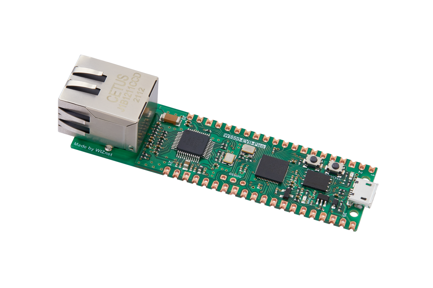
If we want to use WIZnet's W5500 to implement the example in this chapter, we only need to modify two places:
(1) Find the wizchip_conf.h header file under library/ioLibrary_Driver/Ethernet/ and modify the WIZCHIP macro definition to W5500.
(2) Find the CMakeLists.txt file under library and set COMPILE_SEL to ON. OFF is W5100S and ON is W5500.


