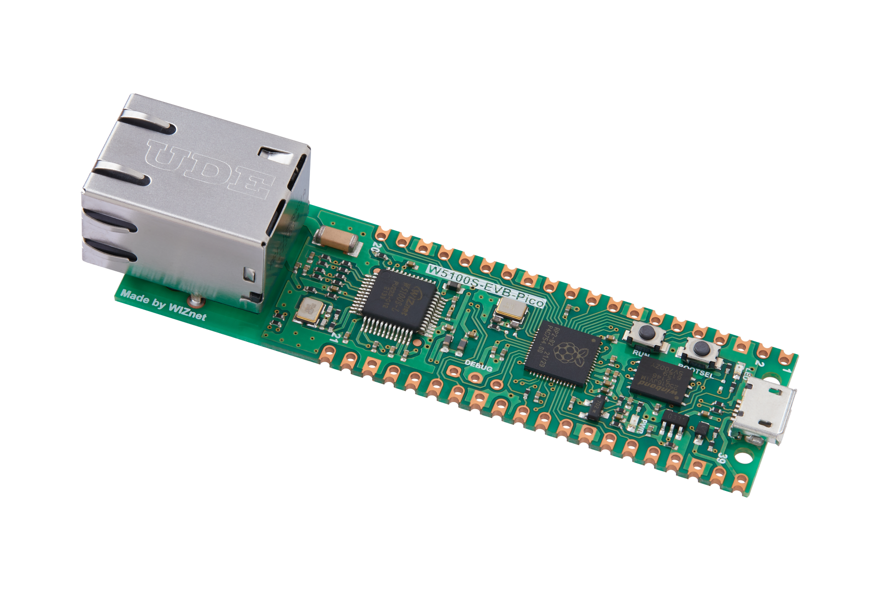
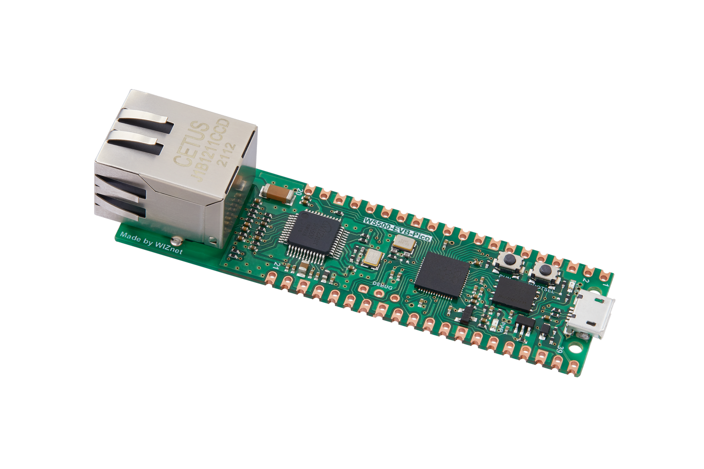
26. W5100S/W5500+RP2040 Raspberry Pi Pico<WOL Example>
26. W5100S/W5500+RP2040 Raspberry Pi Pico<WOL Example>

1 Introduction
Wake on LAN technology combines smart contracts and blockchain technology, which makes transactions safer, faster and more transparent. At the same time, Wake on LAN implements a distributed consensus algorithm, which allows large-scale transactions to maintain efficiency and stability.
W5100S/W5500 is an embedded Ethernet controller integrating a full hardware TCP/IP protocol stack. It is also an industrial-grade Ethernet control chip. This tutorial will introduce the basic principles, usage steps, application examples and precautions of W5100S/W5500 Ethernet WOL application to help readers better master this technology.
2 Technology Introduction
2.1 What is Wake on LAN?
"Wake on LAN" (WOL for short) is a computer network remote startup technology that allows a powered-off computer to be woken up remotely via the Internet or LAN. This technology is mainly used in remote management, telecommuting, home automation and other fields.
2.2 Advantages of Wake on LAN
The features of Wake on LAN mainly include the following aspects:
Remote boot: Wake on LAN allows users to boot their computer from a remote location without having to physically operate the computer.
Energy Saving and Environmental Protection: By starting your computer remotely, you can save energy and reduce carbon emissions.
Convenient and fast: Wake on LAN technology is simple and easy to use, requiring no cumbersome settings and operations.
High security: Remotely starting a computer requires specific data packets and matching parameters, so security is high.
Widely applicable: Wake on LAN is suitable for homes, offices, data centers and other places, as well as computer rental, server management and other scenarios.
2.3 Wake on LAN data exchange principle
The principle steps of Wake on LAN (remotely starting a LAN computer) are as follows:
The sending end (user end) sends a "wake-up packet" (Magic Packet, or "magic packet") through software or hardware (such as a network card). The destination address of the packet is the MAC address of the computer that needs to be awakened.
A wake-up packet is a broadcast frame that contains the MAC address of the target computer. Due to the uniqueness of the MAC address, the data packet can be uniquely identified in the network.
When the target computer receives this wake-up packet, it will check the MAC address and password information. If this information matches the values preset in the computer, the computer will wake up from the shutdown state and start the boot (BootLoader) or running state.
2.4 Wake on LAN application scenario
Wake on LAN (remotely start LAN computers) technology can be applied to a variety of scenarios. The following are some common application scenarios:
Remote working: Through WOL technology, users can remotely start the company or office computer at home or other locations, thereby achieving home working or remote working.
Server management: Server administrators can use WOL technology to remotely start and manage servers for software installation, system updates, or other maintenance tasks.
Home automation: By connecting the computer at home to other smart devices and using WOL technology, users can remotely control other devices at home, such as turning on lights, adjusting temperature, etc.
Multimedia applications: WOL technology can be used to remotely start media players or other devices to remotely play video, audio or other multimedia content.
Network monitoring: Using WOL technology, network cameras or other monitoring equipment can be remotely activated for security monitoring or remote inspection.
Smart home: Similar to home automation, WOL technology can also be used in the smart home field, such as remote control of home appliances, lighting, curtains and other equipment.
3 WIZnet Ethernet chip
WIZnet mainstream hardware protocol stack Ethernet chip parameter comparison
| Model | Embedded Core | Host I/F | TX/RX Buffer | HW Socket | Network Performance |
|---|---|---|---|---|---|
| W5100S | TCP/IPv4, MAC & PHY | 8bit BUS, SPI | 16KB | 4 | Max.25Mbps |
| W6100 | TCP/IPv4/IPv6, MAC & PHY | 8bit BUS, Fast SPI | 32KB | 8 | Max.25Mbps |
| W5500 | TCP/IPv4, MAC & PHY | Fast SPI | 32KB | 8 | Max 15Mbps |
W5100S/W6100 supports 8-bit data bus interface, and the network transmission speed will be better than W5500.
W6100 supports IPv6 and is compatible with W5100S hardware. If users who already use W5100S need to support IPv6, they can be Pin to Pin compatible.
W5500 has more Sockets and send and receive buffers than W5100S.
4 Wake on LAN example overview and usage
4.1 Flowchart
The running block diagram of the program is as follows:
4.2 Core preparation work
Software
Visual Studio Code
WIZnet UartTool
NetAssist
Hardware
W5100SIO module + RP2040 Raspberry Pi Pico development board or WIZnet W5100S-EVB-Pico development board
Micro USB interface data cable
TTL to USB
cable
4.3 Connection method
Connect the USB port of the PC through the data cable (mainly used for burning programs, but can also be used as a virtual serial port)
Convert TTL serial port to USB and connect the default pin of UART0:
RP2040 GPIO0 (UART0 TX) <----> USB_TTL_RX
RP2040 GPIO1 (UART0 RX) <----> USB_TTL_TX
When wiring using module connection RP2040
RP2040 GPIO16 <----> W5100S MISO
RP2040 GPIO17 <----> W5100S CS
RP2040 GPIO18 <----> W5100S SCK
RP2040 GPIO19 <----> W5100S MOSI
RP2040 GPIO20 <----> W5100S RST
Connect the PC and device to the router LAN port through network cables
4.4 Main code overview
We are using the official ioLibrary_Driver library of WIZnet. The library supports rich protocols and is easy to operate. The chip integrates the TCP/IP protocol stack on the hardware. The library also encapsulates the protocols above the TCP/IP layer. We only need to simply call the corresponding function to complete the application of the protocol. .
Step 1: Add the corresponding library file to the wol.c file.
Step 2: Define the macros required for DHCP configuration.
Step 3: Configure network information and turn on DHCP mode.
Step 4: Write a timer callback processing function for the DHCP 1 second tick timer processing function.
Step 5: The main function first defines a timer structure parameter to trigger the timer callback function, initializes the serial port and SPI, then writes the network configuration parameters of W5100S, initializes DHCP and starts DHCP to obtain the IP. Print the obtained IP. When the number of acquisitions exceeds the maximum number of acquisitions, a static IP will be used. A Switch state machine in the main loop polls the socket status, connects to the remote device, and then sends and receives data to determine whether the received packet is a magic packet. If it is a magic packet, it will enter the interrupt and wake up the device.
// W5100S,W5500
/**< Wake on Lan */
/**< Wake on Lan */
// DHCP retry times
wiz_NetInfo net_info = {
.mac = {0x00, 0x08, 0xdc, 0x16, 0xed, 0x2f}, // Define MAC variables
.ip = {192, 168, 1, 10}, // Define IP variables
.sn = {255, 255, 255, 0}, // Define subnet variables
.gw = {192, 168, 1, 1}, // Define gateway variables
.dns = {8, 8, 8, 8}, // Define DNS variables
.dhcp = NETINFO_DHCP}; // Define the DNCP mode
wiz_NetInfo get_info;
static uint8_t ethernet_buf[ETHERNET_BUF_MAX_SIZE] = {
0,
};
uint8_t buffer[2048];
uint8_t rIP[4];
uint16_t rPort = 8000;
uint8_t DIP[4] = {192, 168, 1, 18};
static uint8_t dhcp_get_ip_flag = 0; // Define the DHCP acquisition flag
uint16_t DPORT = 8000;
/**
* @brief Timer callback processing function, used for dhcp timing processing
* @param repeating :Timer structure
* @return bool
*/
bool repeating_timer_callback_DHCP(struct repeating_timer *t);
/**
* @brief Initialization of chip network information
* @param conf_info :Static configuration information
* @return none
*/
void network_init(wiz_NetInfo *conf_info);
int main()
{
struct repeating_timer timer; // Define the timer structure
struct repeating_timer timer1; // Define the timer structure
uint8_t dns_retry_cnt = 0; // Number of parsings
uint8_t dns_ok = 0; // Parse success Peugeot
uint16_t len = 0;
/*mcu init*/
stdio_init_all(); // Initialize the main control periphera
wizchip_initialize(); // spi initialization
wizchip_setnetinfo(&net_info); // Configure once first
/*dhcp init*/
DHCP_init(SOCKET_ID, ethernet_buf); // DHCP initialization
add_repeating_timer_ms(1000, repeating_timer_callback_DHCP, NULL, &timer); // Add DHCP 1s Tick Timer handler
printf("wiznet chip Wake On Lan client example.\r\n");
network_init(&net_info); // Configuring Network Information
print_network_information(&get_info); // Read back the configuration information and print it
while (true)
{
switch (getSn_SR(0))
{
case SOCK_UDP:
if (getSn_IR(0) & Sn_IR_RECV)
{
setSn_IR(0, Sn_IR_RECV);
}
if (getIR2() & 0x01) // Received WOL Magic packet based on UDP.
{
printf("get wake on line\r\n");
setIR2(0x01);
}
if ((len = getSn_RX_RSR(0)) > 0) // Determine if a message has been received
{
recvfrom(0, buffer, len, DIP, &rPort); // Receive Data
printf("%s", buffer);
sendto(0, buffer, len, DIP, DPORT); // Send Data
}
break;
case SOCK_CLOSED:
socket(0, Sn_MR_UDP, 9000, 0);
setIMR2(0x01); // Open WOL magic pack interrupt
setMR2(W5100S_WOL); // Receive WOL packets
break;
}
}
while (true)
{
switch (getSn_SR(0))
{
case SOCK_UDP:
if (getSn_IR(0) & Sn_IR_RECV)
{
setSn_IR(0, Sn_IR_RECV);
}
if (getIR() & 0x10) // Received WOL Magic packet based on UDP.
{
printf("get wake on line\r\n");
setIR(0x10);
}
if ((len = getSn_RX_RSR(0)) > 0) // Determine if a message has been received
{
recvfrom(0, buffer, len, DIP, &rPort); // Receive Data
printf("%s", buffer);
sendto(0, buffer, len, DIP, DPORT); // Send Data
}
break;
case SOCK_CLOSED:
socket(0, Sn_MR_UDP, 9000, 0);
setIMR(0x10); // Open WOL magic pack interrupt
setMR(W5500_WOL); // Receive WOL packets
break;
}
}
}4.5 Results demonstration
1. After the code is compiled and burned, open the WIZnet UartTool serial port debugging tool, fill in the parameters, and press reset to display the network configuration information of the development board.
2. Then open the network debugging tool in udp mode and connect to the IP obtained by the development board. The port number is 9000 and enter "magic packet" in the sending box. The format of the "magic packet" is ffffffffffff+16 times the MAC address of W5100S, and the number of bytes is 102.
3. After receiving the correct "magic packet", the WIZnet UartTool serial port debugging tool will print a message telling you that the "magic packet" has been obtained and respond.
5 Precautions
The format of the "mode packet" must be ffffffffffff+16 times the Ethernet MAC address, otherwise the "magic packet" will be unreachable.
If we want to use WIZnet's W5500 to implement the example in this chapter, we only need to modify two places:
(1) Find the wizchip_conf.h header file under library/ioLibrary_Driver/Ethernet/ and modify the WIZCHIP macro definition to W5500.
(2) Find the CMakeLists.txt file under library and set COMPILE_SEL to ON. OFF is W5100S and ON is W5500.
(3) In the macro definition of wol.c file, modify the WIZCHIP macro definition to W5500.


