21. W5100S/W5500+RP2040 Raspberry Pi Pico<Host computer search and configuration device>
21. W5100S/W5500+RP2040 Raspberry Pi Pico<Host computer search and configuration device>

1 Introduction
In the field of automation and control systems, the upper computer and the lower computer are the core components. The upper computer is responsible for issuing control commands and monitoring the system status, while the lower computer is responsible for receiving these commands and directly controlling the equipment. Through the collaborative work of the upper computer and lower computer, various complex automation and control system functions can be realized.
This chapter will use W5100S/W5500 + Raspberry Pi RP2040 to search for devices and configure devices on the host computer.
W5100S/W5500 is an embedded Ethernet controller integrating a full hardware TCP/IP protocol stack. It is also an industrial-grade Ethernet control chip. Using the W5100S/W5500 in Ethernet applications makes it easier for users to connect and communicate remotely between devices.
2. Protocol introduction
2.1 Brief description
Host computer and slave computer are concepts often used in the field of automation and control systems. Simply put, the upper computer refers to a computer or computer system that can issue control commands and monitor system status, while the lower computer is a computer or computer system that is responsible for receiving control commands from the upper computer and directly controlling the equipment.
The host computer usually has higher-level control and management functions and can run complex applications independently. It can also connect multiple slave computers to monitor, control and process data. In a distributed system, the host computer usually runs on a powerful computer or server and provides a user-friendly graphical interface so that users can interact with the system.
The lower computer usually runs in a low-level computer or embedded system and is responsible for performing simple control tasks, collecting sensor data and transmitting it to the upper computer, or executing instructions sent by the upper computer. The lower computer usually uses programs written in low-level languages and can directly interact with the hardware. In many distributed systems, the lower computer communicates with the upper computer through communication protocols so that the upper computer can remotely control and monitor the lower computer and obtain real-time data and status information from the lower computer.
In fields such as industrial automation and the Internet of Things, host computers and slave computers are often used together to achieve functions such as control, acquisition, processing, and storage. Through the collaborative work of the upper computer and lower computer, various complex automation and control system functions can be realized.
2.2 Principle
Search: The upper computer sends the FIND command through UDP broadcast, and the device, as a lower computer, sends its own configuration information to the upper computer after receiving it. After receiving it, the upper computer presents the obtained device information;
Configuration: After the device has been searched, after the host computer sends a SETT command to the device, the device will reconfigure the local device based on the network information displayed by the host computer and display it on the serial port.
2.3 Advantages
Efficiency: Configuring the upper computer with the lower computer can greatly improve the efficiency of the control system. The upper computer issues control commands, and the lower computer receives and interprets them into corresponding timing signals to directly control the equipment. The response speed is fast and the reliability is high.
Real-time: The lower computer can respond to the control instructions of the upper computer in real time and control the equipment in real time to ensure the stability and safety of the system. At the same time, the lower computer can also feed back equipment status data to the upper computer in real time, so that the upper computer can understand the system status in time and make corresponding control adjustments.
High reliability: The lower computer usually has its own operating system and programming language, which can adapt to various hardware platforms and system architectures to facilitate system expansion and maintenance. In addition, the lower computer can also directly control the equipment and obtain equipment status data, with high reliability.
Flexibility: The upper computer and lower computer can be flexibly combined and expanded to meet the needs of different systems. The upper computer can connect to multiple lower computers at the same time to monitor, control and process data on them. At the same time, the lower computer can also connect multiple devices as needed to achieve distributed control of the equipment.
Maintainability: The upper computer and the lower computer have their own development systems and programming languages to facilitate system development and maintenance. At the same time, the upper computer and lower computer can also be remotely monitored and maintained to improve the maintainability of the system.
In short, the advantages of configuring the upper computer with the lower computer mainly include high efficiency, real-time performance, high reliability, flexibility and maintainability. These advantages make the upper computer and lower computer widely used in automation and control systems.
2.4 Application
Automated industry:
The upper computer issues control instructions, and the lower computer receives and interprets them into corresponding timing signals to directly control the equipment. The response speed is fast and the reliability is high.
The host computer can monitor the production process, issue control instructions, perform data analysis and optimization, etc.
The lower computer can control the equipment in real time, collect equipment status data, receive and execute control instructions, etc.
Internet of Things:
The host computer can remotely monitor and manage equipment, perform data analysis and processing, etc.
The lower computer can receive and execute control instructions, collect and transmit equipment status data, etc.
Smart home:
The host computer can issue control instructions, monitor home networks, etc.
The lower computer can receive and execute control instructions, control the operation and status collection of intelligent equipment, etc.
Medical equipment:
The host computer can issue control instructions, remotely monitor and manage medical equipment, etc.
The lower computer can receive and execute control instructions, control the operation and status collection of medical equipment, etc.
Vehicle electronics:
The host computer can issue control instructions, monitor vehicle status, etc.
The lower computer can receive and execute control instructions, control the operation and status collection of various vehicle systems, etc.
In these applications, the upper computer and lower computer realize various complex automation and control system functions through division of labor and cooperation, improving production efficiency and management level.
3. WIZnet Ethernet chip
WIZnet mainstream hardware protocol stack Ethernet chip parameter comparison
| Model | Embedded Core | Host I/F | TX/RX Buffer | HW Socket | Network Performance |
|---|---|---|---|---|---|
| W5100S | TCP/IPv4, MAC & PHY | 8 bit BUS, SPI | 16 KB | 4 | Max 25 Mbps |
| W6100 | TCP/IPv4/IPv6, MAC & PHY | 8 bit BUS, Fast SPI | 32 KB | 8 | Max 25 Mbps |
| W5500 | TCP/IPv4, MAC & PHY | Fast SPI | 32 KB | 8 | Max 15 Mbps |
W5100S/W6100 supports 8-bit data bus interface, and the network transmission speed will be better than W5500.
W6100 supports IPv6 and is Pin to Pin compatible with W5100S. If users who already use W5100S need to support IPv6, they can directly switch to it.
W5500 has more sockets and send and receive buffers than W5100S
4. Host computer search and configuration test
4.1 Program flow chart
4.2 Test preparation
Software:
Visual Studio Code
WIZnet UartTool
Smart ConfigTool
Hardware
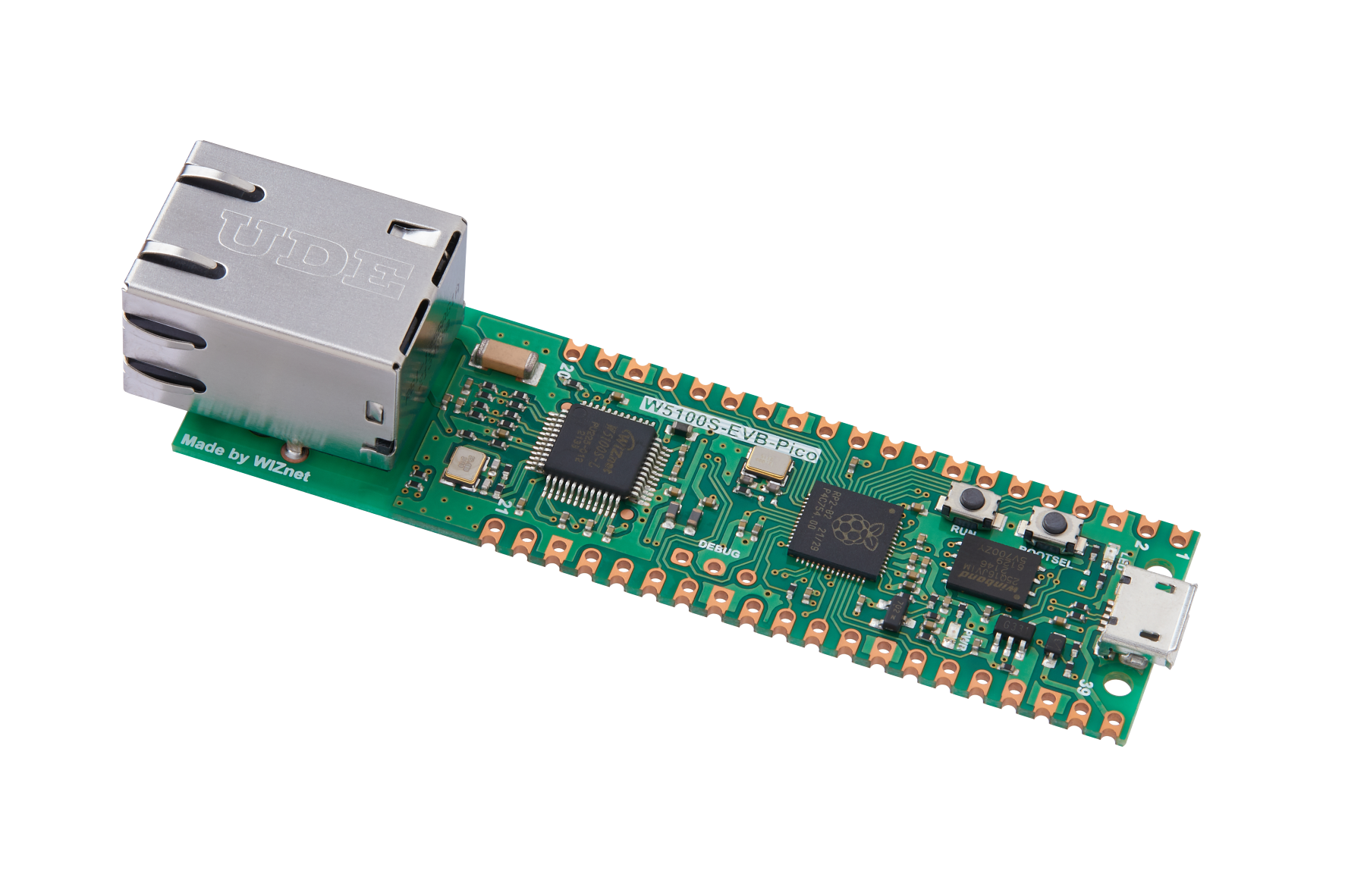
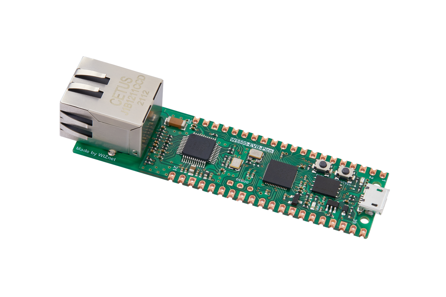
W5100SIO module + RP2040 Raspberry Pi Pico development board or WIZnet W5100S-EVB-Pico development board
Micro USB interface data cable
TTL to USB
cable
4.3 Connection method
Connect the USB port of the PC through the data cable (mainly used for burning programs, but can also be used as a virtual serial port)
Convert TTL serial port to USB and connect the default pin of UART0:
RP2040 GPIO 0 (UART0 TX) <----> USB_TTL_RX
RP2040 GPIO 1 (UART0 RX) <----> USB_TTL_TX
When using the module to connect RP2040 for wiring
RP2040 GPIO 16 <----> W5100S MISO
RP2040 GPIO 17 <----> W5100S CS
RP2040 GPIO 18 <----> W5100S SCK
RP2040 GPIO 19 <----> W5100S MOSI
RP2040 GPIO 20 <----> W5100S RST
Directly connect to the PC network port through a network cable (or: both the PC and the device are connected to the switch or router LAN port through a network cable)
4.4 Related code
Open the upper_computer_search.c file (path: examples/upper_computer_search/upper_computer_search.c) to see the specific implementation:
You can see that the network information is configured in dhcp mode. Therefore, after the master control and W5100S are initialized, DHCP initialization will be performed, and then a timer initialization will be added for timing during the dhcp process for timeout processing; then enter dhcp configures the network information. If it succeeds, it will directly enter the loop to call the loopback test function. If it fails, it will use the static network information we initialized to configure, and then enter the while loop to run the do_udp_config function, as shown below:
/* Network information to be configured. */
wiz_NetInfo net_info = {
.mac = {0x00, 0x08, 0xdc, 0x1e, 0xed, 0x2e}, // Configured MAC address
.ip = {192, 168, 1, 10}, // Configured IP address
.sn = {255, 255, 255, 0}, // Configured subnet mask
.gw = {192, 168, 1, 1}, // Configured gateway
.dns = {8, 8, 8, 8}, // Configured domain address
.dhcp = NETINFO_DHCP}; // Configured dhcp model,NETINFO_DHCP:use dhcp; NETINFO_STATIC: use static ip.
static uint8_t ethernet_buf[ETHERNET_BUF_MAX_SIZE] = {
0,
}; // Send and receive cachestatic
static uint8_t destip[4] = {183, 230, 40, 34}; // OneNET HTTP access IP
static uint16_t destport = 80; // OneNET HTTP access port
static uint8_t breakout_flag = 0; // Define the DHCP acquisition flag
int main()
{
struct repeating_timer timer; // Define the timer structure
wiz_NetInfo get_info; // Stores the read configuration information
/* MCU init */
stdio_init_all(); // Initialize the main control peripheral
wizchip_initialize(); // Initialize the chip interface
/*dhcp init*/
DHCP_init(SOCKET_ID, ethernet_buf); // DHCP initialization
add_repeating_timer_ms(1000, repeating_timer_callback, NULL, &timer); // Add DHCP 1s Tick Timer handler
printf("wiznet chip UpperComputer Search example.\r\n");
network_init(&net_info); // Configuring Network Information
print_network_information(&get_info); // Read back the configuration information and print it
while (true)
{
do_udp_config(SOCKET_ID); // Run and precess UpperComputer command.
}
}The do_udp_config function needs to pass in a socket port number, because the interaction between the upper computer and the lower computer is implemented through udp. Inside the function, the Switch state machine is used to poll the socket status, run udp mode and interact with the upper computer, as shown below:
/**
* @brief Run receive UpperComputer command and precess.
* @param sn: socket number
* @return none.
*/
void do_udp_config(uint8_t sn)
{
uint16_t i;
uint16_t len;
uint8_t rip[4];
uint16_t rport;
uint8_t bip[4] = {255, 255, 255, 255};
uint16_t local_port = 1460;
uint8_t sw_version[2] = {1, 0};
memset(RecvMsg.op, 0, sizeof(RecvMsg)); // clear RecvMsg
switch (getSn_SR(sn))
{
case SOCK_UDP:
if ((len = getSn_RX_RSR(sn)) > 0)
{
recvfrom(sn, (uint8_t *)&RecvMsg, len, rip, &rport);
// FIND: searching, SETT: setting, FIRM: firmware uploading
if ((RecvMsg.op[0] == 'F') && (RecvMsg.op[1] == 'I') && (RecvMsg.op[2] == 'N') && (RecvMsg.op[3] == 'D'))
{
wizchip_getnetinfo(&netinfo); // get config network infomation.
for (i = 0; i < 6; i++)
{
ConfigMsg.mac[i] = netinfo.mac[i];
if (i < 4)
{
ConfigMsg.lip[i] = netinfo.ip[i];
ConfigMsg.gw[i] = netinfo.gw[i];
ConfigMsg.dns[i] = netinfo.dns[i];
ConfigMsg.sub[i] = netinfo.sn[i];
}
if (i < 2)
{
ConfigMsg.sw_ver[i] = sw_version[i];
}
}
RecvMsg = ConfigMsg;
RecvMsg.op[0] = 'F';
RecvMsg.op[1] = 'I';
RecvMsg.op[2] = 'N';
RecvMsg.op[3] = 'D';
sendto(sn, (uint8_t *)&RecvMsg, sizeof(RecvMsg), bip, rport); // return network info to uppercomputer.
printf("Find\r\n");
}
else if ((RecvMsg.op[0] == 'S') && (RecvMsg.op[1] == 'E') && (RecvMsg.op[2] == 'T') && (RecvMsg.op[3] == 'T'))
{
printf("Seet\r\n");
if ((RecvMsg.mac[0] == ConfigMsg.mac[0]) && (RecvMsg.mac[1] == ConfigMsg.mac[1]) && (RecvMsg.mac[2] == ConfigMsg.mac[2]) &&
(RecvMsg.mac[3] == ConfigMsg.mac[3]) && (RecvMsg.mac[4] == ConfigMsg.mac[4]) && (RecvMsg.mac[5] == ConfigMsg.mac[5]))
{
for (i = 0; i < 4; i++) // recv uppercomputer config network info
{
netinfo.ip[i] = RecvMsg.lip[i];
netinfo.sn[i] = RecvMsg.sub[i];
netinfo.gw[i] = RecvMsg.gw[i];
netinfo.dns[i] = RecvMsg.dns[i];
netinfo.dhcp = NETINFO_STATIC;
}
wizchip_setnetinfo(&netinfo); // write chip
printf("From the UpperComputer Config network information :\r\n");
print_network_information(&netinfo); // readback and print
}
}
}
break;
case SOCK_CLOSED:
socket(sn, Sn_MR_UDP, local_port, 0x00);
break;
}
}4.5 Test Result
After the hardware connection is correct, compile the burning program, open WIZ UartTool, select the corresponding COM port, and fill in the parameters: baud rate 115200, 8 data bits, 1 stop bit, no parity bit, no flow control, complete After setting the parameters, click open to open, and observe the information printed by the serial port to obtain the device running status; after waiting for the device to print relevant network information, open the ConfigTool host tool, click Search to see that the host computer successfully obtains and presents the device information, and then modify the IP address. Click Setting to see that the network information after the host computer is configured is printed on the serial port, as shown in the figure below:
5. Precautions
Note that the configuration operation can only be performed after the upper computer searches and finds the lower computer equipment.
If we want to use WIZnet's W5500 to implement the example in this chapter, we only need to modify two places:
Find the wizchip_conf.h header file under library/ioLibrary_Driver/Ethernet/ and modify the WIZCHIP macro definition to W5500.
Find the CMakeLists.txt file under the library and set COMPILE_SEL to ON. OFF is W5100S and ON is W5500.


