Single Processor Environmental Sensor Cloud Logger
Device will read temperature and humidity from directly connected sensor and transmit measured data to the cloud for later visualisation.

Software Apps and online services
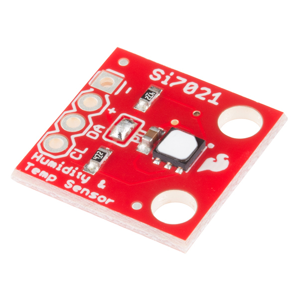
Hello everyone. This article contains description of my projects which I implemented as part of WIZnet WizFi360 Design Contest. Article contains also my thoughts and opinions about whole ecosystem, so it can be suitable if you considering WizFi360 and want to know more about it. I was new to this platform and this competition gave me opportunity to play with it. I am very enthusiastic in digital electronics, and I love learning chips at as low as possible level. For this reason, I spend about two months of learning all WizFi360 possibilities which later resulted to solution with very interesting properties. As part of competition, I pointed mostly WizFi360 Wi-Fi module and did not spend very much time with other peripherals, thus I used simple HTU21D temperature and sensor as a source of data for sending to the cloud. Main goal of my project was to develop firmware for WizFi360 module CPU which will not only connect my device to the internet, but also handle communication with sensors directly connected to it. Goal was to do not require having any other microcontroller in the system. Thus, this design resulted to reduced power consumption (less chips), better cost (less chips), physical dimension (less PCB occupied) and reduced need for developing and maintaining multiple firmwares.
Board Selection
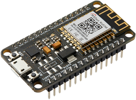
Because I wanted to examine WizFi360 as much as possible I chosen module which expose all its pins. This kicked out from game very interesting WizFi360-EVB-Pico because this boards exposes pins of RP2040 MCU and not the WizFi360 module which I was mostly interested in. Similarly, I want to examine the module and do not face issues with custom PCB design, so I decided to choose WizFi360-EVB-Mini. I would like to thank Wiznet for sending me free sample of this board.
After I received board I soldered pinheads to it, so I was able to use it on breadboard. Dimensions of board leave one row of pins free on standard breadboard, so you can kindly use single breadboard and both rows of pins.
Experimenting with AT commands
Board have onboard USB-to-UART converter, so after attaching to computer I was able to directly access UART interface of WizFi360 module. After connecting I tried basic AT commands and checked that UART communication works. It works well. Next, I went to documentation (which I downloaded in meantime when waiting for receiving board) and checked for some AT commands. I tried scanning available Wi-Fi, connected to Wi-Fi and then I noticed very interesting thing – there are AT commands for directly connecting to both Azure and AWS clouds. Very nice feature. I tried it if course. I tried it with Azure because I am more familiar with Azure services. After I setup IoT Hub I tested that sending data to Azure IoT Hub with AT commands is as simple as executing just following 7 commands.
AT+CWMODE_CUR=1
AT+CWHOSTNAME="misaz_wizfi360"
AT+AZSET="wizfi360-test-iot-hub","misaz_wizfi360","XXXXXXXXXXXXXXXXXXXXXXXXXXXXXXXXXXXXXXX"
AT+CWJAP_CUR="WIFI_SSID","WIFI_PASSWORD"
AT+MQTTTOPIC="devices/misaz_wizfi360/messages/events/","devices/misaz_wizfi360/messages/devicebound/#"
AT+AZCON
AT+MQTTPUB="temp=20.15;hum=60"
First commands change mode to client, second sets hostname which is used for example when requesting IP address from DHCP, third command sets credentials for azure IoT Hub client, fourth command connects to Wi-Fi, third sets MQTT topic which is fixed on Azure Iot Hub Platform, sixth command connects MQTT client to Azure and seventh command sends one message to cloud (with fixed values this time).
Adding Wi-Fi connectivity to STM32
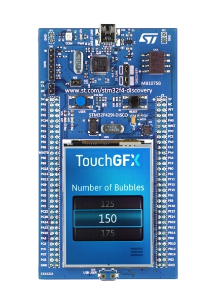
Because I was impressed by simplicity of cloud communication capable AT command set of WizFi360 platform I decided to try it with STM32 and real data from sensor instead of static one. Schematically I connected circuit in this way:
And in real world it looks like as follows:
After connecting this circuit, I started sending AT commands to the WizFi360 from STM32 over UART. I send and parsed replies from the commands which I mentioned in the previous section. It almost worked but only issue was with collision on TX line because it was now driven by two devices: My STM32 MCU and CP2104 USB-to-UART converter. For this reason, I checked board schematic and realized that there is possibility for switching UART (WizFi360 has two UART interface) connected to onboard CP2104 converter. So, I wanted to connect one to STM32 and second to CP2104.
Board rework
Because I had no switch with footprint used on board, I soldered pin headers and used jumpers instead. To summarize I desolder R4 and R5 which acted as a static configuration when no switch is mounted and soldered Samtec TSM-103-03-F-DV to SW3 position. Samtec TSM-103-03-F-DV is quite long pinhead and shorter would be better, but I had only TSM-103-03-F-DV in my toolbox from previous projects. I would like to thank Samtec because for previous project I received it as a free same.
After rework board looked as follows and after disconnecting jumpers UART TX was driven only by STM32. After connecting jumpers, it become connected to onboard CP2014 again and even more, after rework I can select if UART 0 or 1 is connected to CP2104 (which will be beneficial in next part when I will flash firmware to the device).
Custom WizFi360 Firmware
After I completed my first experiments with AT commands, I made one step further and started learning of WizFi360 internals. I had solution with processor (STM32) and Wi-Fi Module (WizFi360) but I want to make better single chip solution and utilize internal processor of WizFi360 for reading data from my sensors, thus removing need to use STM32.
Main information for me was in Other Resources section which contains description of W600-SDK:
https://docs.wiznet.io/Product/Wi-Fi-Module/WizFi360/Other-Resource/w600_sdk
At this page I found some information about chip which is covered under metal shield. It is W600 microcontroller from Winner Micro and documentation contains link to their website which contains more files and documents to download including W600 chip datasheet. At vendor webpage we can for example see following block diagram which highlights most features of the chip.
Development environment
Winner Micro offers eclipse-based IDE for developing for their W600 chips which are used on WizFi360 module. I tried it but I was unable to get compilation working on Windows. Instead, I chosen different approach. I unzipped Winner Micro SDK on Linux machine and connected remotely to this machine from Visual Studio Code. Sources I compiled in this virtual machine and then transferred files back to my main machine. At main machine I then flashed firmware to the device over UART using bootloader.
Very good is that W600 is based on Cortex-M3 core. For compiling, debugging and so on we can use common and reliable toolchain which is available in almost in every Linux distribution and we do not need to compile for some obscure instruction set like we had to in early ESP8266 days.
There are multiple ways how to flash compiled firmware to the device. I tried both SECBOOT and flashing over ROM. Most of time I used ROM bootloader. In case of my own firmware there were no differences but when flashing stock
(or updated) firmware provided by Wiznet, only way is using SECBOOT but it is still quite easy. I had issues with XMODEM transfers from Tera term, but ExtraPutty worked well.
My first program which I flashed to the device was simple hello world program which prints hello message on UART directly from CPU on WizFi360 module:
Porting My HTU21D library
After I setup compiling environment and get familiar with basic SDK structure, I started controlling first peripheral of W600 MCU. It was I2C controller. Controlling I2C on W600 MCU is easy. SDK has user-friendly driver for it. Also, there is demo showing I2C communication with EEPROM. After I get familiar, I ported my own library (available at Github) for this platform and later used this library for reading sensor values directly from Wi-Fi module and then sending it to the cloud. My testing project just read and printed temperature and humidity to the UART. This time connection was simpler because now I did not need to use STM32 for reading data from sensor. Instead, I connected sensor directly to PB13 and PB14 pins which I chosen in my firmware. Schematically connection looks as follows:
And in real world it looked as follows:
After writing, compiling, and flashing I got following output:
Connecting to network
Next step was to connect to Wi-Fi network from microcontroller. This was quite easy because there is demo for doing this.
Sending data to Azure
The next step was connecting to Azure IoT Hub using MQTT client. Luckily SDK has integrated MQTT client, I tried to use it according to demo but it did not work. I went to the code and see that library do not implement any kind of SSL/TLS negotiation which is mandatory for Azure IoT Hub. It does not allow unencrypted communication. Because there was no demo, I had to implement lot from scratch. After going over SDK I found some code working with TLS connections. Especially there is HTTPClientWrapper which initializes and handles lot of SSL/TLS stuff for making encrypted HTTP requests. I used it as a base for my wrapped MQTT client. It was not very simple because I had to change Makefiles and configs for enabling linking MQTT client and TLS libraries to the final binary.
But simple wrapping to the HTTPClientWrapper did not work. For a long time, I was out of ideas, but I decided to go lower (I like going lower) and begin low-level network debugging. I setup port mirroring on my router and forwarded all incoming and outgoing packets to and from my home network to my computer for analysis in wireshark. Note that troubleshooting TLS is extremely complicated because lot of information are encrypted, thus it is impossible to read them. But some information at the beginning of communication are not encrypted, so I used them for finding root cause(s) of my issue(s) as much as possible.
I very soon find packets related to MQTT connection on port 8883 and have seen that some handshakes are going on but after some time connection stuck, cloud start retransmitting last packet and later my router send him ICMP notification that device is not responsible anymore. I also checked that when connecting to Azure device stopped responding to pings.
My next step was trying changing SSL library. WM SDK contains two TLS libraries included: matrixSSL and PolarSSL. By default, project uses matrixSSL. Later I found way how to change this setting and then HTTPClientWrapper started opening encrypted connection using PolarSSL. Good part was that my microcontroller was not freezing anymore. Bad part was that cloud closed connection as soon as it was created. Using packet analysis I found that PolarSSL supports only outdated encryption methods and cloud did not allowed use them for commination, hence Azure closed connection with my device.
In this state I had two situations: with matrixSSL my firmware freeze and PolarSSL supports only outdated protocols. I thought that firmware freezing is done by some buffer overflow and consecutive hard fault. I tried several techniques to find it but without success. I also tried extending task stack size but also without success.
Debugging using openocd and GDB
Because W600 has standard Cortex-M3 core we can use standard debugging stuff compatible with ARM SWD (Serial Wire Debug). Chip vendor offers some documentation regarding this. Openocd is bundled with W600 SDK, but only for Linux and I need to connect to the device from windows. I downloaded vanialy openocd build for Windows. Bundled was older 0.10 version, so I also downloaded 0.10 version for ensuring compatibility with scripts even newer version is available. Scripts I used from W600 sdk. I used FTDI FT232 chip as a debugger. It is supported by OpenOCD but I had to write own config file for it.
After successful starting openocd, starting GDB and connecting to remote target I tried stepping over the code. I found that my firmware stuck in infinite loop consisting of checking one variable to zero. Function names indicates that it has something in common with cryptography. After additional hours of experimenting, I found that when disabling HW accelerated cryptography it start working and SSL communication continued. Without HW crypto it will be slower but do not stuck in infinite loop.
Fixing MQTT library
I achieved success with fixing previous issue by just disabling HW accelerated cryptography in configuration header file (It is write sad to me that over 6 hours of debugging resulted to single-line fix), but this was still insufficient for establishing connection with cloud. In wireshark I have seen that communication went some steps further and both server and client exchanged some data. At this point It was very hard to investigate what is going on because almost whole traffic was encrypted in this stage. For this reason, I had to print unencrypted data from my firmware. After next hours spend with debugging, I found that MQTT packets from library are not correctly formatted. This is quite sad. This library do not support SSL and even more it cant properly encode and parse packets. The issue in my case was in calculating packet size. Connect packet contains in case of Azure IoT Hub long strings and there is bug which resulted to wrong computation of Remaining length field. In fact algorithm was correct. It “properly” formatted variable number of bytes but there was other issue: variable for storing total length of packet had uint8_t data type, so packet sizes above 256 was not computed correctly because of data type overflow. This was also my case because Azure uses long passwords.
Fixing wrong SNI TLS header generation
Other issue which I found was one layer upper – at TLS level. HTTPClientWrapper which I used for using TLS sockets was improperly configuring SNI header containing server name. It formatted header using IP address of cloud server instead of hostname.
All these issues mentioned above, and some other minor issues took me over 120 hours of debugging, programming and experimenting until I get it working.
Outputs visualization
After I sent some data to the cloud, I created simple web application for visualizing them. It is created using ASP.NET Core. Cloud side I configured for sending data from IoT Hub to Service Bus Queue, then Logic App parse JSON and save new data to the Azure Storage Table. Application written in ASP.NET Core connects to Azure Storage Table and reads data.
Summary
At the end I have very nice solution with only single microcontroller shared for communicating with sensor and cloud. WizFi360 is very nice platform which allows you to develop in very simple and quick way using AT commands, but if you want you can go lower and write custom firmware which can results to much better solution in terms of power consumption, cost, performance and possibly reduced time to market. I think that the SDK for W600 chip which is under the WizFi360 module shield is not polished yet. Need for fixing it cost me most of time which I spend with device as part of this competition. Wiznet have some own SDK mentioned at website, but they do not publish them publicly. I guess they solved the same issues as I did because for example Azure IoT connectivity in their firmware with AT commands works well.
I want to spend more time with this device because I feel big potential of this device and module. I will most probably use WizFi360 in my future projects because I like it. In many aspects it is better than ESP8266. I like that it has standard ARM Cortex core, so I can utilize my skills from other microcontrollers. It lacks some features over ESP32 but most of them I never used.
At the end I would thank to Wiznet for sponsoring the contest and giving me opportunity to get, learn and play with their WizFi360 module and evaluation board for free. I enjoyed time spend with device and I hope that other contests also did.
Thanks for reading. Have a nice day.


