
STM32_OTA_Bootloader_W5500
An STM32F103 OTA bootloader that downloads firmware over W5500 Ethernet, stages it in W25Q64 flash, and installs it after CRC validation.
Thumbnail Image: AI-generated image
STM32 OTA Bootloader with W5500 — Ethernet-Based Firmware Update for STM32F103
PROJECT DESCRIPTION
📌 Overview
This project implements an Ethernet-based OTA firmware update bootloader for STM32F103C8T6 using the WIZnet W5500. A Python server running on a PC sends a new firmware image over TCP, and the STM32 application receives it through the W5500, stores it in external W25Q64 flash, then resets the board. After reset, the bootloader checks the OTA flag, reads the new firmware from external flash, validates it, and installs it into the internal application flash area.
This is not a Wi-Fi OTA example. It is a wired Ethernet OTA design, where the STM32 works as a TCP client and connects to a PC server through the W5500. The client sends a "GET firmware" request, then receives the firmware image in 512-byte chunks. This allows firmware updates without physically reconnecting a programmer or reflashing through ST-Link every time.
The project is clearly divided into three parts: the bootloader, the main application, and the PC server. The main application normally runs sensors and an LCD display, then starts the OTA download when a button is pressed. The bootloader runs after reset, checks whether an OTA update is pending, verifies the image, and jumps to the application. The README marks the project status as Complete / v1.0.
📌 Features
Ethernet-based OTA update
The STM32 connects to a PC server over TCP through W5500 and downloads the firmware image. The Python server listens on port 5678 and sends the OTA image in 512-byte chunks after receiving the STM32 client request.
Separated bootloader and application design
The internal flash is divided into a bootloader area and an application area. The bootloader runs on every startup, checks the OTA request flag, validates the existing application using a magic number and CRC, and jumps to the application if it is valid.
External flash staging
The downloaded firmware is not written directly into internal flash. It is first stored in W25Q64 external SPI flash. When the OTA flag is set, the bootloader reads the new image from W25Q64, verifies it, and then installs it into the internal application flash region.
CRC32 integrity check
Each OTA image includes a header containing firmware size, CRC32, version, and magic number. The bootloader uses that header to check whether the image is valid before installing or executing it.
Sensor application demo
Application v1 uses DHT11 and DS3231, while Application v2 adds MPU6050. The LCD displays sensor values and OTA progress, and the buttons are used for display mode switching and OTA triggering.
📌 System Architecture
AI-generated image
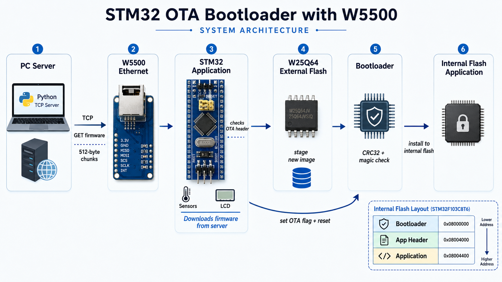
The overall update path is:
PC Server → W5500 Ethernet → STM32 Application → W25Q64 External Flash → Bootloader → Internal Flash Application
During normal operation, the STM32 application runs the sensor and LCD logic. When the OTA trigger button is pressed, the application initializes the W5500 TCP client, connects to the PC server, sends the "GET firmware" request, and receives the OTA image in chunks. The received data is stored in W25Q64 external flash, and the OTA header is checked as the data arrives.
After the download is complete, the application verifies that a valid image exists in W25Q64, sets the OTA flag, and resets the MCU. On the next boot, the bootloader reads this flag and, if an update is pending, reads the firmware image from external flash, writes it into the internal flash application region, validates CRC, commits the application header, and then jumps to the new firmware.
The internal flash layout is also clearly defined. The bootloader starts at 0x08000000, the application header is placed at 0x08004000, and the application firmware starts at 0x08004400. This separation allows the bootloader to remain protected while the application area is replaced during OTA.
📌 Role and Application of the WIZnet's Chip
AI-generated image
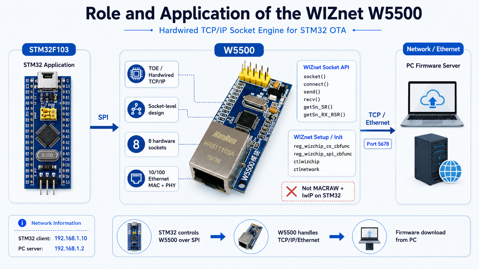
WIZnet chip used: W5500
In this project, the W5500 is the Ethernet controller that allows the STM32 to communicate with the PC firmware server over TCP. It is not used merely as a link interface. The project uses W5500 socket APIs to create a TCP client socket and connect to the firmware server.
This is best understood as a TOE / hardwired TCP/IP socket-level design, not a MACRAW + lwIP design. The code includes wizchip_conf.h and socket.h, and the W5500 initialization path uses WIZnet ioLibrary-style functions such as reg_wizchip_cs_cbfunc, reg_wizchip_spi_cbfunc, ctlwizchip, and ctlnetwork. The OTA client directly uses socket(), connect(), send(), recv(), getSn_SR(), and getSn_RX_RSR() to operate the W5500 TCP socket.
In other words, the STM32 is not running a software TCP/IP stack such as lwIP for this path. The STM32 controls the W5500 over SPI, while TCP connection handling and socket-level communication are performed through the W5500’s hardwired socket engine. This is the key reason the design is practical on a small STM32F103.
The W5500 initialization flow is also well defined. The code resets the W5500, registers chip-select and SPI callbacks, initializes the chip memory, checks the W5500 version register, checks PHY link status, and applies static network information. The STM32 client IP is set to 192.168.1.10, the PC server IP is 192.168.1.2, and the server listens on port 5678.
📌 Implementation Notes
The OTA image is not a raw firmware binary. It is structured as a 16-byte header plus the firmware binary. The header contains the magic number 0xABCDEFAB, image size, CRC32, and firmware version. The Python server reads application.bin, calculates a zlib CRC32, attaches the header, and outputs ota_image.bin.
On the STM32 application side, the OTA client checks that the W25Q64 flash area is erased before writing. After each write, it reads the data back and verifies that the flash write succeeded. The LCD shows OTA status messages and a percentage progress bar, which makes the update process visible to the user.
The bootloader reads the OTA header and firmware payload from W25Q64. It checks the magic number, confirms that the image size fits within the application area, writes the firmware to internal flash in chunks, and calculates CRC as it writes. If the final CRC matches the expected CRC from the header, the bootloader commits the application header and allows the new firmware to run.
If an OTA download or flash write fails, the application does not set the OTA flag and returns to normal operation. If the bootloader detects CRC, magic, size, or reset errors, it does not jump into an invalid application. This gives the design a basic level of update safety.
📌 Market & Application Value
AI-generated image
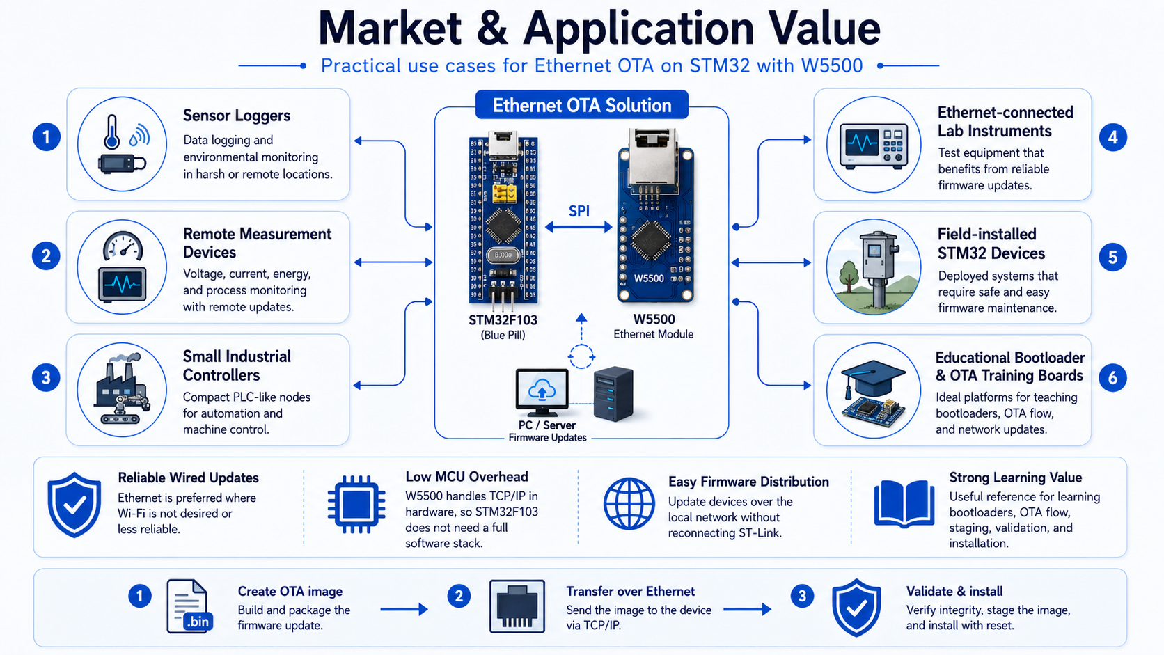
The most direct application is firmware update for STM32-based devices with wired network access. This is especially useful for embedded systems where Wi-Fi is not desired, not available, or less reliable than Ethernet.
Possible use cases include:
- sensor loggers
- remote measurement devices
- small industrial controllers
- Ethernet-connected lab instruments
- field-installed STM32 devices
- educational bootloader and OTA training boards
The W5500 is useful here because it allows TCP communication on a resource-constrained MCU without requiring the STM32F103 to run a full software TCP/IP stack. The W5500’s hardwired socket engine keeps the network side simpler for the MCU and makes the design easier to understand and reproduce.
This project also teaches the OTA process step by step: creating an image on the PC, transferring it over Ethernet, staging it in external flash, validating it in the bootloader, and installing it into internal flash. That makes it valuable as a reference for developers learning STM32 bootloaders and Ethernet firmware update flows.
📌 External Indicators
The README includes links to both a hardware demo and a PC server demo. The hardware demo shows the system running Application v1, starting the OTA process, installing the new image, and then booting Application v2. The PC server demo shows the server waiting for the STM32 client request and sending the firmware image in 512-byte chunks.
The documentation also includes a schematic diagram, pin configuration, memory layout, OTA image format, CRC explanation, and OTA flowchart. This makes the project easier to follow than a code-only example.
Related projects are also linked, including an STM32 custom bootloader with CRC, an ESP8266-based OTA bootloader, and a MicroSD cloud logger. This suggests that the author has been building a series of STM32 bootloader and sensor/logger projects around the same learning path.
📌 WIZnet Strategic Value
This project shows the W5500 being used as part of a firmware delivery and bootloader update pipeline, not just as a general TCP communication demo.
The most important point is that it uses the W5500 in a TOE / hardwired TCP/IP socket-level architecture. The STM32 uses WIZnet ioLibrary-style APIs to open a socket, connect to a server, receive firmware chunks, and send acknowledgements. That makes it a clean and practical reference for developers who want to implement Ethernet OTA on smaller MCUs.
In this context, the W5500 is not simply a network peripheral. It adds Ethernet update capability to the STM32 bootloader ecosystem. Compared with UART, USB, or SD-card updates, W5500-based OTA allows firmware to be distributed over a local wired network.
📌 Summary
STM32_OTA_Bootloader_W5500 is an STM32F103C8T6 project that implements OTA firmware update over W5500 Ethernet. The application downloads a firmware image from a PC TCP server, stores it in W25Q64 external flash, and then resets. The bootloader reads the staged image, verifies it, installs it into internal flash, and jumps to the new application.
The core technical value is its TOE / hardwired TCP/IP socket-level OTA design. The code uses wizchip_conf, socket.h, socket(), connect(), send(), and recv(), so this is not an lwIP-based MACRAW example. It is a direct W5500 socket-engine-based Ethernet OTA implementation.
📌 FAQ
Q1. What is this project?
It is an OTA bootloader project for STM32F103C8T6. The STM32 downloads firmware from a PC server through W5500 Ethernet, and the bootloader verifies and installs the new application.
Q2. What does the W5500 do?
It provides the Ethernet TCP connection between the STM32 and the PC firmware server.
Q3. Is this an lwIP / MACRAW implementation?
No. The code uses wizchip_conf.h, socket.h, socket(), connect(), send(), and recv(), which indicates a W5500 hardwired TCP/IP socket-level design.
Q4. Is the new firmware written directly to internal flash?
No. The application first stores the OTA image in W25Q64 external flash. After reset, the bootloader reads that image and installs it into the internal application flash region.
Q5. What is the OTA image format?
It consists of a 16-byte header plus the firmware binary. The header includes magic number, image size, CRC32, and version.
Q6. Why is CRC32 used?
The bootloader uses CRC32 to verify firmware integrity before allowing the new application to run. If the CRC check fails, the bootloader does not jump to the invalid firmware.
Q7. What development environment does it use?
The README describes the project as an STM32CubeIDE-based project using STM32F103C8T6, W5500, W25Q64, and a Python TCP server.