
M5StackとModbus RTUで産業用モーター(オリエンタルモーター)を動かす
M5Stack controls an Oriental Motor AZ driver via Modbus RTU over RS-485, using an RJ45/W5500 module for wiring convenience—plus the key 8E1 parity fix.
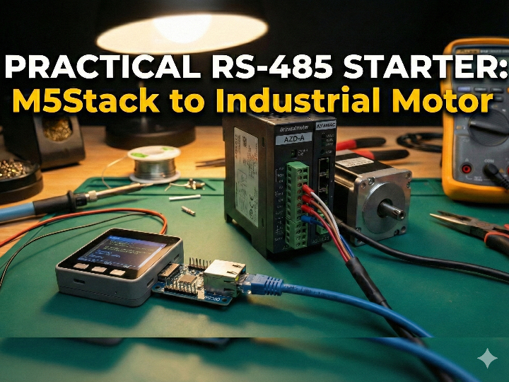
A practical RS-485(Modbus RTU) starter that uses an RJ45/W5500 LAN module for wiring & deployment convenience (Zenn: sheep_silica)
Introduction
This Japanese Zenn article shows a “make it move” path for controlling an industrial motor driver over Modbus RTU (RS-485) using M5Stack. It’s written for creators and engineers who have outgrown hobby stepper setups and now need industrial-grade behavior—things like moving heavier loads, holding absolute position, maintaining repeatability, and running reliably in long-term installations.
Source: https://zenn.dev/sheep_silica/articles/f6543757024637
Original language & author
- Language: Japanese (Zenn)
- Published: 2026-01-07
- Author: ひつじ (Zenn account:
sheep_silica)- In the Zenn profile, the author describes themselves as a creator/artist and lists a creative/engineering stack including TouchDesigner, Houdini, React, and Next.js.
- The author also maintains X (Twitter) accounts. (If you’re publishing this curation, adding an X screenshot makes it easy for readers to identify the author and their broader work.)
X accounts (for reference / screenshots):
- Main:
https://x.com/sheep_7s22n6M4i - Separate finance-related account is also noted by the author.

Source: https://x.com/sheep_7s22n6m4i

Source: https://www.silica-inc.jp/
What this project/article does
The article’s goal is very concrete: establish a reliable baseline for industrial motor control over Modbus by completing two “proof” actions:
- Build RS-485(Modbus RTU) communication from M5Stack to an Oriental Motor AZ driver
- Confirm control via Modbus registers by:
- Reading current position (encoder-based, 32-bit)
- Running motion using Direct Data Drive (writing a block of registers)
Hardware used in the article
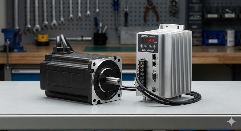
Motor driver: Oriental Motor AZ series
The example setup uses an AZD-AX driver with an AZM69M1C motor. The AZ series is highlighted for its encoder-based positioning behavior and practical “industrial” handling.
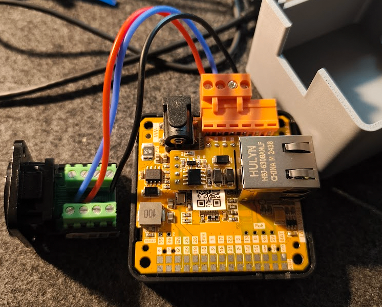
Controller: M5Stack + RJ45/W5500 LAN module
Instead of using an RS-485 unit, the author uses an RJ45-equipped W5500 LAN module. They note it’s convenient for deployments where you want PC-side control over a “network-looking” cable and prefer DIN-rail-friendly setups.
(Important: the control protocol here is still Modbus RTU over RS-485; the RJ45/W5500 module is used as a convenient physical/wiring form factor in this build.)
How it works (W5500’s role & the data flow)
Source: https://zenn.dev/sheep_silica/articles/f6543757024637
Source: https://zenn.dev/sheep_silica/articles/f6543757024637
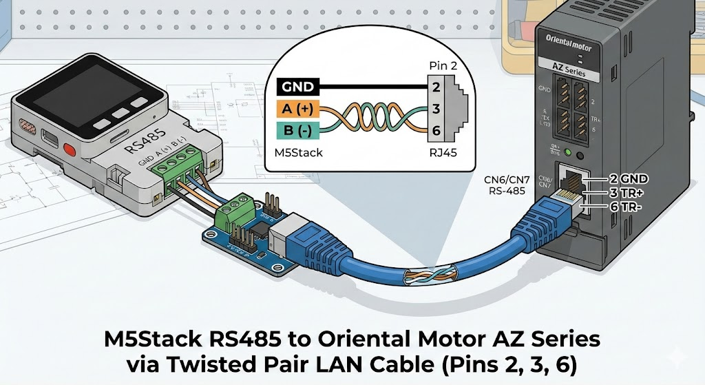
1) Physical layer: RS-485 wired over RJ45 (LAN cable as a convenient harness)
The AZ driver’s RS-485 port is RJ45, so using an RJ45 module on the controller side lets the author reuse common LAN cables as RS-485 wiring. Only three pins are used:
- RJ45 pin 2 = GND
- RJ45 pin 3 = TR+
- RJ45 pin 6 = TR-
These connect to the module’s GND / A / B terminals.
2) Protocol layer: Modbus RTU setup (the most common pitfall)
The article uses Arduino’s ModbusMaster library and assigns Modbus to Serial2 (RX=GPIO5, TX=GPIO15) on the M5Stack side.
The big gotcha is parity:
- Arduino defaults to 8N1 (no parity)
- The AZ driver defaults to 8E1 (even parity)
If you don’t match parity, nothing works—and this is exactly where many people get stuck.
Example configuration (core idea):
Serial2.begin(115200, SERIAL_8E1, 5, 15);
node.begin(1, Serial2); // slave ID = 1
3) Register I/O: reading and writing Modbus data
The author explains Modbus at the level you actually need for motion control: you read and write device registers using function codes, and vendor implementations sometimes require specific write modes (e.g., multi-register writes even for what looks like a single setting).
Two key demos (the “it works” proof)
1) Read current position (32-bit from two registers)
Position is returned as 32-bit, so the code reads two registers and combines them. The example register address is 0x00CC (two-register read).
2) Run motion with Direct Data Drive (write a block of 16 registers)
The article introduces Direct Data Drive as a convenient approach when your top-level controller is a microcontroller: you write a structured block containing target position, speed, accel/decel, current, etc. The example writes 16 registers starting at 0x0058.
What you can extend next
The post focuses on getting motion working, but notes that Modbus control can be extended to practical features such as:
- Sensor-based homing
- Software limits
- Alarm readout and reset
…by following the driver’s function and register documentation.
Why this matters (why this JP article is worth curating)
- It provides a reproducible “first success” route for industrial motor control via Modbus RTU—hardware wiring, serial config, and register transactions.
- It highlights the #1 real-world pitfall (parity 8E1) clearly, saving other users hours of trial-and-error.
- It frames hardware choices from a deployment perspective (RJ45 cabling, DIN-rail convenience), not only from a lab-bench perspective.
- The author’s background (creative coding + engineering) makes it a good reference for teams building physical installations, exhibits, and long-running systems—not just factory automation.
Quick reproduce checklist
- Hardware
- Oriental Motor AZ driver + motor (example: AZD-AX + AZM69M1C)
- M5Stack + RJ45/W5500 LAN module (author’s setup)
- Wiring
- RJ45 pins 2(GND), 3(TR+), 6(TR-) → module GND/A/B
- Serial / Modbus
ModbusMaster, Serial2 (RX=5, TX=15)- 115200, 8E1 (even parity) must match the driver
- Validation
- Read position: 0x00CC (two registers → 32-bit)
- Direct Data Drive: write 16 registers starting at 0x0058
Frequently Asked Questions (FAQ)
Q: Why is communication failing between M5Stack and the Oriental Motor AZ driver?
A: The most common cause is a parity mismatch. Oriental Motor AZ drivers default to Even Parity (8E1), while Arduino/M5Stack libraries typically default to No Parity (8N1). You must explicitly configure the serial connection to SERIAL_8E1 (e.g., Serial2.begin(115200, SERIAL_8E1, ...)), otherwise, the driver will ignore the commands.
Q: Why does this project use a W5500 LAN module for RS-485 Modbus RTU?
A: In this specific setup, the W5500 module is used primarily for its RJ45 connector form factor, not for Ethernet TCP/IP protocol. Since the Oriental Motor driver uses an RJ45 port for RS-485, using an RJ45-equipped module on the M5Stack allows for easy, clean wiring using standard LAN cables (using pins 2, 3, and 6 for GND, TR+, and TR-).
Q: What is "Direct Data Drive" in the context of this project?
A: Direct Data Drive is a control method where the master (M5Stack) writes a block of data (target position, speed, acceleration, etc.) directly to specific registers (e.g., starting at 0x0058) to trigger motion immediately. This is often simpler for microcontroller-based systems than managing complex stored data tables on the driver side.
Q: Can I use standard LAN cables for this RS-485 connection?
A: Yes, but you must ensure the pinout matches. The project utilizes a standard LAN cable where Pin 2 is GND, Pin 3 is TR+, and Pin 6 is TR-. This matches the pinout required to bridge the M5Stack module to the Oriental Motor driver’s CN1 port.
W5500 LAN 모듈을 이용한 RS-485(Modbus RTU) 실전 입문 (Zenn: sheep_silica)
Introduction
이 일본어(Zenn) 글은 M5Stack으로 산업용 모터 드라이버를 **Modbus RTU(RS-485)**로 제어해 “일단 움직이게 하는” 과정을, 실제 장비 구성과 코드로 보여주는 실전 가이드입니다. 글의 타깃은 하비용 스텝모터로는 부족해져 산업용 모터로 넘어가려는 제작자/엔지니어이고, “더 크고 무거운 것을 움직이기”, “절대 위치/각도 확보”, “상설 전시 등 장기 운용” 같은 요구가 있는 경우 산업용 모터가 유리하다고 설명합니다.
Original language & Author
원문 언어: 일본어(Japanese), Zenn
게시일: 2026-01-07
저자: ひつじ (Zenn 계정: sheep_silica)
프로필에서 본인을 작가/크리에이터로 소개하고, 사용 기술 스택으로 TouchDesigner / Houdini / React / Next.js를 언급합니다.
저자는 Zenn 외에도 X(트위터) 계정을 운영합니다. (기사 업로드 시 X 스크린샷을 함께 첨부하면, 저자 정체성과 활동 분야를 독자가 빠르게 파악하는 데 도움이 됩니다.)
참고(X 계정):
메인:
sheep_7s22n6M4i(금융/돈 관련 분리 계정도 별도로 표기됨)
What this project is
이 글의 목표는 “산업용 모터를 Modbus로 제어하는 최소 성공 경로”를 제공하는 것입니다.
오리엔탈모터 AZ 시리즈 드라이버/모터를 준비하고
M5Stack에서 Modbus RTU(RS-485) 통신을 구성한 뒤
레지스터 읽기/쓰기를 통해
현재 위치 읽기(엔코더 기반 32bit)
**Direct Data Drive(다이렉트 데이터 운전)**로 실제 구동
까지 “동작 확인”을 끝냅니다.
Hardware setup (저자 실사용 구성)
1) 모터 드라이버: 오리엔탈모터 AZ 시리즈
예시 구성은 AZD-AX 드라이버 + AZM69M1C 모터이며, 엔코더 기반이라 전원 OFF 후에도 위치가 유지되는 점을 장점으로 듭니다.
2) 컨트롤러: M5Stack + W5500 LAN 모듈
저자는 M5Stack RS-485 유닛 대신 LAN 포트가 달린 W5500 모듈을 사용합니다. 이유로는
PC에서 네트워크로 지시를 내릴 수 있고
DIN 레일 설치가 가능해 운영이 편하다는 점
을 언급합니다.
How it works (W5500 역할 & 데이터 흐름)
이 글의 핵심 구조는 “제어는 RS-485(Modbus RTU), 운영/배선 편의는 RJ45/W5500 모듈”로 이해하면 됩니다.
1) 물리 계층: RS-485를 RJ45(랜 케이블)로 배선
AZ 드라이버 쪽 RS-485 포트가 RJ45 형태라서, M5Stack 측도 RJ45로 맞추면 일반 LAN 케이블을 RS-485 배선에 활용할 수 있습니다(트위스트 페어라 취급이 편함).
저자가 제시한 배선은 핀 3개만 사용합니다.
RJ45 2번 = GND, 3번 = TR+, 6번 = TR-
이를 W5500 모듈의 GND / A / B에 연결
2) 프로토콜 계층: Modbus RTU 설정(가장 흔한 함정 포함)
M5Stack Arduino 환경에서 ModbusMaster 라이브러리를 사용하며, W5500 모듈에서는 **Serial2(RX=GPIO5, TX=GPIO15)**를 사용한다고 설명합니다.
그리고 이 글에서 가장 중요한 “실패 포인트”를 짚습니다.
Arduino 기본은 8N1(패리티 없음)
AZ 드라이버 기본은 8E1(짝수 패리티)
→ 이 설정이 맞지 않으면 통신이 안 되고 여기서 막히는 사람이 많다고 강조합니다.
예시(핵심만):
Serial2.begin(115200, SERIAL_8E1, 5, 15);
node.begin(1, Serial2);
3) 데이터 계층: 레지스터 읽기/쓰기
Modbus는 “레지스터”를 읽고/쓰는 구조이며, 기능은 펑션 코드로 구분된다고 설명합니다. 또 제조사에 따라 “단일 레지스터도 0x10(복수 레지스터 쓰기)을 요구” 같은 관례가 있어 펑션 코드 개념을 이해하면 도움이 된다고 덧붙입니다.
Two key demos (재현 핵심 2개)
1) 현재 위치 읽기(32-bit)
위치 정보는 **32-bit(4바이트)**로 반환되므로, 2개 레지스터를 읽어 32-bit로 합친다고 설명합니다. 예시 주소는 0x00CC(2레지스터)입니다.
2) Direct Data Drive로 구동(16레지스터 Write)
저자는 마이컴에서 운전시키기 편한 방식으로 Direct Data Drive를 소개합니다. 목표 위치/속도/가감속/전류 등을 묶어 쓰는 방식이며, 예시에서는 0x0058부터 16레지스터를 한 번에 쓰는 형태로 제시됩니다.
What else you can do (확장 포인트)
이 글은 “일단 움직이게 하기”에 초점을 두지만, Modbus로 가능한 기능이 더 많다고 명시합니다. 예를 들면
센서 연동 원점 복귀
소프트웨어 리미트
알람 정보 읽기/리셋
등이며, 자세한 레지스터는 기능편 매뉴얼을 참고하라고 안내합니다.
Why it matters (왜 큐레이션할 가치가 있나)
산업용 모터 제어의 ‘최소 성공 경로’를 실제 배선/설정/코드로 제시합니다.
초보자가 가장 자주 막히는 패리티(8E1) 같은 통신 설정 포인트를 명확히 찝어줍니다.
W5500 모듈을 선택한 이유(네트워크 지시, DIN 레일 설치)까지 제시해, “작업실/전시/현장 운용” 관점에서 설득력이 있습니다.
저자가 크리에이티브 코딩/미디어아트 툴(TouchDesigner 등)도 다루는 사람이라, 산업 장비를 창작/설치 환경에 연결하는 관점이 글 전체에 녹아 있습니다.
Quick reproduce checklist
하드웨어
오리엔탈모터 AZ 드라이버 + AZ 모터(예: AZD-AX + AZM69M1C)
M5Stack + W5500 LAN 모듈(저자 구성)
배선
RJ45 2(GND), 3(TR+), 6(TR-) → 모듈 GND/A/B
통신
ModbusMaster, Serial2(RX=5, TX=15)
115200, 8E1(짝수 패리티) 반드시 확인
기능 확인
위치 읽기: 0x00CC (2레지스터 → 32bit 결합)
Direct Data Drive: 0x0058부터 16레지스터 Write
원하시면 이 “완성본(한국어)”을 같은 구조로 영문 버전도 바로 만들어드릴게요. (특히 WIZnet Maker Site용으로 제목/톤/태그까지 맞춰서)