How to Mount Projects With Feather-shaped Microcontroller Boards in a Control Cabinet.
I would like to present a small housing set that closes exactly this gap.

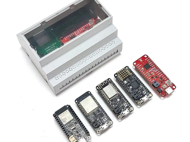
Microcontroller boards in Feather design e.g. from Adafruit, Sparkfun and other manufacturers are available for various microcontroller types and are therefore very well suited for prototyping, hobby projects or even small series.
But until now there was no ready solution to mount such projects in a cabinet on DIN rails. I would like to present a small housing set that closes exactly this gap.
Supplies
Materials:
- ArduiBox Feather kit
- Feather or ThingPlus microcontroller board
- Feather Wing board (option)
Tools:
- Soldering Iron
- Solder Wire
- Screwdriver
Step 1: Introduction ArduiBox Feather
ArduiBox Feather is a DIN rail enclosure set with matching PCB for Feather microcontroller boards and the corresponding shields (also called wings for Feather boards).
The ArduiBox contains a 6 module DIN rail case and a PCB with an integrated 5V switching regulator, so that the Feather boards can be powered from the industry standard 24V DC voltage. Beside the slot for the microcontroller board there is another slot for a Feather wing, a W5500 Ethernet module and breadboard area for own circuits.
- Terminals power supply
- Terminals for proto board
- Slot for Feather board
- Slot for Feather wing
- Slot for Ethernet module
- voltage regulator (9..30V Vin / 5V Vout)
- Breadboard / proto board area
- GPIO pins for proto board
- Power pins (Vin, GND) for proto board
- Reset button
Step 2: Assembly
The case set comes as a diy kit. The PCB is already pre-assembled with the SMD components for the voltage regulator, so that only a THT components must be soldered by hand.
The PCB is then mounted in the bottom shell of the housing using 2 screws.
Step 3: Commissioning
Now the Feather board and if necessary also the Wing and the Ethernet module can be attached.
Next to the breadboard area there is a 6pin terminal which can be used freely. If you want to use a Feather wing that communicates with the outside world - for example a CAN bus wing - you can connect the terminal of the wing (which will be inside the case later) with short wires to the solder pads next to the terminal. When the housing is closed, these signals are then available via the terminal on the board.
The terminals are protected by covers in the upper shell of the housing, which can be broken out if necessary.
Step 4: Power Supply
The ArduiBox Kit can be powered in two ways. Either a DC voltage between 9V and 30V DC is connected to the 2-pole power supply terminal or the circuit is supplied via the USB connection of the Feather board. There is an extra opening in the side of the case to connect a USB cable even when the top shell is mounted.
Step 5: Ethernet
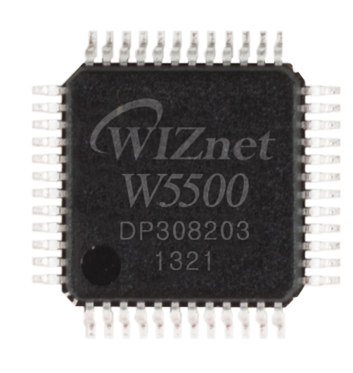
Ethernet is often required for applications in control cabinets, as wireless communication often does not work due to the metal housing of the control cabinets. There are also corresponding Ethernet feather wings, but for mechanical reasons these wings do not fit into the top-hat rail housing. Therefore, a plug-in socket is provided on the circuit board for a commercially available Ethernet module with a Wiznet W5500 Ethernet controller.
This module is compatible with the W5500 Ethernet wing from Adafruit and is connected identically to the microcontroller board, so that you can adopt the source code from Adafruit without making any changes.


