
ESP32 Industrial Signal Tower Controller
ESP32-C3 signal tower controller for infrastructure alerts: ESPHome-based logic, heartbeat supervision, and validated W5500 Ethernet for wired status indication
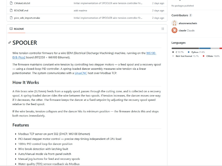
ESP32 Industrial Signal Tower Controller: a networked status light controller with validated W5500 Ethernet
Introduction
This project builds an industrial signal tower controller on ESP32-C3 and adds a validated W5500 Ethernet path for infrastructure-oriented deployments.
For readers outside industrial automation, an industrial signal tower—also called a stack light or tower light—is the column-shaped red/yellow/green status lamp often mounted on machines, cabinets, or production equipment. Its job is simple: make system state visible from across the room. In factories and equipment rooms, that kind of visual signaling is used to show conditions such as normal operation, warnings, or alarms so that operators and technicians can react quickly. Commercial automation vendors describe stack lights in exactly this role: clear, immediate machine or process status indication in factories, warehouses, and industrial environments. (Ifm)
In the uploaded ZIP snapshot, this repository is not a generic RGB lamp project. It is documented specifically as a controller for infrastructure monitoring visualization: datacenter racks, wiring cabinets, production equipment, energy systems, and control-room style deployments. The project combines hardware notes, power and network design documents, ESPHome firmware examples, and prototype validation records into a coherent build package. Uploaded ZIP snapshot
What this project is
AI-generated image
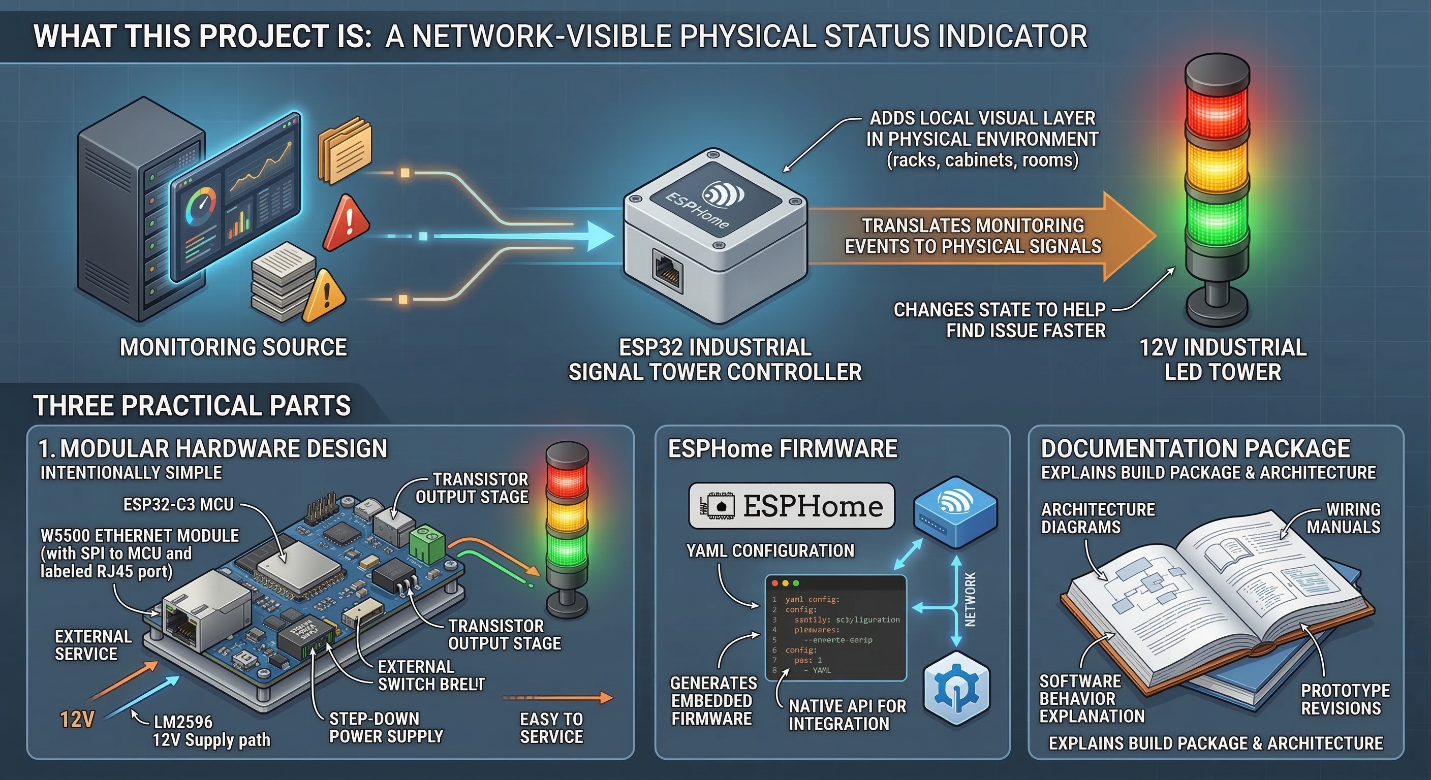
At its core, this project turns a simple 12 V industrial LED tower into a network-visible physical status indicator.
The uploaded documentation describes the controller as a bridge between a monitoring source and a physical signal device. Instead of forcing technicians to rely only on dashboards, logs, or chat alerts, the system adds a local visual layer in the physical environment. That idea is easy to understand: if a rack, cabinet, or room has a problem, the signal tower at that location changes state so someone can find the issue faster.
The current repository snapshot shows three practical parts:
- a modular hardware design built around an ESP32-C3, W5500 Ethernet module, step-down power supply, and transistor output stage,
- ESPHome firmware for both validation and operational use,
- and documentation that explains architecture, wiring, software behavior, and prototype revisions.
That makes the project feel closer to a small deployable infrastructure device than to a one-file microcontroller demo.
What ESPHome is doing here

Image source: https://esphome.io/
AI-generated image
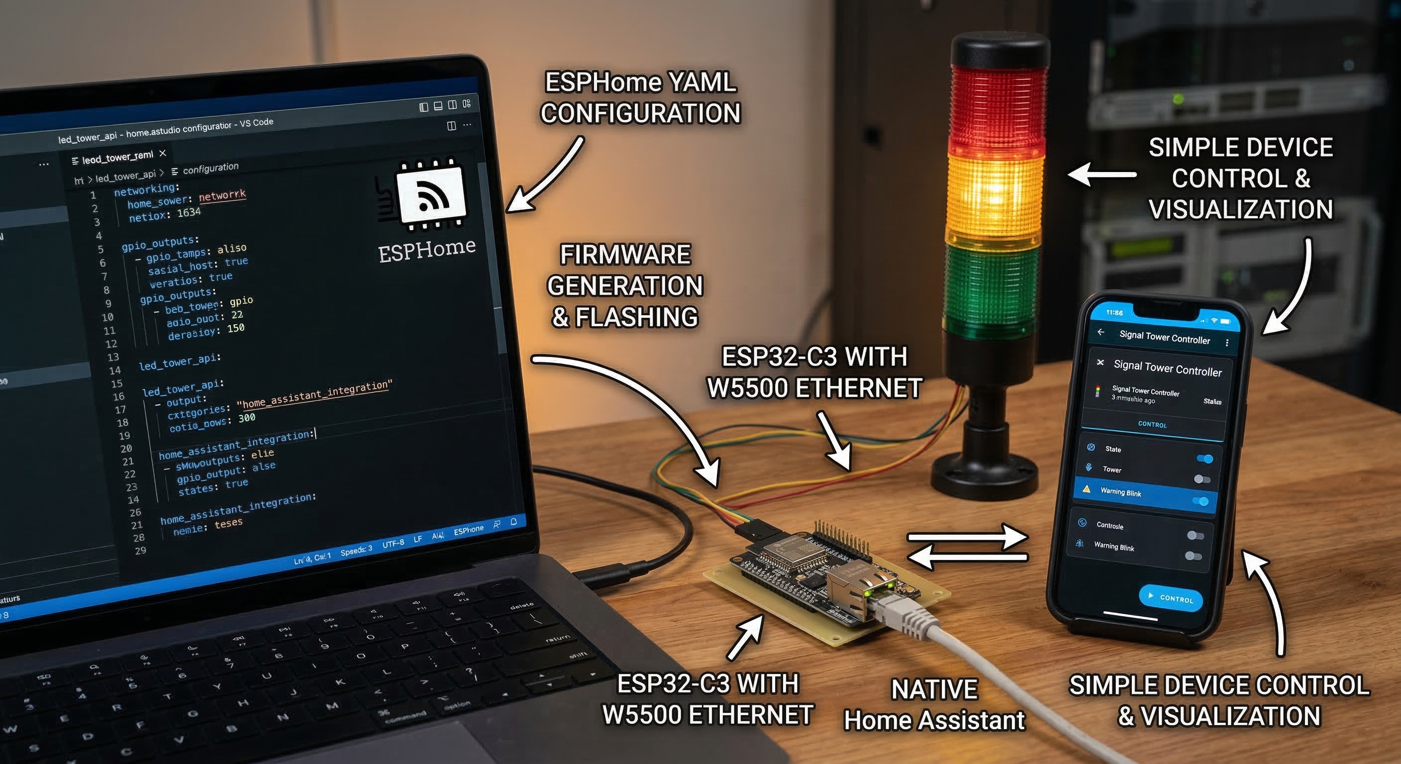
The firmware side is built with ESPHome.
For non-specialists, ESPHome is a configuration-driven firmware framework commonly used with Home Assistant. Instead of writing a full custom application in C or C++, the developer describes the device in YAML—networking, GPIO outputs, control entities, and behavior—and ESPHome generates the embedded firmware. Its native API is designed to let Home Assistant communicate directly with the device over the network. (ESPHome - Smart Home Made Simple)
That choice matters in this repository because it explains the software philosophy. The signal tower itself stays simple, while the more complex logic—automation rules, dashboards, and heartbeat generation—can live in the higher-level platform around it.
Author and project context
The available materials point to an individual or small-team infrastructure-oriented build, not to a large public hardware vendor or an already productized commercial line.
What stands out in the repository is the type of problem being solved. The documentation is consistently framed around real operational environments: server racks, wiring centers, industrial automation environments, energy infrastructure, and control rooms. That focus gives the project more external value than a decorative light or maker-only demo, because it is clearly trying to solve an operations problem: faster fault localization through physical signaling.
The hardware strategy also reflects that mindset. The design deliberately avoids jumping straight to a custom integrated PCB. Instead, it uses replaceable modules, perfboard prototypes, a low-side transistor switching stage, and a simple external 12 V supply path. That is the kind of design choice usually made when serviceability, rapid iteration, and low-risk prototyping matter more than aesthetic miniaturization.
How it works
AI-generated image
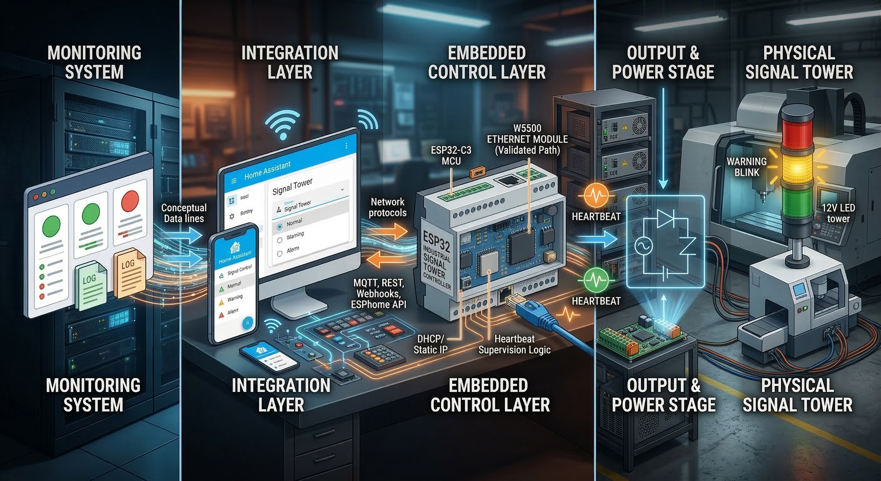
The easiest way to understand the system is as a four-stage chain:
Monitoring system → integration layer → ESP32 controller → output stage → physical signal tower
That structure is explicitly documented in the repository, and it keeps the project readable.
1) Monitoring system
The upstream source can be anything that knows the health of the environment: server monitoring, industrial monitoring, control scripts, or automation rules.
The uploaded architecture documents name examples such as Checkmk, Zabbix, Prometheus, and custom scripts. In other words, the signal tower is not tied to one brand of monitoring stack. It is meant to sit downstream of whichever system already knows that something is wrong.
2) Integration layer
The integration layer is where monitoring events are translated into commands the controller can understand.
The docs describe several possible paths—MQTT, REST, webhooks, or automation scripts—but the visible production-oriented firmware example uses Home Assistant + ESPHome API as the active control path. In that YAML, the tower state is exposed as a selectable entity, heartbeat supervision is exposed as a switch, and heartbeat pings are exposed as a button-like trigger. That means the controller is designed to receive a small set of status commands from an external orchestration layer rather than compute infrastructure health by itself. ESPHome’s native API is designed exactly for this kind of direct client/device integration. (ESPHome - Smart Home Made Simple)
3) Embedded control layer
The ESP32-C3 is the local decision point.
In the uploaded led_tower.yaml, the firmware maintains a compact state model: Off, Normal, Warning, Warning Blink, Alarm, Alarm Blink Slow, and Alarm Blink Fast. Only one state is active at a time. The code also implements a heartbeat supervision mechanism. If the controller stops receiving heartbeat pings for the configured timeout, it overrides the normal status display and switches to a communication-loss pattern. That is a good operational detail because it prevents the tower from continuing to show stale status after the control path has died.
For readers unfamiliar with the term, a heartbeat in this context is just a periodic “still alive” signal. If those pulses stop, the device assumes communication is no longer trustworthy.
4) Output and power stage
The hardware side is intentionally simple and easy to service.
The uploaded schematic documentation shows a common +12 V tower with each LED segment switched on the low side by a small NPN transistor. In plain language, the ESP32 does not power the lamp directly. Instead, each GPIO drives a transistor that turns the red, yellow, or green lamp channel on and off. The measured LED load in the hardware docs is very small—well below what would require relays or heavy power electronics—so the design stays lightweight and low-cost.
The power architecture is also straightforward: the tower runs from 12 V, and an LM2596 step-down converter supplies the ESP32 controller. The prototype documentation notes that the current physical build uses an external 12 V supply, while the broader design also allows PoE-splitter-based deployments.
Where WIZnet fits
AI-generated image
WIZnet appears here as the wired Ethernet path, not as the core logic of the device.
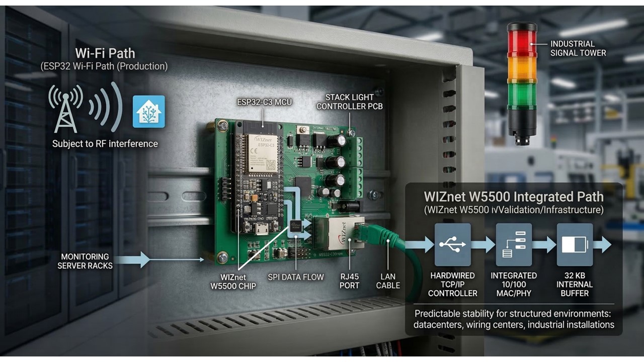
The uploaded firmware examples show two networking directions:
- a production-style Wi-Fi ESPHome configuration for integration with Home Assistant,
- and a separate W5500 Ethernet validation configuration used to prove wired connectivity on the Rev.B hardware.
That distinction matters. The current repository shows a design that is network-flexible, but not a single final firmware image running Wi-Fi and Ethernet simultaneously in one polished deployment profile. The safer reading is: Wi-Fi is used in the main operational example, while W5500 Ethernet has been successfully validated and is documented as the preferred medium for infrastructure-oriented installations.
That preference is also consistent with the project’s own reliability notes. The documentation explicitly argues that wired Ethernet is preferable to Wi-Fi in structured environments such as datacenters, wiring centers, and industrial installations because it is more predictable and less exposed to RF-related issues.
Technically, the Ethernet test firmware uses W5500 over SPI. WIZnet’s official documentation describes W5500 as a hardwired TCP/IP Ethernet controller with integrated 10/100 MAC/PHY, 8 sockets, and 32 KB internal buffer memory, connected to the host MCU via SPI. That is a natural fit for this kind of controller, where the MCU only needs a dependable wired interface rather than a full custom Ethernet stack from scratch. (WIZnet 문서 시스템)
Why it matters
This project matters because it turns a very familiar industrial component into a network-aware operations tool.
A conventional stack light already helps people see machine state from a distance. What this repository adds is a cleaner path from monitoring software to physical visual signaling. That is valuable in places where the problem is not “detecting a fault” but finding the right rack, cabinet, or equipment quickly once a fault has already been detected. Commercial vendors describe stack lights in exactly that broader role: fast visual communication of machine or process status in factories and technical facilities. (WERMA)
The uploaded ZIP snapshot is also stronger than a typical hobby proof-of-concept. It includes hardware notes, prototype revisions, ESPHome firmware examples, reliability considerations, and a documented heartbeat/fallback model. That gives the project practical external value even before it becomes a finished product: it shows a reproducible way to build a small infrastructure alert endpoint rather than just a blinking light.
Market and industry context
AI-generated image
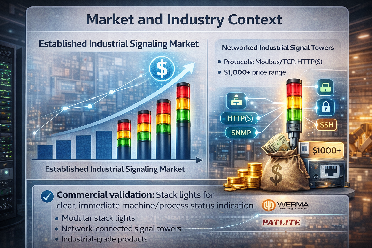
A clean public market-size figure for small networked signal-tower controllers specifically is hard to verify from high-quality public sources. The safer and more useful market reading is through the existing commercial stack-light and smart signaling market.
That market is clearly real. WERMA sells a broad range of industrial signal towers and stack lights as modular products for status signaling across different environments. PATLITE goes even further with network-connected products: its catalog includes stack lights with Modbus/TCP and HTTP(S) control, as well as network-monitoring signal towers that support protocols such as SNMP, HTTP/S, SSH, Socket, DHCP, and can trigger alerts based on network conditions. (WERMA)
That is the strongest commercial validation for this repository’s direction. It shows that “a networked status tower for infrastructure or machine monitoring” is not a made-up category. Commercial products already exist, and some are sold at distinctly industrial price points. For example, PATLITE’s store lists a Modbus/TCP + HTTP(S) tower in the mid-hundreds of dollars and higher-end Ethernet network-monitoring towers above US$1,000. (PATLITE 쇼핑몰)
In other words, this repository does not need to invent a market. It fits into an existing one, but from a more open and modular angle.
External value and author context
The strongest external-value signal here is not a large public company profile behind the repository. It is the problem framing and the engineering packaging visible in the materials.
The repository is consistently aimed at real operational environments: server racks, wiring centers, industrial automation areas, and control-room style visibility. That gives it more practical value than a decorative indicator project. The accessible public footprint around the author appears limited, so the safest interpretation is that this is an individual or small-team infrastructure-oriented build rather than part of a published commercial hardware line.
That is not a weakness by itself. In fact, the project’s value comes from showing a credible low-cost path into a category that is usually served by vendor products. Commercial examples such as WERMA’s configurable signal towers, PATLITE’s network-monitoring towers, and Caron Engineering’s CNC-oriented smart status light system all show that the surrounding market already values machine- and infrastructure-visible status indication as a real operational product type. (WERMA)
Hybrid-network interpretation
This project is best described as hybrid in architecture, but wired-first in intent.
The uploaded ZIP snapshot shows two network directions:
- a Wi-Fi ESPHome production-style configuration for Home Assistant integration,
- and a W5500 Ethernet validation path on the Rev.B hardware.
So the repository is not Ethernet-only. At the same time, its own reliability documentation explicitly says that wired Ethernet is the preferred medium for production-oriented infrastructure deployments, while Wi-Fi is treated as more suitable for development, temporary setups, or places without structured cabling. That makes the current project best understood as a dual-path design that is still converging toward a wired-first deployment model. The ESPHome stack itself supports this kind of device/platform split well because its native API is built for direct low-latency integration with Home Assistant, while its web server and REST/event APIs support external tooling when needed. (ESPHome - Smart Home Made Simple)
So, if this needs a short classification:
- Architecturally hybrid: yes
- Operationally preferred path: wired Ethernet
Productization potential
AI-generated image
The repository does not show that this controller is already sold as a finished commercial product.
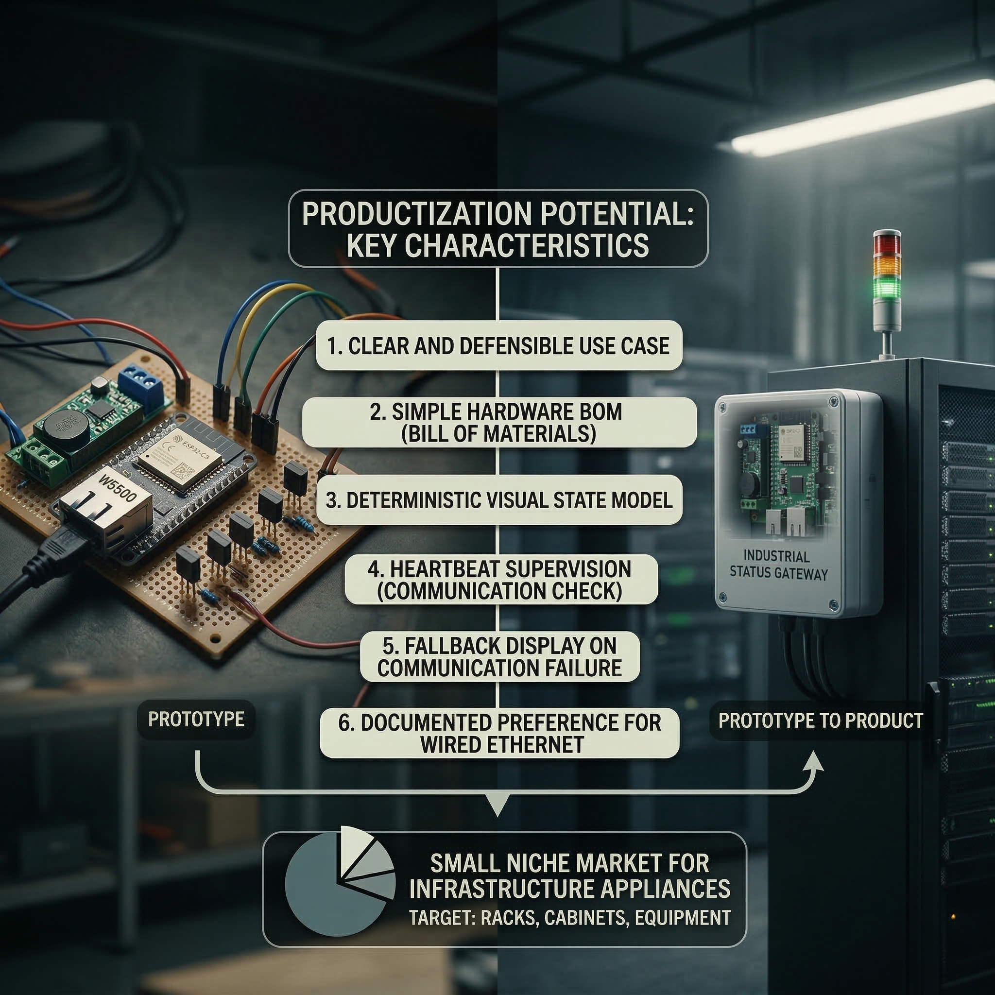
What the available materials do show clearly is that it has several product-like characteristics:
- a narrow and defensible use case,
- a simple hardware bill of materials,
- a deterministic visual state model,
- heartbeat supervision,
- a fallback communication-loss indication,
- and a documented preference for wired deployment in structured environments.
Those are all signs of a design that could plausibly evolve into a small infrastructure appliance, especially for racks, cabinets, or machine zones where a full-blown commercial network tower would be excessive or too expensive.
The strongest commercialization angle is therefore not “mass-market smart lighting.” It is small-scale industrial or infrastructure visibility tooling—a niche, but a real one.
Why W5500 was used
A concise way to explain the W5500 choice in this project is that it fits the ESP32-C3 + ESPHome design unusually well. The key hardware point is that the ESP32-C3 does not include an integrated Ethernet MAC, so adding wired Ethernet is more naturally done through an external interface, especially a SPI Ethernet device, rather than through the more typical RMII PHY path used on other ESP32 variants. In that context, W5500 is a practical choice because ESPHome supports it directly as an official SPI Ethernet chipset, which keeps software integration simple. At the hardware level, W5500 also works well for this kind of modular design because it is a one-chip Ethernet controller with SPI connectivity, integrated 10/100 Ethernet MAC/PHY, socket support, and internal buffering. That makes it a good fit for a project that wants to add reliable wired Ethernet to a compact ESP32-C3 device without increasing hardware and firmware complexity more than necessary.
Quick notes
A few caveats are important.
First, the repository currently reads as a well-documented prototype path, not as a finished hardware product line. The production firmware example is Wi-Fi based, while Ethernet is shown as validated and documented on Rev.B rather than fully replacing the main operational example in the same YAML profile.
Second, the project is clearly intended for monitoring visualization, not for functional safety. Its own documentation makes that boundary explicit. That is the right position: a stack light like this can improve operational awareness, but it is not a substitute for certified safety control.
Third, the value here is as much about integration design as about hardware. The combination of ESPHome, Home Assistant, heartbeat supervision, and a wired network option makes the project easier to extend than a fixed-function light controller.
Q. What is the ESP32 Industrial Signal Tower Controller?
A. It is a networked device that turns a standard industrial signal tower (stack light) into a smart visual indicator. It uses an ESP32-C3 to display physical alerts (red/yellow/green) for server racks, datacenters, or production equipment.
Q. How does it know when to trigger an alert?
A. It connects to network monitoring systems (like Home Assistant, Checkmk, or Zabbix) using ESPHome firmware. When the upstream system detects an issue, it sends a command over the network to instantly change the tower's light state.
Q. Why use the WIZnet W5500 Ethernet chip in this project?
A. The WIZnet W5500 provides a highly stable, wired local network connection. While the ESP32 supports Wi-Fi, a hardwired Ethernet connection is strictly preferred in industrial and datacenter environments to avoid wireless interference and ensure critical alerts are never missed.
Q. What happens if the network connection drops?
A. The firmware includes a "heartbeat" supervision feature. If the controller stops receiving regular communication pings from the main server, it automatically flashes a specific "communication-loss" pattern so operators know the data is stale.
Q. Who is this project designed for?
A. IT operations teams, datacenter managers, and industrial engineers who need a fast, reliable physical indicator to locate equipment faults across a room, rather than relying solely on screen dashboards.
References
https://esphome.io/components/api/
https://esphome.io/web-api
https://www.home-assistant.io/integrations/esphome/
https://www.werma.com/en/Product/Signal-towers/
https://shop.patlite.com/
https://shop.patlite.com/2-tier-Network-Monitoring-Signal-Tower-p/nhb6-2-ry.htm
https://shop.patlite.com/Network-Monitoring-Signal-Tower-p/nhv4-3m-ryg.htm
https://shop.patlite.com/Network-Monitoring-Signal-Tower-p/nhv6-3d-ryg.htm
https://www.caroneng.com/products/smart-light/
https://docs.wiznet.io/Product/Chip/Ethernet/W5500