



Bi-directional wireless power flow for medium duty vehicle grid connectivity
This DOE 20kW bidirectional wireless-charging truck used WIZnet Ethernet and industrial WiFi bridges to carry vehicle BMS status between two power-control DSPs
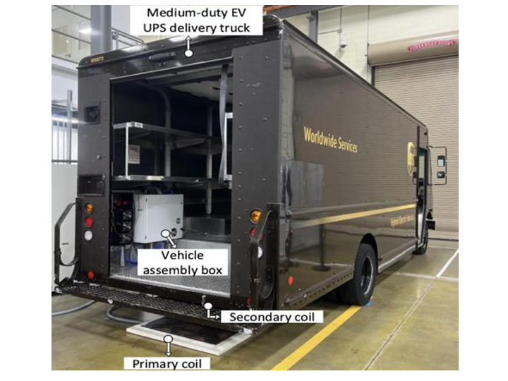
20 kW Bidirectional Wireless Charging for a Medium-Duty Truck: A WIZnet-Connected Ground-to-Vehicle DSP Network
Summary
A U.S. DOE–funded consortium led by CALSTART and ORNL integrated 20 kW bidirectional wireless charging into a medium-duty delivery truck. SPI-connected WIZnet Ethernet modules linked the ground- and vehicle-side DSPs to industrial Wi-Fi bridges, carrying vehicle battery status across the charging air gap.
Overview
The project developed a high-power bidirectional wireless power-transfer system for Class 5 and Class 6 medium-duty plug-in hybrid delivery trucks.
Its objectives included:
Charging a vehicle without a conductive cable
Returning energy from the vehicle battery to the grid
Supporting the approximately 11-inch ground clearance of a delivery truck
Connecting stationary energy storage to the ground-side DC link
Enabling several power-flow paths among the grid, stationary battery, and vehicle
Preparing for future fleet and microgrid energy management
Exchanging operating status between the ground- and vehicle-side power controllers
Vehicle-side hardware was integrated into a Workhorse plug-in hybrid step van and tested at ORNL. During the first two budget periods, the team completed converter development, Double-D coils, the LCC-LCC resonant network, DSP control, hardware-in-the-loop testing, and vehicle integration.
The research platform combined:
A 480 V three-phase grid connection
A bidirectional grid-interface converter
A stationary energy-storage system
A ground-side high-frequency inverter/rectifier
Double-D wireless-power couplers
A double-sided LCC-LCC resonant network
A vehicle-side rectifier/inverter
A 60 kWh vehicle battery
Ground- and vehicle-side DSP controllers
CAN communication with the vehicle BMS
WIZnet Ethernet interfaces
Industrial Wi-Fi bridges across the vehicle-to-ground gap
The project was therefore more than a wireless battery charger. It was a distributed energy system capable of coordinating the grid, stationary storage, and a vehicle battery.
How the Research Consortium Operated
U.S. Department of Energy and NETL
DOE established the technical objectives, budget periods, and project milestones. The related peer-reviewed publication states that the project was funded by the DOE Vehicle Technologies Office and managed through NETL. (Oak Ridge National Laboratory)
| Budget period | Primary purpose |
|---|---|
| BP1 | WPT converter, coil, resonant-network, and control development |
| BP2 | Vehicle integration, HIL, battery and fleet analysis, and laboratory validation |
| BP3 | UPS site deployment and real-world fleet demonstration |
BP1 and BP2 were completed. The planned BP3 field demonstration was not completed.
CALSTART
CALSTART was the formal recipient organization and the project’s programmatic coordinator.
CALSTART is a U.S. nonprofit organization that supports clean-transportation technology development, demonstration, assessment, validation, market acceleration, and policy programs. It connects government agencies, research organizations, fleets, manufacturers, and technology companies. (CALSTART)
Its role in this project can be understood as coordinating:
The federal award and consortium
Research and industry participants
The delivery-fleet use case
Demonstration planning
Fleet-level benefit and business-case analysis
The transition from laboratory research toward market deployment
Oak Ridge National Laboratory
ORNL led much of the core technical research.
ORNL is a multiprogram national laboratory managed by UT-Battelle for the U.S. Department of Energy. Its work is primarily open research, and its facilities support collaboration with universities, government organizations, and industry. The Electrification and Energy Infrastructures Division conducts research in power electronics, energy storage, grid controls, and advanced energy systems. (Oak Ridge National Laboratory)
ORNL’s work in this project included:
Ground- and vehicle-side converters
Double-D coil and magnetic design
LCC-LCC compensation
Modeling and simulation
DSP control
Hardware-in-the-loop testing
Vehicle integration
Laboratory testing
Efficiency and operating-mode characterization
University of Tennessee, Knoxville
UTK was not listed as a primary consortium company in the final report, but Leon M. Tolbert of UTK co-authored the 2024 peer-reviewed system paper.
Tolbert’s research covers power electronics, wide-bandgap devices, microgrids, electric vehicles, and interfaces with distributed energy resources. He is also an adjunct participant at ORNL. This academic connection supports the project’s extension from vehicle charging into grid-connected converters and microgrid integration. (Tennessee ECE)
Industrial and Fleet Partners
| Organization | Confirmed role |
|---|---|
| Workhorse | Built the medium-duty plug-in hybrid step van and supported vehicle integration |
| UPS | Supplied the delivery-fleet use case and planned Roswell demonstration site |
| Cisco Systems | Listed as a consortium member |
| Advantech / B&B SmartWorx | Manufacturer of the industrial Ethernet-to-Wi-Fi bridges used in the system |
The final report does not identify a specific Cisco hardware, protocol, or cybersecurity deliverable. The communication bridge or WIZnet implementation should not be attributed to Cisco without additional evidence.
Key Researchers
Omer C. Onar
Omer C. Onar was the report’s scientific and technical contact.
His ORNL research covers wireless power transfer, advanced power electronics, electric drives, energy storage, and smart-grid systems. He has also held technical and editorial roles within IEEE power-electronics and transportation-electrification communities. (Oak Ridge National Laboratory)
Authors of the Peer-Reviewed System Paper
| Researcher | Publicly documented area |
|---|---|
| Ahmet Aktas | WPT, converters, and energy-management hardware |
| Emrullah Aydin | Electromagnetic design, FEA, WPT coils, and thermal analysis |
| Omer C. Onar | WPT, power electronics, energy storage, and smart grids |
| Gui-Jia Su | EV power electronics and electric drives |
| Burak Ozpineci | Transportation-electrification research leadership |
| Leon M. Tolbert | Power electronics, microgrids, WBG devices, and electric vehicles |
The ORNL team continued developing higher-power WPT systems after this project, including separate 100 kW and later-generation research programs. Those results are not part of the original 20 kW truck system, but they demonstrate a continuing institutional research program. (Oak Ridge National Laboratory)
What Was Developed?
Three-Phase Grid
       │
       ▼
Grid Interface PFC / Inverter
       │
       ├──────── Stationary Energy Storage
       │
       ▼
Ground-Side HF Inverter / Rectifier
       │
       ▼
Primary LCC Network + Double-D Coil
       ║
       ║  11-inch magnetic air gap
       ║
       ▼
Secondary Double-D Coil + LCC Network
       │
       ▼
Vehicle-Side Rectifier / HF Inverter
       │
       ▼
60 kWh Vehicle Battery
The hardware supported several energy-flow paths:
Grid → Vehicle
Vehicle → Grid
Stationary Battery → Vehicle
Vehicle → Stationary Battery
Stationary Battery → Grid + Vehicle
Figure 16 on report page 27 presents the complete grid-connected circuit. Figure 17 on page 28 shows the physical ground assembly, vehicle assembly, Workhorse truck, and underbody wireless-power coil.
Project at a Glance
| Item | Publicly documented information |
|---|---|
| Vehicle class | Class 5/6 medium-duty delivery truck |
| Test vehicle | Workhorse E-Gen plug-in hybrid step van |
| Vehicle battery | 60 kWh |
| Grid input | 480 V, three phase |
| Nominal wireless power | 20 kW |
| Air gap | 11 inches / approximately 280 mm |
| Resonant frequency | 22 kHz |
| Coupler | Double-D |
| Compensation | Double-sided LCC-LCC |
| Primary coil inductance | 133 µH |
| Secondary coil inductance | 123 µH |
| Coupling coefficient | 0.211 |
| Primary DC range | 675–800 V |
| Vehicle-side DC range | 320–420 V |
| Controller | TMS320F28337 DSP, as written in the report |
| Vehicle data source | CAN-based BMS |
| Communication path | SPI-connected WIZnet modules + industrial Wi-Fi bridges |
| Tested energy-flow modes | Five |
| Measured G2V output | 20.363 kW to the EV battery |
| G2V efficiency | 93.020% |
| Measured V2G output | 12.821 kW to the grid |
| V2G efficiency | 89.088% |
| Grid-side power factor | Approximately 0.99 |
| Fleet field demonstration | Not completed |
The controller designation is reproduced as written in the report rather than silently replaced with another Texas Instruments part number. System parameters are listed in Table IV on report page 28.
Wireless-Power Hardware
Double-D Couplers
The primary and secondary couplers used a Double-D geometry with ferrite tiles and aluminum shielding.
Dimensions: 34 × 28.5 × 1.5 inches
Primary winding: seven turns
Secondary winding: six and a half turns
Air gap: 11 inches
Coupling coefficient: 0.211
Nominal frequency: 22 kHz
Figures 6 and 7 on report page 15 show the coil geometry and simulated magnetic-field distribution.
LCC-LCC Resonant Network
Both sides used LCC resonant compensation.
The ground-side DC bus operated at approximately 675–800 V, while the vehicle battery operated at approximately 320–420 V. The resonant network was designed to support both G2V and V2G under these asymmetric voltage conditions.
Control Architecture
Grid-to-Vehicle
In G2V mode, the controller used target battery power or current and measured battery values to determine the primary DC-bus reference.
Grid interface: PFC rectifier
Ground HF stage: Inverter
Vehicle HF stage: Rectifier
Battery control: Constant-power charging
Grid current: Near-unity power factor
Protection: Overvoltage and overcurrent
Figure 11 on report page 20 presents the G2V control structure.
Vehicle-to-Grid
In V2G mode, the vehicle-side converter operated as a high-frequency inverter and the grid interface returned synchronized power to the grid.
Vehicle discharge-power reference
Primary DC-bus regulation
Active and reactive grid-current control
Battery SoC monitoring
Discharge termination below 30% SoC
Overvoltage and overcurrent protection
Figure 12 on report page 22 presents the V2G control structure.
Role of the WIZnet Ethernet Modules
WIZnet Was Used in the Communication Path, Not the 20 kW Power Path
Power Path
Grid / SESS ⇄ Power Converters ⇄ Magnetic Coils ⇄ Vehicle Battery

Communication Path
Ground DSP ⇄ WIZnet Ethernet ⇄ Industrial Wi-Fi Bridge
                    ))) Wireless Link (((
Vehicle DSP ⇄ WIZnet Ethernet ⇄ Industrial Wi-Fi Bridge
The report states that a WIZnet module was connected to the SPI interface of each ground- and vehicle-side DSP.
The Ethernet output on each side was connected to a BB-ABDN-ER-IN5010 dual-band industrial Ethernet bridge/router, creating the wireless link between the ground and vehicle assemblies.
Confirmed Data Flow
The vehicle BMS broadcast:
Battery voltage
Battery current
State of charge
Battery temperature
Additional battery-status data
The vehicle-side DSP read this information through CAN and transmitted it to the ground side through the WIZnet and industrial wireless path.
The report also describes a possible extension to a larger energy-management system capable of sending:
Charge commands
Discharge commands
Reference power levels
Vehicle and grid operating modes
These are proposed extension capabilities, not proof that a complete fleet-command protocol was validated at a UPS site.
Exact WIZnet Product Is Not Disclosed
The public materials do not identify:
The exact WIZnet product or chip
Firmware revision
TCP or UDP
Packet format
Socket count
Socket or network library
Update interval
Latency or jitter
Reconnection behavior
Authentication or encryption
The correct description is:
Each ground- and vehicle-side DSP used an SPI-connected WIZnet Ethernet module, but the exact product and application protocol were not disclosed.
The system should not be described as a confirmed W5500, WIZ850io, or WIZ750SR implementation.
Why This Project Is Relevant to WIZnet
A Rare High-Power Power-Electronics Use Case
The project expands the WIZnet application story beyond conventional IoT, serial gateways, and cloud-connected devices.
Relevant areas include:
Bidirectional power converters
Wireless EV charging
Vehicle-to-grid
BMS data transport
EVSE controllers
Fleet microgrids
Converter HIL systems
WIZnet was not the power semiconductor or wireless-power coil. It provided the IP communication boundary between two DSP-controlled high-power assemblies.
Separation Between Power Control and Wireless Transport
A power-control DSP must prioritize ADC sampling, current and voltage loops, PWM generation, protection, and fault shutdown.
In this system, WIZnet created a standard Ethernet endpoint, while a separate industrial bridge handled the wireless transport.
Time-Critical Power Control
DSP · ADC · PWM · Protection
              │
              ▼
WIZnet Ethernet Boundary
              │
              ▼
Replaceable Wireless Transport
Potential architectural benefits include:
Reduced DSP-board redesign when the radio changes
Wired Ethernet inside each control cabinet
Cable-based bench testing before wireless operation
IP abstraction of the ground and vehicle controllers
Easier integration with HIL, loggers, or secure gateways
Separation of converter-control and network-transport responsibilities
These are architectural inferences from the published structure. The report does not publish deterministic-latency, packet-loss, or fail-safe-networking measurements.
Strongest Near-Term Value: Research and Test Systems
Because the exact product, automotive qualification, and long-term field results are not public, the project should not be presented as a production-vehicle design win.
Its most direct relevance is to:
University power-electronics laboratories
National laboratories
EVSE prototypes
Converter HIL systems
Battery emulators
Microgrid testbeds
Stationary-storage controllers
Industrial charging demonstrators
A Control-Layer Use Case Rather Than Charger-to-Cloud Backhaul
A conventional OCPP module connects an EV charger to a cloud-based CSMS.
This project uses Ethernet at a lower control layer:
Typical EV Charging Backhaul
EVSE ⇄ CSMS / Cloud

This Research
Ground Power DSP ⇄ Vehicle Power DSP
The WIZnet interface is closer to the BMS and power converters than to billing or cloud operations.
Five Tested Energy-Flow Modes
| Mode | Power-flow direction | Key result | Efficiency | Grid PF |
|---|---|---|---|---|
| 1 | Stationary battery → EV | 20.134 kW delivered to EV | 96.503% | N/A |
| 2 | EV → Stationary battery | 20.314 kW delivered to storage | 92.208% | N/A |
| 3 | Grid → EV | 20.363 kW delivered to EV | 93.020% | 0.9992 |
| 4 | EV → Grid | 12.821 kW delivered to grid | 89.088% | 0.9972 |
| 5 | Stationary battery → Grid + EV | 23.650 kW to grid and 20.414 kW to EV | 98.770% | 0.9976 |
Table V on report page 31 provides voltage, current, power, efficiency, and power-factor measurements for all five operating modes.
Interpreting the Efficiency Results
The executive summary reports greater than 95% efficiency during selected 20 kW bidirectional DC-to-DC tests.
The complete integrated modes, including additional converter stages, produced efficiencies from approximately 89.1% to 98.8%.
The safest interpretation is:
Selected resonant or DC-to-DC subsystem tests exceeded 95% at 20 kW, while complete integrated operating modes achieved approximately 89.1–98.8%, depending on the energy path and test conditions.
These power and efficiency values characterize the converter and wireless-power system, not the WIZnet communication performance.
What Was Actually Demonstrated?
Completed
Power-converter modeling and simulation
Grid-side and vehicle-side converter development
Double-D coil fabrication
LCC-LCC resonant-network development
Ground- and vehicle-side DSP control
Hardware-in-the-loop testing
Workhorse truck integration
ORNL laboratory vehicle testing
G2V and V2G operation
Stationary-storage integration
Five energy-flow modes
Ground-to-vehicle wireless communication
Not Completed
Long-term UPS depot operation
Roswell, Georgia field demonstration
Commercial fleet pilot
Multi-vehicle aggregation
Long-duration unattended operation
Production automotive qualification
Commercial EVSE certification
Why the Planned UPS Demonstration Was Not Completed
Budget Period 3 was intended to place the integrated vehicle and grid-side EVSE at a UPS site.
The final report attributes the cancellation to several factors:
COVID-19 travel and coordination interruptions
A change in the proposed UPS demonstration site
Revised site-preparation requirements
Safety and liability concerns
Company-wide layoffs
Reduced partner resources
A change in UPS’s near-term wireless-charging plans
Reassessment of the technology’s commercial relevance
DOE, NETL, and the partners agreed to rely on the extensive ORNL laboratory results instead of completing the site demonstration.
The project should therefore be described as a vehicle-integrated, laboratory-validated research platform, not as a deployed UPS fleet system.
Publications and External Research Value
The final report lists three conference papers and two journal articles generated by the project.
The principal journal publications include:
Bidirectional LCC–LCC-Compensated 20-kW Wireless Power Transfer System for Medium-Duty Vehicle Charging
IEEE Transactions on Transportation Electrification, 2021
Medium-Duty Delivery Truck Integrated Bidirectional Wireless Power Transfer System With Grid and Stationary Energy Storage System Connectivity
IEEE Journal of Emerging and Selected Topics in Power Electronics, 2024
DOI 10.1109/JESTPE.2024.3429509
The 2024 article reports 20 kW transfer across an 11-inch air gap, 93.02% G2V efficiency, and 89.08% V2G efficiency. (Oak Ridge National Laboratory)
The public project-output list does not identify a patent from this specific grant. The system should not be described as patented WIZnet wireless-charging technology without separate patent evidence.
Related WIZnet Maker Projects
1. Full-Featured OCPP Module
This Maker Site content presents a connectivity module combining ESP32 Wi-Fi, W5500 Ethernet, and cellular networking for EVSE-to-OCPP-backend communication. (Wiznet Maker)
Difference
OCPP module: EVSE to cloud/CSMS
DOE WPT system: Ground power DSP to vehicle power DSP
OCPP module: Operations, billing, and backend communication
DOE system: BMS telemetry and local power-control communication
2. EthWiFiManager
EthWiFiManager manages Ethernet-first connectivity with Wi-Fi as an alternate network path on ESP32 systems. (Wiznet Maker)
Difference
EthWiFiManager: One MCU manages Ethernet and Wi-Fi
DOE system: Two DSPs use Ethernet endpoints and separate industrial wireless bridges
EthWiFiManager: General connectivity layer
DOE system: Vehicle-to-ground communication between high-voltage converters
3. ESP32-Edge-Device
ESP32-Edge-Device uses ESP32 and W5500 for power measurement, relay protection, MQTT, and Modbus TCP. (Wiznet Maker)
Difference
ESP32-Edge-Device: Low-voltage edge monitoring
DOE WPT system: Bidirectional high-voltage converter and vehicle-grid control
ESP32-Edge-Device: One embedded node
DOE WPT system: Physically separated ground- and vehicle-side DSP controllers
Comparison at a Glance
| Project | Communication layer | WIZnet-related role | Difference from this research |
|---|---|---|---|
| Full-Featured OCPP Module | EVSE–Cloud | Charger backhaul | Cloud-management layer |
| EthWiFiManager | MCU connectivity | Wired/wireless path management | Single-device connectivity |
| ESP32-Edge-Device | Power-monitoring edge | W5500 telemetry and control | Low-voltage edge node |
| DOE BWPT | Ground DSP–Vehicle DSP | Ethernet before industrial Wi-Fi bridge | High-voltage local control plane |
Potential Follow-Up Directions
Modern DSP-to-Ethernet Reference Design
A modern laboratory reference could combine:
A TI C2000-class power-control DSP
A current WIZnet SPI Ethernet module
CAN-to-Ethernet BMS transport
TCP and UDP reference protocols
Heartbeat and link supervision
Reconnection measurement
Link-loss fail-safe behavior
HIL test scripts
Wired and wireless-bridge operating modes
This would be a new reference design. It would not prove that any current WIZnet module was used in the original project or that it is automotive-qualified.
Secure Charging-Control Plane
The project objectives mentioned cybersecurity provisions, but the final report does not publish the implementation details.
A modern design could evaluate:
Mutual authentication
Message integrity
Replay protection
Key management
Secure boot
Signed firmware updates
Network segmentation
Local fail-safe operation independent of the wireless link
Fleet and Microgrid Gateway
A higher-level gateway could integrate:
Multiple charging pads
Vehicle identity
Vehicle and stationary-storage SoC
Site load limits
Electricity prices
Renewable generation
OCPP backend communication
Local V2G aggregation
The report’s conclusion similarly proposes centralized energy management based on battery state of charge and grid pricing.
Open Questions and Limitations
Communication Details Not Disclosed
Exact WIZnet model and chip
Firmware source
Socket or network library
TCP or UDP
Packet structure
Update rate
Latency and jitter
Packet-loss rate
Reconnection time
Link-loss behavior
Authentication and encryption
Qualification Not Established
Automotive production qualification
AEC-Q component qualification
SAE WPT interoperability certification
Commercial EVSE certification
Public-grid interconnection approval
Long-term fleet uptime
Multi-vehicle depot operation
Environmental and vibration qualification
Safety Communication
The report documents converter overvoltage, overcurrent, and low-SoC protection. It does not explain the complete safe-state sequence following loss of the wireless communication link.
The system should not be described as a safety-certified or cybersecurity-validated communication platform.
Connecting with the Research Team
Omer Onar and the ORNL team remain active in wireless power, power electronics, and grid-integration research. CALSTART contributes a complementary perspective on technology demonstration and market deployment. (Oak Ridge National Laboratory)
A technical interview could address:
The exact WIZnet product and chip
Why SPI Ethernet was selected for the DSP
Whether TCP or UDP was used
BMS packet format and update rate
Measured latency, jitter, and packet loss
Safe-state behavior after wireless-link loss
Socket-library usage
Cybersecurity implementation
HIL disconnect and reconnect testing
How the network would be redesigned with current hardware
Interest in a public WIZnet-based laboratory reference design
CALSTART could also explain the gap between laboratory success and fleet deployment, the lessons from the canceled UPS demonstration, and the requirements of a future commercial pilot.
Conclusion
The DOE-funded project integrated a 20 kW-class bidirectional wireless power-transfer system into a Workhorse medium-duty plug-in hybrid delivery truck.
The power system included:
A 480 V three-phase grid
Stationary energy storage
Bidirectional power converters
Double-D magnetic couplers
An LCC-LCC resonant network
An 11-inch air gap
A 60 kWh vehicle battery
The communication system included:
A ground-side DSP
A vehicle-side DSP
One SPI-connected WIZnet Ethernet module on each side
Two industrial Ethernet-to-Wi-Fi bridges
CAN-based vehicle BMS data
Vehicle-to-ground wireless communication
Five energy-flow modes were tested. Grid-to-vehicle operation delivered 20.363 kW to the vehicle battery at 93.02% overall efficiency. Vehicle-to-grid operation delivered 12.821 kW to the grid at 89.088% overall efficiency.
The planned UPS field demonstration was not completed. The project should therefore be presented as an ORNL vehicle-integrated and laboratory-validated research platform, not as a commercial fleet deployment.
The central WIZnet message is:
WIZnet did not transfer the 20 kW of wireless power. It connected the ground- and vehicle-side power-converter DSPs to Ethernet, creating a communication path for BMS status and future energy-management commands across an industrial wireless bridge.
This makes the project a rare research reference for WIZnet Ethernet in EVSE, V2G, energy storage, converter HIL, and fleet-microgrid control systems.
FAQ
Q. Is the source a patent or a research paper?
A. The OSTI source is a DOE Final Scientific/Technical Report. A separate peer-reviewed 2024 IEEE journal article reports the integrated technical results.
Q. Did WIZnet transfer the 20 kW of wireless power?
A. No. The power path used converters, the LCC-LCC resonant network, and magnetic coils. WIZnet provided the Ethernet communication path for the two controllers.
Q. Which WIZnet product was used?
A. The report does not identify the model. It states only that a WIZnet Ethernet module was connected to the SPI interface of each DSP.
Q. What data was carried over the network?
A. Vehicle BMS voltage, current, state of charge, temperature, and other status data were read through CAN and transmitted to the ground side. Charge, discharge, and power-reference commands were described as future energy-management extensions.
Q. Why were Ethernet and Wi-Fi both used?
A. WIZnet provided a wired Ethernet interface to each DSP. Separate industrial bridges transported that Ethernet traffic wirelessly between the ground and vehicle assemblies.
Q. Was the system operated at a UPS depot?
A. No. Vehicle integration and laboratory testing were completed at ORNL, but the planned UPS field demonstration was canceled.
Q. Can this be presented as an automotive production design win?
A. No. It is a strong research and HIL reference, but the exact product, automotive qualification, long-term reliability, cybersecurity, and fleet deployment were not publicly established.
Source Snapshot
| Item | Reviewed information |
|---|---|
| Original source | OSTI ID 3001041 |
| Document title | Bi-directional Wireless Power Flow for Medium Duty Vehicle Grid Connectivity |
| Document type | DOE Final Scientific/Technical Report |
| Federal grant | DE-EE-000-7799 |
| Federal program | U.S. Department of Energy EERE |
| Recipient organization | CALSTART |
| Technical contact | Omer C. Onar, Oak Ridge National Laboratory |
| Programmatic contact | Steven Sokolsky, CALSTART |
| Consortium members | ORNL, Cisco Systems, Workhorse, UPS |
| Project period | October 1, 2016–March 31, 2025 |
| Final report date | July 29, 2025 |
| Test vehicle | Workhorse E-Gen medium-duty plug-in hybrid delivery truck |
| Vehicle battery | 60 kWh |
| Nominal WPT power | 20 kW |
| Coil air gap | 11 inches, approximately 280 mm |
| WIZnet evidence | Ground- and vehicle-side DSPs each used a SPI-connected WIZnet Ethernet module |
| Exact WIZnet product | Not disclosed |
| Related journal article | IEEE JESTPE, DOI 10.1109/JESTPE.2024.3429509 |
| Review date | July 27, 2026 |
This source is not a patent. It is the Final Scientific/Technical Report for a U.S. Department of Energy–funded research project. CALSTART was the recipient organization, with ORNL, Cisco Systems, Workhorse, and UPS identified as project partners.
The final integrated technical results were also published in a peer-reviewed 2024 article in the IEEE Journal of Emerging and Selected Topics in Power Electronics. The article reports the 20 kW transfer system, 11-inch air gap, stationary energy-storage connection, and five energy-flow modes. (Oak Ridge National Laboratory)
Source and copyright note: This curation independently paraphrases the OSTI report and official institutional sources. It does not reproduce report text, tables, or figures. OSTI states that public access does not automatically place hosted material in the public domain. References to commercial companies and products also do not imply endorsement by DOE or the U.S. government. (OSTI)