
STM32F407-lvgl-fft-display-W5500-REACT-password-project
STM32F407-lvgl-fft-display-W5500-REACT-password-project

WIZnet - W5500
x 1
What the Project Does
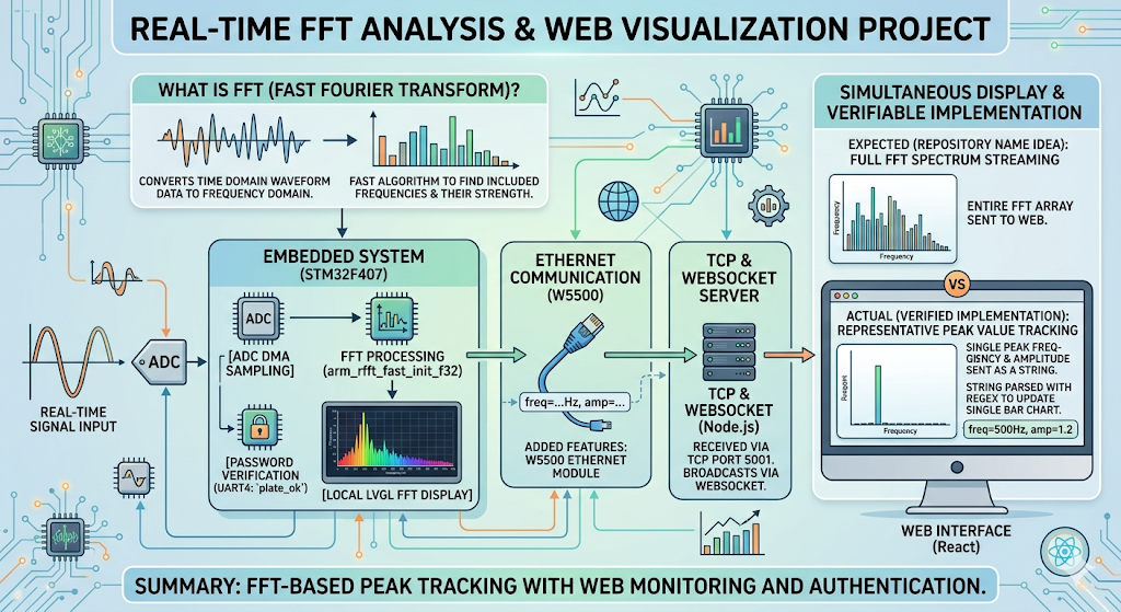
이 프로젝트는 임베디드 보드에서 실시간 신호를 샘플링하고, 그 신호가 어떤 주파수 성분으로 이루어져 있는지를 분석해 화면과 웹에서 동시에 확인할 수 있도록 만든 예제입니다. 이때 사용되는 FFT(Fast Fourier Transform) 는 시간축으로 들어온 파형 데이터를 주파수 영역으로 변환해, 어떤 주파수 대역이 얼마나 강한지 빠르게 계산하는 알고리즘입니다. 쉽게 말씀드리면, 입력 신호 안에 어떤 주파수가 포함되어 있는지를 찾아내는 과정이라고 보시면 됩니다.
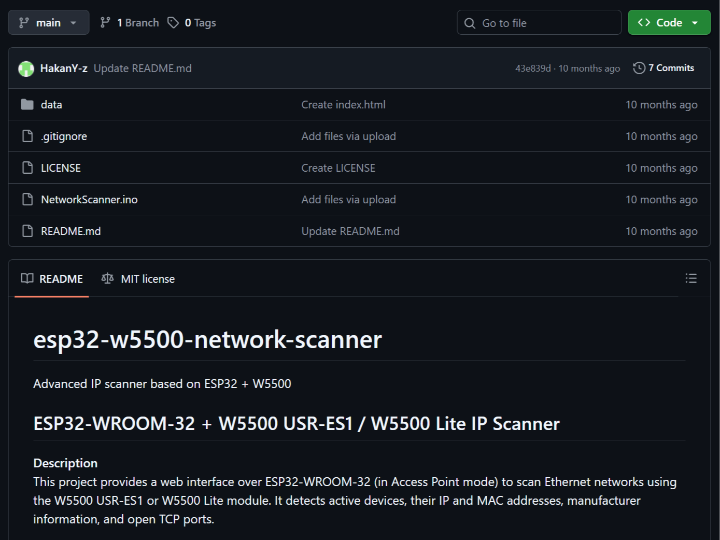
저장소 README에는 STM32F407 + LVGL 기반 FFT 표시 프로젝트를 확장하여 W5500 이더넷 모듈, React 기반 웹 인터페이스, 그리고 비밀번호 검증 절차를 추가했다고 설명되어 있습니다. 실제 User/main.c에서도 ADC DMA 시작, arm_rfft_fast_init_f32() 호출, LVGL 초기화, UART4 기반 인증 변수 plate_ok 확인이 한 실행 흐름 안에 묶여 있습니다.
다만 저장소 이름만 보면 전체 FFT 배열이 웹으로 그대로 전달될 것처럼 보일 수 있지만, 확인 가능한 구현은 현재 피크 주파수와 피크 진폭 한 쌍을 문자열로 전송하는 방식에 더 가깝습니다. User/main.c는 freq=...Hz, amp=... 형식으로 메시지를 만들고, tcp/tcp_server.js는 이를 TCP 5001 포트에서 받아 WebSocket으로 브로드캐스트하며, React 앱은 그 문자열을 정규식으로 파싱해 단일 막대 차트를 갱신합니다. 즉 현재 검증 가능한 구현은 “FFT 전체 스펙트럼 스트리밍”보다는 “대표 피크값 추적 및 웹 표시”라고 보는 편이 정확합니다.
이미지 출처 : AI 생성
Where WIZnet Fits
이 프로젝트에서 사용된 WIZnet 제품은 W5500입니다. W5500은 하드와이어드 TCP/IP 스택, 최대 80MHz SPI 인터페이스, 8개 독립 소켓, 32KB 내부 메모리를 제공하는 이더넷 컨트롤러입니다. 이런 구조 덕분에 외부 MCU는 네트워크 스택을 깊게 직접 구현하기보다 소켓 기반으로 이더넷 기능을 붙일 수 있습니다.
이 저장소에서도 W5500의 역할은 분명합니다. User/main.c에서는 시스템 초기화 직후 W5500_Init()을 호출하고, 이후 소켓 상태가 SOCK_ESTABLISHED일 때 FFT 결과를 send()로 내보냅니다. 즉 W5500은 FFT 계산 자체를 하는 부품이 아니라, STM32가 만든 결과를 외부 네트워크로 안정적으로 전달하는 유선 전송 엔진으로 배치되어 있습니다. ADC DMA, FFT, LVGL 화면 처리까지 이미 STM32가 수행하고 있기 때문에, 이런 분리는 구조상도 자연스럽습니다.
Implementation Notes
저장소에서 가장 먼저 확인되는 핵심 경로는 User/main.c입니다.
// User/main.c
W5500_Init();
...
if (fft_ready && getSn_SR(SOCK_TCPC) == SOCK_ESTABLISHED)
{
    sprintf(fft_msg, "freq=%.2fHz, amp=%.2f\r\n", fft_max_freq, fft_max_val);
    send(SOCK_TCPC, (uint8_t *)fft_msg, strlen(fft_msg));
}
이 코드는 두 가지를 분명하게 보여줍니다. 첫째, W5500 초기화가 ADC와 FFT 초기화 흐름 안에 실제로 포함되어 있습니다. 둘째, 웹으로 전달되는 데이터 포맷이 “주파수 1개 + 진폭 1개” 문자열이라는 점입니다. 따라서 이 저장소를 기반으로 확장하실 때는, 데이터 구조를 바꾸면 STM32 쪽뿐 아니라 Node 브리지와 React 파서도 함께 수정하셔야 합니다.
W5500 드라이버 초기화 쪽은 W5500/MyUDP.c에서 확인됩니다.
// W5500/MyUDP.c
W5500_Restart();
reg_wizchip_cs_cbfunc(W5500_Select, W5500_Unselect);
reg_wizchip_spi_cbfunc(W5500_ReadByte, W5500_WriteByte);
ctlnetwork(CN_SET_NETINFO, (void*)&gSetNetInfo);
이 부분은 W5500을 단순 SPI 주변장치가 아니라 실제 네트워크 인터페이스로 올리는 단계입니다. RESET 핀으로 칩을 재시작하고, 칩 선택과 SPI 바이트 입출력 콜백을 등록한 뒤, 네트워크 정보를 적용합니다. 이어서 같은 파일에서는 W5500의 채널 버퍼를 초기화하는 코드도 보이며, 이 프로젝트가 W5500을 단순 예제 수준이 아니라 실제 통신 경로로 사용하고 있음을 알 수 있습니다.
웹 연동 경로도 저장소 안에서 이어집니다. tcp/tcp_server.js는 TCP 5001 포트로 들어온 문자열을 받아 WebSocket 8765로 전달하고, my-react-app/src/App.jsx는 ws://localhost:8765에 접속해 freq=...Hz, amp=... 패턴을 정규식으로 파싱합니다. 다시 말씀드리면, 현재 구조는 “STM32 → W5500 → TCP 서버 → WebSocket → React”의 직렬 파이프라인입니다.
배선 측면에서도 확인 가능한 정보가 있습니다. User/main.c에는 W5500 인터럽트 핀으로 PG8, 칩 셀렉트 핀으로 PG9, 리셋 핀으로 PG15가 정의되어 있습니다. 따라서 실제 보드 적용 시에는 SPI 배선만 맞추는 것으로 끝나지 않고, CS/RESET/INT 핀 매핑까지 정확히 맞추셔야 초기화 실패를 줄일 수 있습니다.
Practical Tips / Pitfalls
- 이 저장소는 W5500을 실제 전송 경로에 포함시키고 있으므로, 가장 먼저
W5500_Init()호출이 정상적으로 지나가는지부터 확인하시는 편이 좋습니다. 초기화가 되지 않으면 이후 FFT 전송 로직은 모두 무의미해집니다. - 현재 웹 파서는
freq=...Hz, amp=...형식에 강하게 의존합니다. 메시지 포맷을 JSON이나 CSV로 바꾸실 경우 React 쪽 정규식 처리도 함께 수정하셔야 합니다. - TCP 서버와 WebSocket 서버는 각각 5001, 8765 포트를 사용합니다. STM32만 맞추고 PC 측 브리지를 실행하지 않으면 브라우저에서는 아무 데이터도 보이지 않습니다.
- 인증 변수
plate_ok가 UI 생성 조건으로 걸려 있으므로, 화면이 뜨지 않을 때는 네트워크보다 먼저 인증 경로가 막혔는지 확인하시는 것이 좋습니다. - W5500은 8개 독립 소켓과 내부 Tx/Rx 버퍼를 제공하므로, 향후 확장 시에는 측정 데이터, 제어 명령, 로그 채널을 분리하는 구조도 고려해 보실 수 있습니다.
FAQ
Q1. 왜 이 프로젝트에 W5500을 쓰는 것이 적절한가요?
A1. 이 프로젝트는 MCU가 ADC DMA, FFT 계산, LVGL 화면 갱신을 동시에 수행합니다. 이런 상황에서는 네트워크 스택을 MCU 내부에 더 많이 얹기보다, W5500처럼 하드와이어드 TCP/IP와 소켓 인터페이스를 제공하는 이더넷 컨트롤러로 전송 계층을 분리하는 편이 구조를 단순하게 유지하기 좋습니다.
Q2. STM32F407과는 어떤 방식으로 연결되나요?
A2. 저장소에서 확인되는 제어 핀은 PG8(INT), PG9(CS), PG15(RESET)입니다. 그리고 드라이버 쪽에서는 reg_wizchip_cs_cbfunc()와 reg_wizchip_spi_cbfunc()를 통해 보드의 GPIO/SPI 함수를 W5500 드라이버와 연결합니다. 즉 실제 연결은 SPI 기반이며, 보드 레벨 핀 제어가 함께 필요합니다.
Q3. 이 프로젝트 안에서 W5500이 맡는 구체적인 역할은 무엇인가요?
A3. W5500은 STM32가 계산한 FFT 결과를 문자열로 외부에 전달하는 역할을 합니다. 메인 루프에서 소켓이 연결된 상태일 때 freq=...Hz, amp=... 메시지를 send()로 보내고, 이후 PC의 TCP 서버와 React 앱이 이를 받아 웹에 표시합니다. 즉 W5500은 “계산기”가 아니라 “유선 데이터 전달 계층”입니다.
Q4. 초보자도 따라 해볼 수 있을까요?
A4. 완전 초보자보다는 중급 이상 개발자에게 더 적합해 보입니다. STM32 HAL, DMA, CMSIS-DSP FFT, LVGL, W5500 초기화, Node 서버, React 프런트엔드가 모두 연결되어 있기 때문입니다. 다만 저장소 구조가 User/, W5500/, tcp/, my-react-app/으로 비교적 분리되어 있어, 한 번에 전부 보지 않고 단계별로 따라가시면 이해하기는 수월한 편입니다.
Q5. Wi-Fi 모듈이나 MCU 내부 소프트웨어 스택과 비교하면 어떤 차이가 있나요?
A5. 이 저장소는 실시간 계측과 화면 처리가 이미 무거운 편이기 때문에, 유선 이더넷 전송을 별도 컨트롤러로 나누는 방향이 잘 맞습니다. W5500은 하드와이어드 TCP/IP, SPI 인터페이스, 8개 독립 소켓, 내부 버퍼를 제공하므로 MCU는 측정과 UI에 더 집중할 수 있습니다. 반면 Wi-Fi나 MCU 내부 스택은 무선 관리나 스택 통합 부담이 더 커질 수 있어, 이 프로젝트처럼 계측 중심 구조에서는 설계 복잡도가 달라질 수 있습니다.
What the Project Does
This project is an example of sampling a real-time signal on an embedded board, analyzing which frequency components are present in that signal, and showing the result on both a local display and a web interface. The FFT used here, or Fast Fourier Transform, is an algorithm that converts waveform data from the time domain into the frequency domain so the system can quickly calculate how strong each frequency band is. In simple terms, it is the process of identifying which frequencies are contained in the input signal.
According to the repository README, this project extends an STM32F407 + LVGL-based FFT display project by adding a W5500 Ethernet module, a React-based web interface, and a password verification step. In the actual User/main.c implementation, ADC DMA start-up, the arm_rfft_fast_init_f32() call, LVGL initialization, and the UART4-based authentication variable plate_ok are all tied into the same execution flow.
At first glance, the repository name may suggest that the entire FFT array is transmitted directly to the web interface. However, the implementation that can actually be verified is closer to sending a single pair of values: the peak frequency and the peak amplitude as a string. User/main.c formats the message as freq=...Hz, amp=..., tcp/tcp_server.js receives it on TCP port 5001 and broadcasts it over WebSocket, and the React app parses the string with a regular expression to update a single bar chart. In other words, the implementation currently verified is more accurately described as peak-value tracking and web visualization rather than full FFT spectrum streaming.
Image source: AI-generated
Where WIZnet Fits
The WIZnet product used in this project is the W5500. The W5500 is an Ethernet controller that provides a hardwired TCP/IP stack, an SPI interface up to 80 MHz, 8 independent sockets, and 32 KB of internal memory. Because of this architecture, the external MCU does not need to implement a full network stack in depth and can instead add Ethernet functionality through a socket-based interface.
Its role is also clear in this repository. In User/main.c, W5500_Init() is called immediately after system initialization, and the FFT result is transmitted with send() when the socket state becomes SOCK_ESTABLISHED. This means the W5500 is not responsible for FFT computation itself. Instead, it is used as a wired transport engine that reliably sends the result generated by the STM32 to the external network. Since the STM32 is already handling ADC DMA, FFT processing, and LVGL rendering, this division of responsibility is structurally appropriate.
Implementation Notes
One of the first key paths visible in the repository is User/main.c.
// User/main.c
W5500_Init();
...
if (fft_ready && getSn_SR(SOCK_TCPC) == SOCK_ESTABLISHED)
{
    sprintf(fft_msg, "freq=%.2fHz, amp=%.2f\r\n", fft_max_freq, fft_max_val);
    send(SOCK_TCPC, (uint8_t *)fft_msg, strlen(fft_msg));
}
This code clearly shows two things. First, W5500 initialization is actually part of the same flow as ADC and FFT initialization. Second, the data format sent to the web side is a string containing one frequency value and one amplitude value. As a result, if you expand this project further and change the data structure, you will need to update not only the STM32 firmware but also the Node bridge and the React parser.
The W5500 driver initialization can be seen in W5500/MyUDP.c.
// W5500/MyUDP.c
W5500_Restart();
reg_wizchip_cs_cbfunc(W5500_Select, W5500_Unselect);
reg_wizchip_spi_cbfunc(W5500_ReadByte, W5500_WriteByte);
ctlnetwork(CN_SET_NETINFO, (void*)&gSetNetInfo);
This is the stage where the W5500 is brought up not merely as an SPI peripheral, but as a real network interface. The chip is restarted through the RESET pin, chip-select and SPI byte I/O callbacks are registered, and the network information is applied. The same file also contains code for initializing the W5500 channel buffers, which shows that this project uses the W5500 as an actual communication path rather than as a minimal example.
The web integration path also continues inside the repository. tcp/tcp_server.js receives a string on TCP port 5001 and forwards it to WebSocket port 8765, while my-react-app/src/App.jsx connects to ws://localhost:8765 and parses the freq=...Hz, amp=... pattern with a regular expression. In other words, the current structure is a serial pipeline of STM32 → W5500 → TCP server → WebSocket → React.
There is also verifiable wiring information. In User/main.c, the W5500 interrupt pin is defined as PG8, the chip-select pin as PG9, and the reset pin as PG15. Therefore, in an actual hardware setup, it is not enough to match only the SPI wiring. The CS, RESET, and INT pin mapping must also be correct to reduce initialization failures.
Practical Tips / Pitfalls
- Since this repository includes the W5500 in the actual transmission path, it is best to first confirm that
W5500_Init()completes normally. If initialization fails, the FFT transmission logic that follows becomes meaningless. - The current web parser strongly depends on the
freq=...Hz, amp=...message format. If you change the message format to JSON or CSV, you will also need to update the React-side parsing logic. - The TCP server and WebSocket server use ports 5001 and 8765 respectively. If only the STM32 side is configured and the PC-side bridge is not running, no data will appear in the browser.
- Because the authentication variable
plate_okis used as a condition for UI creation, if the display does not appear, it is better to check whether the authentication path is blocked before debugging the network path. - The W5500 provides 8 independent sockets and internal Tx/Rx buffers, so future extensions could separate measurement data, control commands, and log channels into different paths.
FAQ
Q1. Why is the W5500 a suitable choice for this project?
A1. This project requires the MCU to handle ADC DMA, FFT computation, and LVGL screen updates at the same time. In this kind of system, it is often better to separate the transport layer with an Ethernet controller such as the W5500, which provides a hardwired TCP/IP stack and a socket interface, rather than placing more of the network stack inside the MCU. This helps keep the overall structure simpler.
Q2. How is it connected to the STM32F407?
A2. The control pins confirmed in the repository are PG8 for INT, PG9 for CS, and PG15 for RESET. On the driver side, reg_wizchip_cs_cbfunc() and reg_wizchip_spi_cbfunc() connect the board-level GPIO and SPI functions to the W5500 driver. In other words, the actual connection is SPI-based, but board-level pin control is also required.
Q3. What exactly does the W5500 do in this project?
A3. The W5500 sends the FFT result generated by the STM32 to the outside as a string. In the main loop, when the socket is connected, the firmware sends a freq=...Hz, amp=... message with send(), and the PC-side TCP server and React app then display it on the web interface. So the W5500 is not the “calculator” in this system. It is the wired data transport layer.
Q4. Can beginners follow this project?
A4. It appears more suitable for intermediate-level developers than complete beginners. The project combines STM32 HAL, DMA, CMSIS-DSP FFT, LVGL, W5500 initialization, a Node server, and a React frontend. However, the repository is organized into relatively separate directories such as User/, W5500/, tcp/, and my-react-app/, so it is still manageable if you follow the structure step by step instead of trying to understand everything at once.
Q5. How does it compare with a Wi-Fi module or an MCU-internal software stack?
A5. This repository is already fairly heavy in terms of real-time measurement and display handling, so separating wired Ethernet transport into a dedicated controller is a reasonable design choice. The W5500 provides a hardwired TCP/IP stack, an SPI interface, 8 independent sockets, and internal buffers, which allows the MCU to focus more on measurement and UI tasks. In contrast, Wi-Fi modules or MCU-internal software stacks may introduce additional wireless management or integration overhead, which can increase design complexity in a measurement-oriented project like this.
-
Github Code
