As a Enginneer, I always work in the office to handle a lot of documentation and programming in front of the computer or monitor. There always have a time that I have lost track on my work that causes putting too much of time on job and forget to take some rest.
Thus, I had tried to make an application to monitor my screen time with my PC to check my screening time.
This application should helped me a lot of manage my time to allow me to take care with my eye.
This is just a simple application to work with my application based on W5100S-EVB-PICO and Adafruit IO in circuitpython.
The HLK-LD2410B human detection sensor module that I'm using has a lot of features to allow you to develop different kinds of application. For this applicaiton, I could upgrade it to have a security feature to prevent someone else is using my PC.
For details, please refer to the information below.
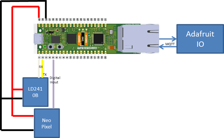
Structure:
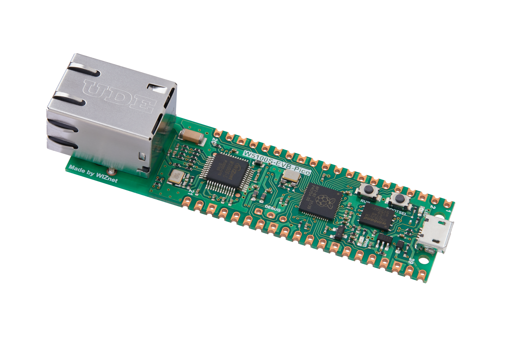
As you see from the image above, this application is a simple application that only required two modules with a W5100S-EVB-PICO to mange the data for delivering important information to the Adafruit IO.
The first module is the most important module for this application. The Human detection sensor module (HLK-LD2410B) has the ability to determine and differentiate a moving object and a stable object distance with the sensor. This information will send in a standard formatted byte string through UART.
The next module is a WS2812 LED lights (Neopixel library compatiable) that I found from the internet. It will display in different kind of colors to alert me to leave the PC and take some rest.
Programming - Human Detection sensor
For communicating with this module using UART, it is a complicated job for me. However, the user manaul and the help of ChatGPT had helped a lot on this issue.
They provide good guidelines and description for me to have a better understanding of this module and making codes in different kind way.
The followings are the library's functions that I had made for this module to fulfill the usage for this application.
1. Collect Data - Change those Byte information into meaningful information to Adafruit IO and used for displaying the LED status.
2. Send commands - Sending commands to the module and make some modification to the module.
3. Search and identfy data - Find those data using head and tail of the data set and send it to the above application for analysis
Progamming - Collect data
Collecting data is simple to handle. I just need to found the data from my module and collect the correct part of information from those data.
All those data will be converted back into integers and saved in each variables to allow my W5100S-EVB-PICO could be used for further operation or devliery it to Adafruit IO.
Codes
def collect_data (self, timeout: int = 5) -> None:
        self.uart.reset_input_buffer()
        gc.collect()
        stamp = time.monotonic()
        response = b""
        while (time.monotonic() - stamp) < timeout:
            if self.uart.in_waiting:
                response += self.uart.read(1)
                if Out_head in response and response[-4:] == Out_end:
                    break
        #print(response)

        #check data mode headers
        self._check_head_tail("data",response)
        if response[7] != int.from_bytes(Out_data_head,'big'):
            raise ValueError ("Wrong Output data Header")
        elif response[-6] != int.from_bytes(Out_data_end,'big'):
            raise ValueError ("Wrong Output data End")
        elif response[-5] != 0:
            raise ValueError ("Wrong checking point")

        #Checking operation Mode
        if response[6] == 2:
            self.W_type = "Basic Mode"
        elif response[6] == 1:
            self.W_type = "Engineering Mode"
        else:
            raise ValueError ("Wrong Working mode Data")

        #Checking target:
        if response[8] == 0:
            self.target = "No target"
        elif response[8] == 1:
            self.target = "Moving target"
        elif response[8] == 2:
            self.target = "Stable target"
        elif response[8] == 3:
            self.target = "Both target"
        else:
            raise ValueError ("Wrong Rarget Value")

        #Convert all the data
        self.move_dist = response[10]*256 + response[9]
        self.move_sen = response[11]
        self.stable_dist = response[13]*256 + response[12]
        self.stable_sen = response[14]
        self.M_dist = response[16]*256 + response[15]
Programming - Send commands
This modules has a lot of commands to be set. Like controlling the bluetooth of this module, setting the sensitivity of the module or operting in engineer mode for this application.
Since my application is a simple application, it does not required those specific settings to provide a very accurate information.
Thus, I just select some of the commands that is required for my application.
1. On/ Off command mode - This module required the user to send out a set of command to alert the module to change into command mode to handle different kinds of command.
Codes
@property
    def cmd_mode(self): #check the command mode is it on / off
        return self.cmd_check # 0 = OFF , 1 = ON

    @cmd_mode.setter #set the command mode
    def cmd_mode(self, value):
        #Set the codes into correct format before send
        if value == 1:
            data = Command_head + self._shifting(4) +Command_mode_on + Command_end
        elif value == 0:
            data = Command_head + self._shifting(2) +Command_mode_off + Command_end

        result =self._send_command(data) #send the data to the module

        #Received feedback - Print out the result and change the command mode staus
        if result[0] == Command_mode_on[0]:
            print("Command Mode ON")
            self.cmd_check = 1
        elif result[0] == Command_mode_off[0]:
            print("Command Mode OFF")
            self.cmd_check = 0
2. Set Sensitivty - For my applicaton, it is required me to set the sensitivity for each distance units. By setting these information, I could set the sensor to focus on specific distance.
Codes
def set_sensitivity(self,unit_sen: str, move_sen: int, stable_sen: int):
        padding = b"\x00\x00"
        move = b"\x01\x00"
        stable = b"\x02\x00"
        try:
            unit = self._shifting(int(unit_sen))

        except ValueError as error:
            if unit_sen is "all":
                unit = b"\xFF\xFF"
            else:
                raise ValueError ("Wrong sensitivity Input")

        except Exception as error:
            raise error

        data = Command_head + self._shifting(20) + sensitivity + padding + unit + padding
        data = data + move + self._shifting(move_sen) + padding
        data = data + stable + self._shifting(stable_sen) + padding + Command_end

        result =self._send_command(data)

        print ("Sensitivity has been Set!")
3. Send command and collect responses - This section is used to organize all commands into one standard function. It will help me send those commands and collects the response message and return it back to each commands for further analysis.
Codes
def _send_command (self,cmd: str, timeout: int = 5) -> None:
        #print(cmd)
        self.uart.write(cmd)

        self.uart.reset_input_buffer()
        gc.collect()
        stamp = time.monotonic()
        response = b""
        while (time.monotonic() - stamp) < timeout:
            if self.uart.in_waiting:
                response += self.uart.read(1)
                if Command_head in response and response[-4:] == Command_end:
                    break
        #print(response)
        #print(type(response))

        self._check_head_tail("command",response)
        if response[6] + response[7] != cmd[6] + cmd[7] + 1:
            raise ValueError("Command Word Response Error")
        elif response[8] + response[9] != 0:
            raise ValueError("Command Fail")

        return response[6:-4]
Programming - Search and identfy data
The most complication data handling is finding the those data from the load of information provided by the module.
As I mentioned previously, this module will automatically send out the data to W5100S-EVB-PICO. I need to collect the correct data from the UART buffer and converted into correct information.
Thus, checking those data based on header and tails are the best way to easily find those information. I had even added check points to ensure those information are correct and return the core information for further progress.
The main code is simple. I had used WIZnet's Adafruit IO reference code to alllow me easily to communicate with Adafruit IO using W5100S-EVB-PICO.
For organize the between the module and what kind of information will be uploaded to Adafruit IO will shows as follow.
1. Detect are there any person in front of the sensor
2. Repeating Number 1 until it has any condition change
a) Cannot detect anyone in front of the screen
b) Waited for a long time
3. If any above condition has activated, it will handle in
a) Get the leaving time and compare the waited time and reset all variables
b) Showed in Red light and upload alert to Adafruit
3. The waiting time will be handled and set by Adafruit IO.
- It includes a reset button to reset all the variables
Codes:
#function to collect the screen time from adafruit IO
def waiting_time(client, topic, message):
    global time_recorder
    # Method callled when a client's subscribed feed has a new value.
    print("New message 2 on topic {0}: {1}".format(topic, message))
    time_recorder = int(message)

#function to collect reset response from adafruit IO
def reset(client, topic, message):
    # Method callled when a client's subscribed feed has a new value.
    print("New message on topic {0}: {1}".format(topic, message))
    if message == "0":
        flag.value = 1

#Main function to manage the screen time operation
def scan(time_value,temp,counter,alert_counter,leave, led):
    global time_recorder

    #collect data function from LD2410B module library
    dist_sen.collect_data()
    #check the sensor's targetting object
    if dist_sen.target == "Both target":
        if dist_sen.move_dist >= dist_sen.stable_dist: #compare the distance - distance value is more accurate
            data = dist_sen.move_dist
        else:
            data = dist_sen.stable_dist
    elif dist_sen.target == "Moving target": #If it detects the moving object, choose moving target
        data = dist_sen.move_dist
    elif dist_sen.target == "Stable target": #Since the distance between the module is short, stable target could be consider to use.
        data = dist_sen.stable_dist
        if data == 8: #if it shows 8 value, it means error.
            data = dist_sen.move_dist
    else:
        data = None # No target, just ignore

    if data != None
        # the range that I will be seated - If detected
        if data > 65 and data < 100:
            leave = False # Turn off leave flag
            temp = time.time() #collect current time
            if time_value is None:
                time_value = temp # Starting Point
            else: #check current status for LED display
                difference = temp - time_value
                if difference <= (time_recorder /3): #Beginning period with the screen
                    print ("Green Light")
                    pixels.fill((38,252,5)) # Display green light
                    pixels.show()
                    led += 1
                    if led == 1: #Upload once to adafruit IO
                        io.publish("light", "#26fc05") #Upload green light status
                elif difference > (time_recorder /3) and difference < time_recorder: #it has been for a while with the screen
                    print ("Yellow Light")
                    if led >= 1:
                        led = 0
                    pixels.fill((250,242,7)) # Display Yellow Light
                    pixels.show()
                    led -= 1
                    if led == -1: #Upload once to adafruit IO
                        io.publish("light", "#faf207")
                elif difference >= time_recorder: #If it has passed or equal to the waiting time
                    print("Over time! - Red Light")
                    alert_counter += 1
                    if alert_counter == 1: #Activate the alert section
                        io.publish("alert", "OverTime") #posted to adafruit IO to show it has passed the screening time
                        io.publish("light", "#fc0905") #showed red on adafruit IO
                    pixels.fill((252,9,5)) # sDisplay Red Light
                    pixels.show()
        else: #detected No one is in front of the screen
            if leave is False: #confirmed the previous moments are present in front of the screen
                counter += 1
                if temp is not None: #if the previous moment is present in front of the screen
                    counter  = 0 #reset counter
                    temp = None
                print (counter)
                if counter > 3: #if accumulated for 3 times, confirmed no one is in front of the screen.
                    #reset everything
                    temp = time.time()
                    difference = temp - time_value
                    print ("You have looked on the screen for {} seconds".format(difference))
                    counter = 0
                    time_value = None
                    temp = None
                    alert_counter = 0
                    leave = True
                    led = 0
                    pixels.fill((0,0,0)) # set to turn off the pixel
                    pixels.show() #present to off
                    io.publish("light", "#000000")

    return time_value, temp, counter, alert_counter,leave,led
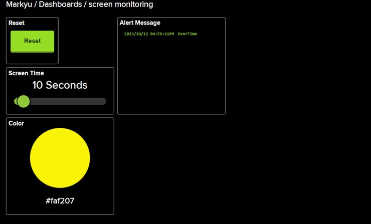
Results
The followings are the result from Adafruit IO and the display results on LED.
From the image above, it shows I had set a reset button to reset all the variables inside W5100S-EVB-PICO. It also includes Screen Time setup that is in seconds.
If you wanted to make it in a longer period, you could based on my codes to make your own changes. Please know that my codes is based on "Seconds" as the based unit for this code.
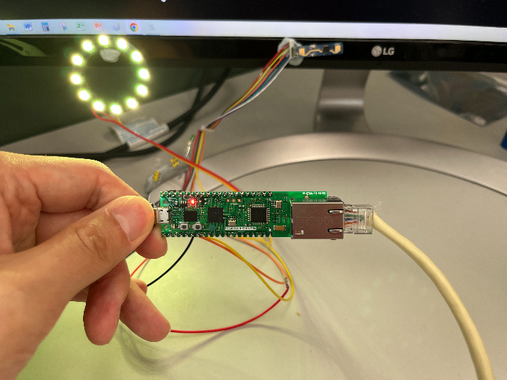
LED display in different condition:
LED off - The device has been reset or there is no one in front of the sensor
Green - The beginning stage of screen time.
Yellow - Screen time has been passed for a long period of time:
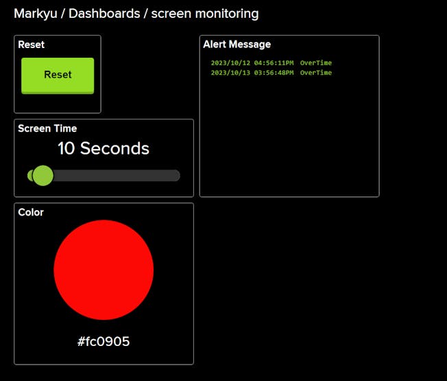
Red - It has passed the screen time and it sent alert to Adafruit IO
As you could see from the above images, it shows the application will provide different kind of LED to indicate me the screen time that I had been in front my computer.
This information will be uploaded to the color block that showed on Adafruit IO.
The alert message will also shows a "Overtime" message on alert message block to notify me.
YouTube:
Finally, I had made a simple YouTube demo based on this applcation.

 Software Apps and online services