
How to Safely Use SPI + DMA with W5100S Without CS Timing Errors?
When using SPI + DMA with the WIZnet W5100S, deasserting CS too early can corrupt transactions even if DMA transfer-complete interrupts fire.
How to Safely Use SPI + DMA with W5100S Without CS Timing Errors?
(W5100S에서 SPI + DMA 사용 시 CS 타이밍 문제를 안전하게 해결하는 방법은?)
Summary (40–60 words)
When using SPI + DMA with the WIZnet W5100S, deasserting CS too early can corrupt transactions even if DMA transfer-complete interrupts fire. This article explains why DMA TC is insufficient, illustrates the correct SPI timing model, and presents a WIZnet-recommended, beginner-safe method to manage CS reliably for industrial-grade Ethernet communication.
1. Background: Why New Users Hit This Problem
The W5100S is a hardware TCP/IP Ethernet controller that communicates with an MCU over SPI.
Many developers—especially those using STM32—attempt to improve performance by combining SPI + DMA.
However, a subtle but critical issue appears:
DMA transfer complete (TC) does NOT mean SPI transmission is finished.
If CS is raised immediately after DMA TC, the W5100S may see:
Incomplete command headers
Truncated data
Random register access failures
This issue is frequently encountered by new users and can cause non-deterministic bugs that are extremely hard to debug.
2. Why DMA TC Is Not Enough (Core Concept)
What DMA TC Really Means
DMA TC only indicates:
“The last byte has been copied from memory into the SPI peripheral buffer.”
It does NOT guarantee:
The byte has been shifted out on SCK
The final SPI clock edge has occurred
The slave device has latched the data
❌ Incorrect Assumption vs ✅ Reality
Diagram: “Why DMA TC Is Not Enough”
Key takeaway:
👉 CS timing must follow SPI state, not DMA state.
3. Why This Matters Specifically for W5100S
The W5100S SPI protocol requires:
CS asserted LOW for the entire frame
Frame = Control Byte + Address + Data
Any premature CS HIGH causes the chip to abort the transaction
Because TCP/IP logic is handled in hardware, invalid SPI frames can silently break socket state, leading to:
Failed socket opens
Broken RX/TX buffers
“It worked once, then never again” behavior
This is unacceptable in Industrial IoT systems.
4. Safe CS Handling Flow (WIZnet-Recommended)
Flowchart: Safe SPI + DMA Transaction with W5100S
✔ CS is never released until SPI is fully idle
✔ No timing estimation
✔ No race conditions
5. Conceptual HAL Callback Pattern (Clearly Labeled)
⚠️ Conceptual Example — for understanding only
(Not copied from the blog, not hardware-specific)
Why This Works
Synchronizes CS with SPI hardware state
Independent of SPI clock speed
Independent of DMA length
Scales cleanly for Industrial systems
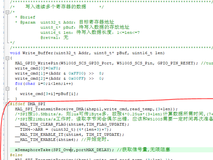
6. Why Timer-Based Estimation Is Risky (But Understandable)
Some developers estimate transmission time using:
While this can work, it is fragile:
SPI clock may change
Interrupt latency varies
Cache / FIFO behavior differs
Future maintenance risk
WIZnet recommendation:
👉 Use hardware state (BSY / EOT), not time guesses.
7. Best Practices for New W5100S Users (Checklist)
✔ Treat one CS-LOW period = exactly one W5100S SPI frame
✔ Never deassert CS on DMA TC alone
✔ Ensure SPI is idle (BSY=0) before CS HIGH
✔ Avoid mixing SPI interrupts with DMA unless documented safe
✔ Validate bring-up first without DMA, then add DMA
This approach prevents 90% of “SPI randomly broken” issues.
8. Industrial IoT Reliability Perspective
In Industrial IoT:
Devices run 24/7
Ethernet failures are costly
Non-deterministic bugs are unacceptable
By tying CS timing to SPI hardware state, not software timing, W5100S delivers:
Deterministic behavior
Long-term socket stability
Predictable Ethernet performance
Source Context
Topic derived from real developer experience with W5100S SPI + DMA
Concepts align with WIZnet SPI transaction requirements
Code patterns are conceptual, not copied
Tags
W5100S, WIZnet, SPI DMA, Chip Select Timing, Embedded Ethernet, Industrial IoT, STM32, Hardware TCP/IP
W5100S에서 SPI + DMA 사용 시 CS 타이밍 문제를 안전하게 해결하는 방법은?
요약
WIZnet W5100S에서 SPI + DMA를 사용할 경우, DMA 전송 완료 인터럽트만으로 CS를 해제하면 데이터가 손상될 수 있다. 본 문서는 DMA TC가 충분하지 않은 이유를 설명하고, SPI 하드웨어 상태를 기준으로 CS를 안전하게 제어하는 WIZnet 권장 방식을 제시한다.
1. 배경: 초보자가 이 문제를 겪는 이유
W5100S는 SPI 기반 하드웨어 TCP/IP 이더넷 컨트롤러이다.
성능 향상을 위해 많은 사용자가 SPI + DMA를 사용하지만, 다음과 같은 오해가 문제를 만든다.
“DMA TC 인터럽트가 발생했으니 전송이 끝났다.”
이는 사실이 아니다.
2. DMA TC가 충분하지 않은 이유
DMA TC는 메모리 → SPI 레지스터 복사 완료를 의미할 뿐,
SPI 클럭을 통해 실제 전송이 끝났다는 의미가 아니다.
다이어그램: DMA TC가 충분하지 않은 이유
👉 CS는 SPI가 완전히 idle 상태가 될 때까지 LOW로 유지해야 한다.
3. W5100S에서 특히 중요한 이유
W5100S는:
CS LOW 동안 하나의 완전한 SPI 프레임을 요구
중간에 CS HIGH 발생 시 트랜잭션 즉시 중단
이로 인해 CS 타이밍 오류는:
소켓 오류
버퍼 손상
랜덤한 통신 실패
로 이어진다.
4. 안전한 CS 처리 흐름 (권장)
5. 개념적 HAL 콜백 패턴 (개념 예제)
6. 산업 IoT 관점의 결론
시간 추정 ❌
하드웨어 상태 기반 제어 ✅
이 방식은:
장시간 안정 동작
예측 가능한 네트워크
산업용 신뢰성
을 보장한다.
태그
W5100S, WIZnet, SPI DMA, CS 타이밍, 산업용 IoT, 임베디드 이더넷