



How to Port W6300 IPv6 Networking to STM32H7 and STM32F4?
The source article demonstrates the intended structure of STM32F4 + WIZnet W6100 IPv6/UDP communication, but its code is explicitly presented as an example fram
How to Port W6300 IPv6 Networking to STM32H7 and STM32F4?
Summary
The source article demonstrates the intended structure of STM32F4 + WIZnet W6100 IPv6/UDP communication, but its code is explicitly presented as an example framework and relies on placeholder register-access functions rather than a complete driver. For a commercial implementation, the stronger path is STM32H7 or a QSPI-capable STM32F4 + W6300 + WIZnet ioLibrary_Driver. W6300 supplies hardwired IPv4/IPv6 TCP/IP processing, eight hardware sockets, 64 KB of socket memory, and a four-data-line QSPI host interface, while the MCU firmware is divided into a thin W6300 bus port, network initialization, socket services, and application logic.
What the Project Does
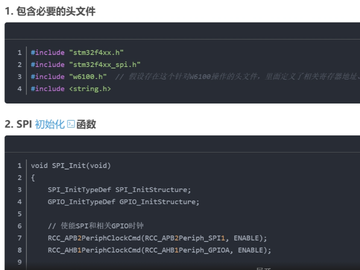
The CSDN source is titled “STM32F4 中集成 W6100 实现 IPv6 通信” and presents an STM32F4/W6100 UDP-over-IPv6 example. It configures SPI1 as an 8-bit, MSB-first master using PA5/PA6/PA7, then sketches W6100 initialization, IPv6 configuration, UDP transmission, UDP reception, and a simple main() sequence.
Its basic architectural intent is:
STM32F4 application → SPI → W6100 → hardware IPv6/UDP → Ethernet
The article shows this initialization concept:
Write_W6100_Reg(MODE_REG, MODE_IPV6);

uint8_t mac_address[6] =
    {0x00, 0x08, 0xdc, 0x12, 0x34, 0x56};

Write_W6100_Reg(SHAR_REG, mac_address, 6);
Write_W6100_Reg(SIPR_REG, ipv6_address, 16);
The important limitation is stated by the article itself: functions such as Write_W6100_Reg(), Write_W6100_Data(), Trigger_W6100_Send(), and Check_W6100_UDP_Data_Arrived() are assumed helper functions and require a real implementation based on the device documentation. The article also describes itself as an example framework that needs further completion.
That makes it useful for understanding the desired layers, but not as production-ready firmware.
There is another architectural issue to correct before using the example commercially. The article manually constructs an eight-byte UDP header before writing payload bytes. With W6100 or W6300 operating in their normal hardwired UDP socket modes, the application should ordinarily use the WIZnet socket abstraction and let the hardware network engine generate the UDP/IP headers. WIZnet's current ioLibrary supports dedicated IPv4, IPv6, and dual-stack socket modes, including UDP6 and dual UDP operation.
For a new product, the cleaner architecture is therefore:
Application
↓
TCP/UDP service layer
↓
WIZnet ioLibrary socket API
↓
W6300 register/socket driver
↓
STM32 QSPI + DMA port
↓
W6300 hardwired IPv4/IPv6 engine
↓
10/100 Ethernet
This separation matters commercially because MCU migration then affects primarily the lowest bus layer rather than the complete networking application.
Where WIZnet Fits
The proposed controller for the new design is the WIZnet W6300.
W6300 integrates the Ethernet MAC, 10/100 PHY, and a hardwired dual IPv4/IPv6 networking engine. It provides eight independent hardware sockets and 32 KB TX plus 32 KB RX memory, for 64 KB total socket SRAM. WIZnet's current product table reports network performance up to 91 Mbps, measured using iPerf.
The important upgrade from the original W6100-style STM32 example is the host interface.
W6300 supports:
CSn + SCLK + QD0 + QD1 + QD2 + QD3
in Quad-SPI mode. The datasheet defines Single, Dual, and Quad variants under the QSPI host interface, with SPI modes 0 and 3. Its current SPI timing table specifies a maximum SCLK of 75 MHz.
At 75 MHz in four-bit data mode, the raw data phase can theoretically move:
75 MHz × 4 bits = 300 Mbit/s
before QSPI instruction, address, control, dummy phases, transaction gaps, DMA setup, socket access, and MCU processing are included.
That does not mean the product will achieve 300 Mbit/s Ethernet throughput; the PHY remains 100BASE-TX. It does mean that for large sequential transfers, properly implemented Quad-SPI is wide enough that the host bus need not automatically become the limiting link before the Ethernet interface.
For a commercial STM32 design, this makes the W6300 particularly relevant when the MCU must simultaneously perform other work such as sensing, motor control, protocol conversion, storage, UI processing, encryption, or fieldbus communication. TCP/UDP protocol state, retransmission, ARP, IPv4/IPv6 handling, and socket buffering remain in the Ethernet controller rather than becoming another large MCU software subsystem.
STM32F4 Target
WIZnet now publishes an official STM32F412ZG + W6300 reference project. It uses the STM32 hardware QUADSPI peripheral and connects:
| Function | STM32F412ZG | W6300 |
|---|---|---|
| QSPI CLK | PB2 | SCLK |
| QSPI NCS | PB6 | CSn |
| QSPI IO0 | PC9 | QD0 |
| QSPI IO1 | PC10 | QD1 |
| QSPI IO2 | PC8 | QD2 |
| QSPI IO3 | PA1 | QD3 |
| Reset | PC0 | RSTn |
| Interrupt | PC1 | INTn |
The repository uses STM32 HAL, ioLibrary_Driver, a dedicated wizchip_qspi.c/.h port layer, and examples covering DHCP/DNS, TCP/UDP loopback, multi-socket TCP, HTTP, MQTT, SNTP, TFTP, TLS, and other network functions.
This is the recommended baseline for an STM32F4 reference port.
Not every STM32F4 device exposes the same QUADSPI hardware. The specific F4 part must therefore be selected before copying the F412 bus layer. If the selected MCU lacks a suitable QSPI peripheral, W6300 can operate in Single-SPI mode, but that gives up much of the reason for pairing W6300 with a performance-oriented MCU.
STM32H7 Target
For STM32H7, the recommended software boundary remains identical:
ioLibrary_Driver → W6300 QSPI callbacks → STM32 HAL
Only the MCU-specific bus layer changes.
On an H7 device with QUADSPI, the F412 implementation can be ported from HAL_QSPI_* to the equivalent H7 HAL calls. On H7 variants that use OCTOSPI instead, the transport layer should be implemented with the corresponding OCTOSPI indirect command/read/write API while retaining the same WIZnet callback boundary.
This architecture avoids maintaining separate TCP/IP application codebases for F4 and H7.
A practical source tree is:
Core/
    main.c

port/
    wizchip_qspi.c
    wizchip_qspi.h

network/
    network_init.c
    network_init.h
    socket_service.c
    socket_service.h

Libraries/
    ioLibrary_Driver/
port/ changes between STM32F4 and STM32H7. The socket and application layers should remain largely MCU-independent.
Implementation Notes
The original CSDN code should be treated as a conceptual W6100/IPv6 example rather than the starting driver for the commercial product. Its own text states that the register and data functions are hypothetical and need implementation.
For W6300, WIZnet's official STM32F412 repository provides a stronger reference.
QSPI/DMA transfer strategy
Source: STM32F412-W6300-SoM-C/port/wizchip_qspi.c, around lines 801 and 958–1047.
#define QSPI_DMA_THRESHOLD 16

if (len >= QSPI_DMA_THRESHOLD)
{
    g_qspi_tx_done = 0;
    HAL_QSPI_Transmit_DMA(&hqspi, pbuf);

    while (!g_qspi_tx_done)
        ;
}
else
{
    HAL_QSPI_Transmit(&hqspi, pbuf, 1000);
}
The implementation deliberately uses a hybrid polling/DMA model: small transfers remain polling-based because DMA setup can cost more than it saves, while larger transfers use DMA. The repository sets the initial crossover point at 16 bytes and explicitly recommends benchmarking the threshold.
This is a good pattern for both STM32F4 and STM32H7.
Register reads are often short and latency-sensitive; bulk socket-buffer transfers benefit much more from DMA.
For a commercial H7 port, the same structure should be retained, but an additional issue becomes important if the Cortex-M7 data cache is enabled: DMA buffers need a defined cache-coherency policy. Network TX buffers may require cache cleaning before DMA reads them, and RX buffers may require invalidation before the CPU consumes DMA-written data. Buffer placement also needs to use SRAM that the selected DMA peripheral can actually access.
W6300/ioLibrary initialization
Source: STM32F412-W6300-SoM-C/port/wizchip_qspi.c, around lines 1080–1135.
reg_wizchip_qspi_cbfunc(
    W6300_QspiReadByte,
    W6300_QspiWriteByte);

uint8_t memsize[2][8] = {
    {2,2,2,2,2,2,2,2},
    {2,2,2,2,2,2,2,2}
};

ctlwizchip(CW_INIT_WIZCHIP, memsize);
This is the architectural boundary worth preserving.
reg_wizchip_qspi_cbfunc() connects the MCU-specific QSPI implementation to the MCU-independent WIZnet driver. ctlwizchip(CW_INIT_WIZCHIP, ...) initializes W6300 and assigns socket memory. The reference then checks the PHY link before proceeding with network operation.
The published example allocates 2 KB TX and 2 KB RX to every socket. That is a neutral development configuration rather than necessarily the best commercial allocation.
A product with one high-bandwidth TCP socket and several low-traffic management sockets should allocate W6300's 64 KB according to actual traffic rather than equally distributing memory by habit.
Recommended commercial firmware flow
For both MCU families, the boot path should follow this order:
MCU clock / MPU / cache setup
→ GPIO + DMA + QSPI initialization
→ W6300 hardware reset
→ register QSPI callbacks
→ initialize W6300 socket memory
→ configure MAC and IPv4/IPv6 information
→ verify PHY link
→ start DHCP/SLAAC/static configuration as required
→ open application sockets
→ enter event-driven network service
W6300 supports explicit socket protocol modes including TCP4, UDP4, TCP6, UDP6, and dual-stack TCP/UDP modes. The application should use these hardware socket modes through ioLibrary instead of constructing IPv6 or UDP headers manually as the source article illustrates.
Performance target for STM32H7 and STM32F4
WIZnet lists the W6300 at a maximum of approximately 91 Mbps under its iPerf measurement methodology. That is a silicon/product-family figure, not a guaranteed result for arbitrary STM32 firmware.
The final throughput of an STM32 implementation depends on:
QSPI transaction efficiency × DMA efficiency × MCU memory bandwidth × socket-buffer usage × application packet size × TCP peer/network behavior
For STM32F412, the official code already removes one common limitation by using DMA for long QSPI transfers.
For STM32H7, the higher CPU and memory performance can help, but the design should avoid converting that advantage into repeated memory copies. A preferred TX pipeline is:
application buffer → DMA/QSPI → W6300 TX memory
rather than:
application buffer → middleware buffer → temporary packet buffer → QSPI buffer → W6300
Large sequential payloads are also preferable to many very small socket writes because each W6300 QSPI access contains framing phases in addition to the data itself. The W6300 datasheet defines instruction, address, control/dummy, and data phases for QSPI transfers.
A commercial benchmark should therefore report at least:
TCP TX Mbps, TCP RX Mbps, UDP TX/RX Mbps, MCU load, QSPI clock, transfer block size, DMA threshold, socket-buffer allocation, packet loss, and sustained-run duration.
Without those parameters, a single throughput number is difficult to reproduce.
Practical Tips / Pitfalls
Start the firmware from WIZnet's STM32F412 W6300 repository rather than porting the CSDN pseudo-driver. The official project already contains a tested W6300 QSPI callback layer, ioLibrary integration, DMA support, socket examples, DHCP/DNS, MQTT, HTTP, and TLS structure.
Keep the W6300 transport isolated in port/. This lets STM32F4 and STM32H7 share the network and application layers while replacing only QSPI/OCTOSPI, DMA, reset, interrupt, and cache-handling functions.
Use DMA for large socket transfers but benchmark the crossover point. WIZnet's F412 reference uses 16 bytes as its initial DMA threshold; the best value can differ on STM32H7 because its cache, DMA controller, clock tree, and HAL overhead are different.
Use INTn in the product firmware. Continuous socket-register polling wastes MCU cycles and increases QSPI traffic. Interrupt-driven notification combined with socket-state checks is a better basis for a commercial event loop.
Treat H7 DMA/cache coherence as part of the network driver design. Define aligned DMA buffers and explicit cache maintenance before performance tuning; otherwise an apparently random Ethernet corruption problem may actually be stale cache data.
Allocate the 64 KB W6300 socket memory according to workload. Eight identical sockets are convenient for demonstration, but telemetry, web configuration, firmware update, and bulk-data sockets rarely have identical bandwidth requirements.
Benchmark with large and small payloads separately. W6300 can approach 100BASE-TX-class throughput under favorable tests, while command/transaction overhead becomes much more visible when an application sends many short messages.
FAQ
Q: Why use W6300 for the STM32H7/STM32F4 reference design?
W6300 moves TCP, UDP, IPv4, and IPv6 networking into a dedicated hardwired engine while providing eight hardware sockets and 64 KB of internal TX/RX memory. Its QSPI interface is better suited to high-throughput MCU designs than treating Ethernet as a low-speed SPI peripheral, and WIZnet currently reports up to approximately 91 Mbps in its product-level iPerf testing.
Q: How does W6300 connect to STM32F4 or STM32H7?
For maximum host bandwidth, connect the MCU's QSPI peripheral to W6300 SCLK, CSn, and QD0–QD3, with separate GPIO connections for RSTn and INTn. WIZnet's STM32F412 reference uses exactly this organization. W6300 supports Single, Dual, and Quad SPI modes with a maximum specified SCLK of 75 MHz. The exact MCU pins depend on the selected STM32 part.
Q: What role does W6300 play in this specific firmware architecture?
W6300 is the Ethernet MAC/PHY and hardware TCP/IP endpoint. The STM32 application provides payloads and controls sockets through ioLibrary; W6300 maintains TCP/UDP and IPv4/IPv6 protocol processing and moves network data through its internal socket buffers. This replaces the source article's placeholder register functions with a maintained driver/socket architecture.
Q: Can developers start this implementation without writing a W6300 driver from scratch?
Yes. WIZnet publishes an MIT-licensed STM32F412 + W6300 repository with STM32CubeIDE configuration, a QSPI/DMA port, ioLibrary_Driver, network initialization, loopback, TCP/UDP, DHCP/DNS, MQTT, HTTP, TLS, and other examples. STM32F4 development can start directly from that port, while STM32H7 development can preserve the same ioLibrary interface and replace the low-level HAL transport for the selected H7 device.
Q: What performance should be expected from W6300 on STM32H7 compared with the source W6100 example?
The CSDN article contains no reproducible throughput benchmark, so it cannot support a numeric comparison. WIZnet's current W6300 product table lists a maximum network performance of about 91 Mbps using iPerf, while the W6300 QSPI clock is specified up to 75 MHz. Real STM32H7/F4 throughput must be measured with the actual QSPI mode, DMA implementation, buffer sizes, cache configuration, socket allocation, payload size, and network peer.
Source
Original article: STM32功能模块 / STM32F4 中集成 W6100 实现 IPv6 通信
CSDN article by KingOne007. The page states that its code is an example framework and that several W6100 access functions are assumed rather than implemented. License: CC BY-SA 4.0.
W6300 reference implementation: WIZnet STM32F412-W6300-SoM-C, providing an STM32F412ZG + W6300 QSPI/DMA port and application examples. License: MIT.
STM32F412 + W6300 reference repository
WIZnet driver: ioLibrary_Driver, supporting W6300 socket and network access.
W6300 technical reference: W6300 Datasheet v1.0.1 and current WIZnet Ethernet product documentation.
Tags
#W6300 #STM32H7 #STM32F4 #STM32F412 #QSPI #IPv6 #TCPIP #ioLibrary #DMA #EmbeddedEthernet #CommercialDesign #FirmwareArchitecture
STM32H7 및 STM32F4에서 W6300 IPv6 네트워킹을 포팅하는 방법은?
요약
원본 CSDN 글은 STM32F4 + WIZnet W6100 기반 IPv6/UDP 통신 구조를 보여주지만, 실제 완성된 드라이버라기보다 예제 프레임워크에 가깝습니다. 여러 Register Access 함수가 Placeholder 형태로 제시되어 있어 상용 제품의 직접적인 출발점으로 사용하기에는 부족합니다.
상용 구현에서는 STM32H7 또는 QSPI를 지원하는 STM32F4 + W6300 + WIZnet ioLibrary_Driver 구성이 더 적합합니다. W6300은 Hardware IPv4/IPv6 TCP/IP Stack, 8개의 Hardware Socket, 총 64 KB의 Socket Memory, Quad-SPI Host Interface를 제공하며, MCU Firmware는 W6300 Bus Port → Network Initialization → Socket Service → Application Logic으로 계층화할 수 있습니다.
프로젝트가 하는 일
원본 CSDN 글의 주제는 “STM32F4 中集成 W6100 实现 IPv6 通信”, 즉 STM32F4에 W6100을 연결하여 IPv6 통신을 구현하는 것입니다.
예제에서는 STM32F4의 SPI1을 다음과 같이 설정합니다.
- 8-bit Data
- MSB First
- SPI Master
- PA5 → SCK
- PA6 → MISO
- PA7 → MOSI
이후 다음 흐름을 예시로 보여줍니다.
STM32F4 Application → SPI → W6100 → Hardware IPv6/UDP → Ethernet
원문에는 다음과 같은 초기화 개념 코드가 포함됩니다.
Write_W6100_Reg(MODE_REG, MODE_IPV6);

uint8_t mac_address[6] =
    {0x00, 0x08, 0xdc, 0x12, 0x34, 0x56};

Write_W6100_Reg(SHAR_REG, mac_address, 6);
Write_W6100_Reg(SIPR_REG, ipv6_address, 16);
하지만 여기에는 중요한 제한이 있습니다.
원문에서 사용하는 다음 함수들은 실제 구현이 제공되지 않습니다.
Write_W6100_Reg()Write_W6100_Data()Trigger_W6100_Send()Check_W6100_UDP_Data_Arrived()
원문 자체에서도 이러한 함수는 W6100 Datasheet에 맞게 별도로 구현해야 하는 예시 함수라고 설명합니다.
따라서 이 자료는 전체 Firmware Layer를 이해하기에는 유용하지만, Production Driver로 바로 사용할 수 있는 수준은 아닙니다.
또한 원문에서는 UDP 데이터를 전송할 때 Application에서 직접 UDP Header를 구성하는 예제를 보여줍니다. 하지만 W6100이나 W6300의 일반적인 Hardware UDP Socket Mode에서는 Application이 UDP/IP Header를 직접 생성할 필요가 없습니다.
W6300은 Hardware Socket Mode에서 IPv4, IPv6, Dual Stack TCP/UDP를 직접 지원하므로 Application은 WIZnet Socket API를 통해 Payload를 전달하는 구조가 더 적절합니다.
상용 제품에서는 다음과 같은 구조를 권장할 수 있습니다.
Application
↓
TCP/UDP Service Layer
↓
WIZnet ioLibrary Socket API
↓
W6300 Register / Socket Driver
↓
STM32 QSPI + DMA Port
↓
W6300 Hardware IPv4/IPv6 Engine
↓
10/100 Ethernet
이 구조의 장점은 STM32F4에서 STM32H7으로 MCU를 변경하더라도 Network Application 전체를 다시 작성할 필요가 없다는 점입니다.
MCU 종속 영역을 가장 아래의 Bus Port Layer에 제한할 수 있습니다.
WIZnet이 들어가는 위치
새로운 상용 Reference Design에서는 WIZnet W6300을 Ethernet Controller로 사용합니다.
W6300은 다음 기능을 하나의 Chip에 통합합니다.
- Ethernet MAC
- 10/100 Ethernet PHY
- Hardware IPv4/IPv6 TCP/IP Engine
- 8개의 Hardware Socket
- 32 KB TX Memory
- 32 KB RX Memory
총 Socket Memory는 64 KB입니다.
WIZnet의 현재 제품 정보에서는 W6300의 Network Performance를 iPerf 기준 최대 약 91 Mbps 수준으로 제시합니다.
원본 W6100 + STM32F4 예제와 비교했을 때 W6300에서 특히 중요한 변화는 Host Interface입니다.
W6300은 Quad-SPI Mode에서 다음 신호를 사용합니다.
CSn + SCLK + QD0 + QD1 + QD2 + QD3
W6300은 Single, Dual, Quad SPI Mode를 지원하며 SPI Mode 0과 Mode 3을 사용할 수 있습니다.
현재 Datasheet 기준 최대 SCLK는 75 MHz입니다.
Quad Mode의 Data Phase만 단순 계산하면:
75 MHz × 4 bit = 300 Mbit/s
입니다.
다만 이것은 QSPI Data Phase의 이론적인 Bit Rate입니다.
실제 전송에서는 다음 Overhead가 추가됩니다.
- Instruction
- Address
- Control
- Dummy Cycle
- Transaction Gap
- DMA Setup
- Socket Access
- MCU Processing
또한 Ethernet PHY 자체는 100BASE-TX이므로 실제 Network Throughput이 300 Mbit/s가 되는 것은 아닙니다.
핵심은 Quad-SPI를 사용하면 MCU와 W6300 사이의 Host Interface가 100 Mbps Ethernet보다 먼저 심각한 병목이 되는 상황을 줄일 수 있다는 점입니다.
상용 STM32 시스템에서 W6300은 MCU가 다음 작업을 동시에 수행해야 할 때 특히 의미가 있습니다.
- Sensor Processing
- Motor Control
- Protocol Conversion
- Storage
- UI
- Encryption
- Fieldbus
- Data Processing
TCP/UDP Connection State, Retransmission, ARP, IPv4/IPv6 처리와 Socket Buffering을 W6300이 담당하므로 MCU는 Application Workload에 더 집중할 수 있습니다.
STM32F4 Target
WIZnet은 공식적으로 STM32F412ZG + W6300 Reference Project를 제공합니다.
이 프로젝트는 STM32의 Hardware QUADSPI Peripheral을 사용하며 다음과 같이 연결합니다.
| 기능 | STM32F412ZG | W6300 |
|---|---|---|
| QSPI CLK | PB2 | SCLK |
| QSPI NCS | PB6 | CSn |
| QSPI IO0 | PC9 | QD0 |
| QSPI IO1 | PC10 | QD1 |
| QSPI IO2 | PC8 | QD2 |
| QSPI IO3 | PA1 | QD3 |
| Reset | PC0 | RSTn |
| Interrupt | PC1 | INTn |
Reference Project는 다음 요소를 포함합니다.
- STM32 HAL
- ioLibrary_Driver
wizchip_qspi.cwizchip_qspi.h- DHCP/DNS
- TCP/UDP Loopback
- Multi-Socket TCP
- HTTP
- MQTT
- SNTP
- TFTP
- TLS
따라서 STM32F4용 W6300 Reference Code를 개발할 경우 이 Repository를 출발점으로 삼는 것이 좋습니다.
다만 모든 STM32F4가 동일한 QUADSPI Peripheral을 제공하는 것은 아닙니다.
따라서 제품용 MCU를 먼저 확정해야 합니다.
선택한 F4 MCU가 적절한 QSPI Peripheral을 지원하지 않는다면 W6300을 Single-SPI Mode로 사용할 수도 있지만, 이 경우 W6300을 선택하면서 기대했던 Host Bandwidth 이점이 줄어듭니다.
STM32H7 Target
STM32H7에서도 Software Layer 구조는 동일하게 유지할 수 있습니다.
ioLibrary_Driver → W6300 QSPI Callback → STM32 HAL
변경되는 부분은 MCU 종속 Bus Layer입니다.
선택한 STM32H7이 기존 QUADSPI Peripheral을 사용한다면 STM32F412 Reference의 HAL_QSPI_* 구조를 H7 HAL 환경에 맞게 Porting할 수 있습니다.
선택한 H7 Device가 OCTOSPI Peripheral을 사용한다면 W6300 Transport Layer를 OCTOSPI의 Indirect Command / Read / Write 방식으로 구현하면 됩니다.
중요한 점은 WIZnet Callback Interface를 그대로 유지하는 것입니다.
이렇게 하면 STM32F4와 STM32H7에서 별도의 Network Application을 관리하지 않아도 됩니다.
권장 Source Tree 구조는 다음과 같습니다.
Core/
    main.c

port/
    wizchip_qspi.c
    wizchip_qspi.h

network/
    network_init.c
    network_init.h
    socket_service.c
    socket_service.h

Libraries/
    ioLibrary_Driver/
port/ Layer만 STM32F4와 STM32H7에 맞게 달라지고, Network 및 Application Layer는 최대한 공유하는 구조입니다.
구현 참고 사항
원본 CSDN 코드는 W6100/IPv6의 개념을 설명하는 예제이지 상용 Driver의 기반으로 사용하기에는 부족합니다.
원문 자체에서도 Register 및 Data Access 함수들이 가상 함수이며 실제 구현이 필요하다고 설명합니다.
W6300에서는 WIZnet의 공식 STM32F412 Repository가 더 강한 Reference가 됩니다.
QSPI / DMA 전송 전략
Source: STM32F412-W6300-SoM-C/port/wizchip_qspi.c
#define QSPI_DMA_THRESHOLD 16

if (len >= QSPI_DMA_THRESHOLD)
{
    g_qspi_tx_done = 0;
    HAL_QSPI_Transmit_DMA(&hqspi, pbuf);

    while (!g_qspi_tx_done)
        ;
}
else
{
    HAL_QSPI_Transmit(&hqspi, pbuf, 1000);
}
이 코드는 Transfer Size에 따라 Polling과 DMA를 선택합니다.
작은 Transfer는 DMA Setup Overhead 때문에 오히려 비효율적일 수 있으므로 Polling을 사용하고, 큰 Transfer만 DMA를 사용하는 방식입니다.
Reference에서는 초기 Threshold를 16 bytes로 사용합니다.
이 값은 고정된 최적값이 아니라 실제 Platform에서 Benchmark해야 하는 값입니다.
이 방식은 STM32F4와 STM32H7 모두에서 사용할 수 있습니다.
짧은 Register Access는 Polling이 효율적일 수 있고, Socket TX/RX Buffer와 같은 대용량 Transfer는 DMA가 유리합니다.
STM32H7에서는 추가로 Data Cache Coherency 문제가 중요합니다.
Cortex-M7 D-Cache가 활성화된 경우 DMA가 사용하는 Buffer는 명확한 Cache 관리 정책이 필요합니다.
예를 들어:
- DMA가 TX Buffer를 읽기 전 → Cache Clean
- DMA가 RX Buffer를 작성한 후 CPU가 읽기 전 → Cache Invalidate
가 필요할 수 있습니다.
또한 해당 DMA Controller가 접근 가능한 SRAM 영역에 Buffer를 배치해야 합니다.
이 문제를 처리하지 않으면 Ethernet Packet Corruption처럼 보이는 현상이 실제로는 Cache Stale Data 문제일 수 있습니다.
W6300 / ioLibrary 초기화
Source: STM32F412-W6300-SoM-C/port/wizchip_qspi.c
reg_wizchip_qspi_cbfunc(
    W6300_QspiReadByte,
    W6300_QspiWriteByte);

uint8_t memsize[2][8] = {
    {2,2,2,2,2,2,2,2},
    {2,2,2,2,2,2,2,2}
};

ctlwizchip(CW_INIT_WIZCHIP, memsize);
이 부분이 STM32와 WIZnet Driver 사이의 중요한 경계입니다.
reg_wizchip_qspi_cbfunc()는 MCU 종속 QSPI 구현을 MCU 독립적인 WIZnet Driver에 연결합니다.
ctlwizchip(CW_INIT_WIZCHIP, ...)는 W6300을 초기화하고 Socket Memory를 배분합니다.
Reference Project에서는 각 Socket에 TX 2 KB, RX 2 KB를 동일하게 할당합니다.
하지만 상용 제품에서는 반드시 동일하게 나눌 필요가 없습니다.
예를 들어 다음과 같은 Product Traffic이 있을 수 있습니다.
- Socket 0 → High-bandwidth TCP Data
- Socket 1 → Web Configuration
- Socket 2 → MQTT
- Socket 3 → Firmware Update
- Socket 4 → Maintenance
이 경우 모든 Socket에 동일한 Memory를 배정하는 것보다 실제 Traffic Pattern에 맞춰 64 KB를 배분하는 것이 더 적절합니다.
권장 상용 Firmware Flow
STM32F4와 STM32H7 모두 다음 Boot Flow를 권장할 수 있습니다.
MCU Clock / MPU / Cache 설정
→ GPIO + DMA + QSPI 초기화
→ W6300 Hardware Reset
→ QSPI Callback 등록
→ W6300 Socket Memory 초기화
→ MAC / IPv4 / IPv6 설정
→ PHY Link 확인
→ DHCP / SLAAC / Static Network 설정
→ Application Socket Open
→ Event-driven Network Service
W6300은 다음과 같은 Hardware Socket Mode를 지원합니다.
- TCP4
- UDP4
- TCP6
- UDP6
- Dual-stack TCP
- Dual-stack UDP
따라서 원본 CSDN 예제처럼 Application에서 직접 IPv6 Header나 UDP Header를 조립하기보다 ioLibrary Socket API를 통해 W6300 Hardware Socket Mode를 사용하는 것이 좋습니다.
STM32H7 / STM32F4 Performance 목표
WIZnet은 W6300의 Product-level Network Performance를 iPerf 기준 최대 약 91 Mbps로 제시합니다.
하지만 이 수치는 어떤 STM32 Firmware에서도 자동으로 보장되는 값은 아닙니다.
실제 Throughput은 다음의 조합으로 결정됩니다.
QSPI Transaction Efficiency
×
DMA Efficiency
×
MCU Memory Bandwidth
×
Socket Buffer Usage
×
Application Packet Size
×
TCP Peer / Network Behavior
STM32F412 공식 Reference는 큰 QSPI Transfer에 DMA를 사용하여 Host Interface 병목을 줄이고 있습니다.
STM32H7에서는 더 높은 CPU 및 Memory Performance를 활용할 수 있지만, 불필요한 Memory Copy가 많다면 이 장점을 잃게 됩니다.
권장 TX Pipeline은 다음과 같습니다.
Application Buffer → DMA / QSPI → W6300 TX Memory
다음과 같은 구조는 가능하면 줄이는 것이 좋습니다.
Application Buffer → Middleware Buffer → Temporary Packet Buffer → QSPI Buffer → W6300
또한 W6300 QSPI Access에는 Data 이외에도 Instruction, Address, Control/Dummy Phase가 포함되므로 지나치게 작은 Socket Write를 많이 수행하는 것은 비효율적입니다.
상용 Benchmark에서는 최소한 다음 항목을 함께 기록하는 것이 좋습니다.
- TCP TX Mbps
- TCP RX Mbps
- UDP TX Mbps
- UDP RX Mbps
- MCU Load
- QSPI Clock
- Transfer Block Size
- DMA Threshold
- Socket Buffer Allocation
- Packet Loss
- Sustained Run Duration
이런 조건 없이 단순히 “90 Mbps가 나왔다”는 결과만 제시하면 재현성이 떨어집니다.
실무 설계 팁 / 주의점
- CSDN의 가상 W6100 Driver를 직접 확장하기보다 WIZnet 공식 STM32F412 + W6300 Repository에서 시작하는 것이 좋습니다. 이미 QSPI Callback, DMA, ioLibrary, TCP/UDP, DHCP/DNS, MQTT, HTTP, TLS 구조가 구현되어 있습니다.
- W6300 Transport는
port/Layer에 격리하는 것이 좋습니다. STM32F4와 STM32H7은 QSPI/OCTOSPI, DMA, Reset, Interrupt, Cache 관리만 다르게 하고 Network/Application Layer는 공유할 수 있습니다. - 큰 Socket Transfer에는 DMA를 사용하되 Threshold를 직접 측정해야 합니다. 공식 F412 Reference는 16 bytes를 초기값으로 사용하지만 H7에서는 Cache, DMA Controller, Clock, HAL Overhead가 다르므로 최적값이 달라질 수 있습니다.
- 상용 Firmware에서는 INTn 사용을 권장합니다. Socket Register를 계속 Polling하는 것보다 Interrupt를 이용해 Network Event를 감지하고 필요한 Socket만 처리하는 방식이 MCU 부하와 QSPI Traffic을 줄일 수 있습니다.
- STM32H7에서는 DMA와 Cache Coherency를 Network Driver의 일부로 설계해야 합니다. Cache Alignment와 Clean/Invalidate 규칙을 초기부터 명확히 정의하는 것이 좋습니다.
- W6300의 64 KB Socket Memory는 실제 Workload에 맞게 배분해야 합니다. Demo처럼 모든 Socket을 동일하게 나누는 방식이 실제 제품에서 항상 최선은 아닙니다.
- 작은 Payload와 큰 Payload를 각각 Benchmark해야 합니다. W6300은 조건이 좋을 때 100BASE-TX에 근접한 성능을 낼 수 있지만, 작은 Message를 자주 전송하면 QSPI Transaction Overhead가 더 크게 나타날 수 있습니다.
FAQ
Q: STM32H7/STM32F4 Reference Design에서 왜 W6300을 사용하나요?
W6300은 TCP, UDP, IPv4, IPv6 처리를 Hardware Engine으로 이동시키고 8개의 Hardware Socket과 총 64 KB의 TX/RX Memory를 제공합니다. 또한 QSPI Interface를 제공하기 때문에 W5500과 같은 Single-SPI 구조보다 높은 Host Interface Bandwidth를 확보할 수 있으며, WIZnet의 Product-level iPerf Test에서는 최대 약 91 Mbps 수준의 성능이 제시됩니다.
Q: W6300은 STM32F4 또는 STM32H7과 어떻게 연결하나요?
최대 Host Bandwidth가 필요하다면 MCU의 QSPI Peripheral을 W6300의 SCLK, CSn, QD0~QD3에 연결합니다. 별도의 GPIO는 RSTn과 INTn에 할당합니다. W6300은 Single, Dual, Quad SPI Mode를 지원하며 최대 SCLK는 75 MHz입니다. 정확한 STM32 Pin은 선택한 MCU에 따라 달라집니다.
Q: 이 Firmware Architecture에서 W6300은 구체적으로 어떤 역할을 하나요?
W6300은 Ethernet MAC/PHY와 Hardware TCP/IP Endpoint 역할을 합니다. STM32 Application은 ioLibrary를 통해 Payload와 Socket State를 제어하고, W6300은 TCP/UDP 및 IPv4/IPv6 Protocol Processing과 Internal Socket Buffer를 담당합니다. 이를 통해 원본 CSDN 예제의 Placeholder Register 함수 대신 유지보수 가능한 Driver/Socket 구조를 사용할 수 있습니다.
Q: W6300 Driver를 처음부터 직접 작성해야 하나요?
그럴 필요는 없습니다. WIZnet은 MIT License 기반의 STM32F412 + W6300 Reference Repository를 제공하고 있으며 STM32CubeIDE, QSPI/DMA Port, ioLibrary_Driver, TCP/UDP, DHCP/DNS, MQTT, HTTP, TLS 등의 Example이 포함되어 있습니다. STM32F4는 이 Port를 직접 기반으로 개발할 수 있고, STM32H7은 동일한 ioLibrary Interface를 유지하면서 Low-Level HAL Transport만 변경하면 됩니다.
Q: STM32H7에서 원본 W6100 예제보다 어느 정도 성능을 기대할 수 있나요?
원본 CSDN 글에는 재현 가능한 Throughput Benchmark가 없으므로 직접적인 수치 비교는 할 수 없습니다. 현재 WIZnet 자료에서 W6300은 iPerf 기준 약 91 Mbps의 최대 Network Performance를 제시하며 QSPI Clock은 최대 75 MHz입니다. 실제 STM32H7/F4 성능은 QSPI Mode, DMA, Buffer Size, Cache 설정, Socket Memory Allocation, Payload Size, Network Peer에 따라 달라지므로 최종 제품 Hardware와 Firmware에서 별도 측정해야 합니다.
출처
Original Article: CSDN, STM32功能模块 / STM32F4 中集成 W6100 实现 IPv6 通信
원문은 W6100 + STM32F4 기반 IPv6/UDP 구조를 설명하지만 일부 Register/Data Access 함수가 실제 구현이 아닌 Example Function임을 명시합니다.
License: CC BY-SA 4.0
W6300 Reference Implementation: WIZnet STM32F412-W6300-SoM-C
STM32F412ZG + W6300 QSPI/DMA Port, ioLibrary 및 다양한 Network Example을 제공합니다.
License: MIT
WIZnet Driver: ioLibrary_Driver
W6300 Socket 및 Network Access를 위한 MCU-independent Driver입니다.
W6300 Technical Reference: WIZnet W6300 Datasheet 및 공식 Ethernet Product Documentation
태그
#W6300 #STM32H7 #STM32F4 #STM32F412 #QSPI #IPv6 #TCPIP #ioLibrary #DMA #EmbeddedEthernet #CommercialDesign #FirmwareArchitecture