
How to Port a W5500 TCP Server to AG32VF407 for Embedded Ethernet Education?
This project shows how to bring up the W5500 as a TCP server on an AG32VF407 board by transplanting a simple W5500 socket example, adding board-specific GPIO an
How to Port a W5500 TCP Server to AG32VF407 for Embedded Ethernet Education?
Summary
This project shows how to bring up the W5500 as a TCP server on an AG32VF407 board by transplanting a simple W5500 socket example, adding board-specific GPIO and SPI routines, and adapting the main loop to the target MCU. In this architecture, the W5500 is the hardwired Ethernet endpoint that handles socket-level networking, while the AG32VF407 provides reset control, SPI transfers, and application flow.
What the Project Does
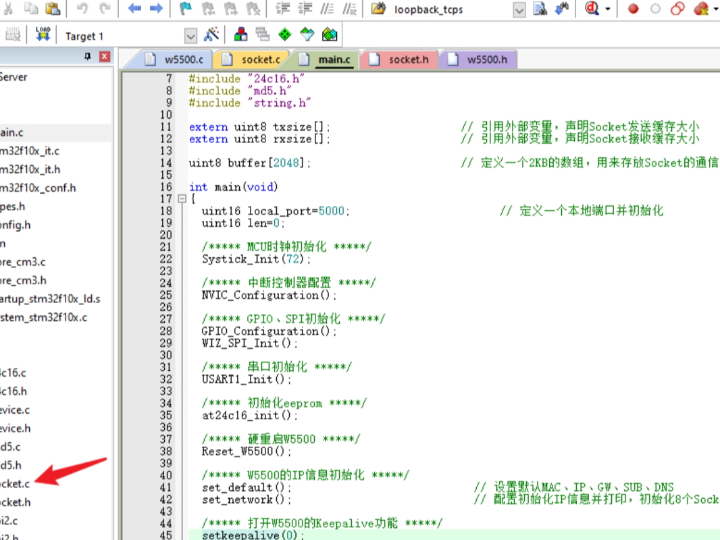
The article is a practical porting note rather than a full product write-up. Its stated goal is to configure the W5500 as a server for communication testing without DHCP, using an AG32VF407 development target, VS Code, and a transplanted TCP Server example. The workflow is straightforward: find a reference example, copy the core W5500 files, add a custom SPI/GPIO layer, adapt data types and naming conflicts, and then replace the example loop with a board-specific task loop.
From a network-stack perspective, this is a classic hardwired-TCP/IP split. The MCU does not implement a full software TCP/IP stack. Instead, the W5500 supplies the TCP server socket behavior, and the firmware mainly handles board initialization, SPI byte movement, reset timing, and application control flow. For education, that is useful because it exposes the boundary between transport offload and MCU-side logic without hiding everything behind a heavy middleware layer.
Architecturally, the visible pieces are small but clear: socket.c/.h and w5500.c/.h are imported from the example, a custom w5500_gpio layer is added for hardware access, and the main runtime loop is modified to fit the AG32 platform. That makes the article more about firmware integration than about protocol theory, but it still shows the minimum structure needed to move from a generic example to a board-specific TCP server.
Where WIZnet Fits
The exact WIZnet product here is the W5500. Its role is the embedded Ethernet controller and hardwired TCP/IP engine sitting between the AG32VF407 and the network. WIZnet’s documentation describes the W5500 as a single-chip controller with an embedded TCP/IP stack, integrated 10/100 Ethernet MAC and PHY, 32 KB internal packet buffer memory, support for eight independent hardware sockets, and an SPI interface that can run up to 80 MHz. Those features are why a small MCU can act as a TCP server without carrying the full protocol burden in firmware.
In this project, the W5500 is not a generic PHY companion. It owns the socket endpoint. The AG32VF407 only has to provide reset control, chip-level integration, and data movement over SPI. That is a good educational fit because students can see the firmware flow clearly: initialize pins, reset the chip, exchange bytes over SPI, call into the socket layer, and then run the server loop.
Implementation Notes
This project does use WIZnet products, and the article includes real code snippets, but it does not expose a public repository with line-addressable source files. I am therefore quoting only what is visible in the article.
Snippet 1 — custom SPI/GPIO board layer (w5500_gpio)
The article shows the added board-support initialization:
void W5500_spio_Init(void){SYS_EnableAPBClock(W5500_GPIO_MASK);GPIO_SetInput(W5500_GPIO, W5500_Input_GPIO_BITS);GPIO_SetOutput(W5500_GPIO, W5500_Output_GPIO_BITS);GPIO_SetHigh(W5500_GPIO, W5500_Output_GPIO_BITS);}
Why it matters: this is the platform boundary. It shows that the port is not abstract; the author had to define concrete GPIO ownership and default signal states before the W5500 driver could run on AG32VF407.
Snippet 2 — byte-level SPI transfer and reset path (w5500_gpio)
The article also shows a software-driven byte transfer and reset routine:
uint8_t W5500_ReadWriteByte(uint8_t bety){ ... W5500_SCK_L(); ... bety & 0x80 ? W5500_OUT_H() : W5500_OUT_L(); ... if (W5500_IN()) { data |= (1 << (7 - i)); } ... }
void W5500_Reset(void){W5500_RST_L();delay_us(2);W5500_RST_H();delay_us(1500e3);}
Why it matters: this code reveals the real firmware flow of the port. The transport stack may be offloaded into the W5500, but the MCU still owns the physical transaction timing and reset sequence. That is the essential lesson in this article: porting W5500 is mostly about getting the hardware access layer right, then letting the socket example sit on top.
The article also states that the imported files are socket.c/.h and w5500.c/.h, that unnecessary headers were removed, that a naming conflict around IR may require renaming it to W5500_IR, and that the example main loop was modified into the target board’s loop task. Those details matter because they show the practical friction points in W5500 bring-up: board I/O, type compatibility, symbol conflicts, and runtime integration.
Practical Tips / Pitfalls
Keep the porting boundary clean. Import the W5500 driver and socket layer as-is where possible, and isolate AG32-specific code inside a board layer such as w5500_gpio.
Watch for symbol collisions. The article explicitly warns that IR may already exist in the target SDK and may need to be renamed to W5500_IR.
Validate reset behavior early. If reset timing is wrong, socket code will fail in ways that look like network bugs rather than bring-up faults. The article includes an explicit reset routine; WIZnet also documents chip-level reset and initialization requirements.
Do not overcomplicate the first test. This article intentionally skips DHCP and uses the W5500 as a fixed TCP server for communication testing, which is the right first milestone.
Performance on this kind of port is usually limited less by the W5500 than by the MCU-side SPI path and loop design. A software-bit-banged SPI path is fine for education and bring-up, but hardware SPI will usually scale better once the server is stable. This is an inference from the article’s shown transfer routine and W5500’s SPI capabilities.
Keep the server example simple before adding higher-level protocols. WIZnet’s own application materials separate TCP function examples from more advanced services for the same reason.
FAQ
Why use the W5500 here instead of implementing the stack in software on AG32VF407?
Because the article’s goal is a quick, practical TCP server bring-up. The W5500 already provides hardwired TCP/IP handling and socket-level operation, so the firmware effort shifts from full network-stack development to driver porting and server control flow. That is a much better educational path for learning embedded Ethernet integration.
How does the W5500 connect to the platform in this project?
Through a custom GPIO/SPI board layer. The article shows GPIO initialization, software-controlled SPI byte transfers, and a dedicated reset routine, which together form the hardware interface between AG32VF407 and the W5500.
What role does the W5500 play in this specific project?
It acts as the TCP server endpoint. The imported socket and w5500 files provide the server-side Ethernet functionality, while the AG32 firmware adapts them to the local board and loop structure.
Can beginners follow this project?
Yes, if they already understand basic GPIO, SPI, and build integration. The article is suitable for education because it focuses on concrete porting steps rather than abstract networking theory, but a complete beginner may still need help understanding reset timing, pin control, and symbol adaptation.
How does this compare with LwIP on the MCU?
LwIP gives more software control, but it also places much more stack integration, RAM management, and debugging burden on the MCU firmware. The W5500 approach shown here keeps the architecture simpler: the MCU ports the hardware interface and runs the application loop, while the W5500 handles TCP/IP and socket behavior.
Source
Original link: CSDN article “调试W5500(作为服务器).” The page states CC 4.0 BY-SA.
Additional product facts were verified against WIZnet’s official W5500 documentation and TCP application notes.
Tags
W5500, WIZnet, AG32VF407, TCP Server, Embedded Ethernet, SPI, Firmware Porting, Socket Offload, Education, Hardwired TCP/IP, Board Bring-up, MCU Networking