



How to Connect MQTT with W5500 on STM32F103?
This maker project combines an STM32F103 microcontroller, a WIZnet W5500 Ethernet controller, a DHT11 temperature and humidity sensor, and an MQTT client.
How to Connect MQTT with W5500 on STM32F103?
Summary
This maker project combines an STM32F103 microcontroller, a WIZnet W5500 Ethernet controller, a DHT11 temperature and humidity sensor, and an MQTT client. The STM32 reads environmental data, opens a TCP connection through a W5500 hardware socket, publishes sensor values to an MQTT broker, receives subscribed control messages, and switches an onboard LED in response. The W5500 provides the wired Ethernet and TCP transport beneath the MQTT session.
What the Project Does
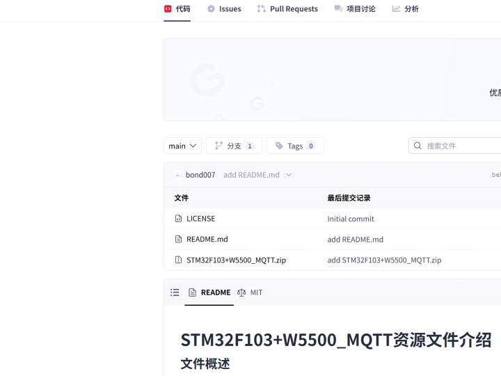
The repository presents an STM32F103 and W5500 remote-control example built around MQTT. According to the project overview, the firmware reads temperature and humidity from a DHT11 sensor, uploads those values through Ethernet, receives MQTT commands, and controls an LED from a mobile application. The repository is marked with an MIT license.
The expected application data flow is:
DHT11 sensor → STM32F103 → MQTT payload → W5500 TCP socket → Ethernet → MQTT broker → mobile application
The command path operates in the opposite direction:
Mobile application → MQTT broker → subscribed MQTT message → W5500 TCP socket → STM32F103 → LED control
MQTT does not replace TCP. The MQTT client first establishes a TCP connection to the broker, sends an MQTT CONNECT packet, waits for CONNACK, subscribes to one or more topics, and then exchanges PUBLISH, keepalive, and acknowledgment packets over the same connection.
The public repository overview confirms the project purpose and main hardware, but it does not expose enough source detail in the reviewed interface to verify exact broker addresses, topic names, MQTT quality-of-service settings, function names, file paths, or reconnection code. Those details should be checked in the downloaded project before reuse.
Where WIZnet Fits
The WIZnet product is the W5500, connected to the STM32F103 through SPI. The W5500 integrates a hardwired TCP/IP stack, 10/100 Ethernet MAC and PHY, eight hardware sockets, and 32 KB of internal packet memory.
In this project, the W5500 provides the TCP transport used by MQTT. It does not interpret MQTT topics or application payloads. The responsibilities are divided as follows:
STM32F103 application
- Reads the DHT11 sensor
- Formats MQTT payload data
- Selects publish and subscribe topics
- Parses received commands
- Controls the LED
- Manages MQTT keepalive and reconnection policy
MQTT client layer
- Creates
CONNECT,SUBSCRIBE,PUBLISH,PINGREQ, and disconnect packets - Parses broker responses
- Tracks MQTT packet identifiers and session state
W5500 socket layer
- Opens and closes the TCP socket
- Connects to the broker IP address and port
- Sends encoded MQTT packets
- Receives broker data
- Reports socket state and timeout conditions
W5500 hardware
- Handles supported TCP/IP processing
- Maintains socket state
- Stores network data in internal TX and RX buffers
- Provides Ethernet MAC and PHY operation
WIZnet’s ioLibrary includes Berkeley-style socket APIs, W5500 drivers, and an MQTT client application module. Its published directory structure contains W5500 device files under Ethernet/W5500 and MQTT components such as mqtt_interface.c, MQTTClient.c, and their headers under Internet/MQTT.
For a maker project on an STM32F103, this architecture avoids placing the full TCP/IP stack and Ethernet packet buffering in MCU RAM. The MCU still runs the MQTT application logic, but the W5500 handles the supported network and transport operations.
Implementation Notes
The repository overview does not provide verifiable source files or line-level code, so no project code is reproduced here. The following describes the MQTT and W5500 integration sequence that should be verified against the downloaded firmware.
W5500 Initialization
The firmware should initialize the network interface before starting MQTT:
- Configure STM32 GPIO and SPI.
- Reset the W5500.
- Register SPI read, write, and chip-select callbacks.
- Allocate W5500 TX and RX memory across the required sockets.
- Configure MAC address, IPv4 address, subnet mask, and gateway.
- Confirm that the Ethernet PHY reports a valid link.
- Resolve the broker hostname or use a configured broker IP address.
Only one socket is normally required for a basic MQTT session. Additional sockets may be needed for DHCP, DNS, diagnostics, or other network services.
TCP Connection to the Broker
MQTT communication begins by opening a W5500 TCP socket:
- Select an unused W5500 socket.
- Configure it for TCP mode.
- Open the socket.
- Connect to the MQTT broker’s IP address and TCP port.
- Wait until the socket reaches the established state.
- Apply a connection timeout so the firmware cannot wait indefinitely.
The broker port is an application configuration value. The reviewed repository overview does not reveal whether the example uses an unencrypted MQTT port, a private broker, or a cloud service.
MQTT Session Establishment
Once TCP is established, the firmware sends an MQTT CONNECT packet containing settings such as:
- Client identifier
- Keepalive interval
- Clean-session or persistent-session preference
- Optional username and password
- Optional last-will configuration
The client must then wait for a valid CONNACK. A successful TCP connection alone does not mean that the broker has accepted the MQTT session.
After CONNACK, the client sends a SUBSCRIBE request for the LED-control topic. It should wait for SUBACK before assuming that remote commands will be delivered.
DHT11 Publishing Flow
A practical publishing loop is:
- Read temperature and humidity from the DHT11.
- Check the sensor result for timeout or checksum failure.
- Format the values as a compact payload.
- Encode an MQTT
PUBLISHpacket. - Check that the W5500 socket remains connected.
- Send the complete MQTT packet through the TCP socket.
- Record the next publication time.
The payload can be plain text or structured data such as JSON. On an STM32F103, a compact representation reduces formatting code, packet size, and temporary buffer use.
Publishing should use a fixed interval rather than transmitting continuously. The interval should be long enough to avoid unnecessary broker traffic and short enough for the intended monitoring behavior.
Subscribed LED-Control Flow
The receive loop should regularly check the W5500 socket for incoming data. When bytes are available, the MQTT parser must handle them as a TCP stream.
A reliable sequence is:
- Read available TCP data from the W5500 RX buffer.
- Append it to an MQTT receive buffer.
- Parse the MQTT fixed header and remaining-length field.
- Wait for more data if the packet is incomplete.
- Extract the topic and payload from a complete
PUBLISH. - Compare the topic with the configured LED-control topic.
- Validate the command payload.
- Set or clear the LED GPIO.
- Send any required MQTT acknowledgment.
The firmware must not assume that one W5500 receive operation contains exactly one complete MQTT packet. TCP can split one MQTT packet across several reads or combine several packets into one read.
Keepalive and Reconnection
MQTT keepalive is required when the connection is otherwise idle. The firmware should track the time since the last network exchange and send PINGREQ before the keepalive interval expires. It should confirm receipt of PINGRESP.
The recovery logic should detect:
- Ethernet cable removal
- PHY link loss
- Broker restart
- TCP socket closure
- Missing
CONNACK - Missing
PINGRESP - Failed publication
- Invalid MQTT packet
- DHCP lease loss, when DHCP is used
A sensible recovery order is:
- Reopen the failed TCP socket.
- Reconnect to the broker.
- Send MQTT
CONNECTagain. - Resubscribe to control topics.
- Reinitialize the W5500 only when socket-level recovery fails.
- Reset the entire MCU only as the final recovery action.
W5500 Socket Integration
WIZnet ioLibrary provides Berkeley-style socket operations over W5500 hardware sockets. The application can use socket-like calls for open, connect, send, receive, disconnect, and close while the chip-specific driver performs register and buffer access through SPI. The official ioLibrary also includes an MQTT client module derived from Paho MQTT 3.1.1.
The integration boundary should remain clear:
- The MQTT client creates and parses MQTT packets.
- The socket layer moves a TCP byte stream.
- The W5500 driver accesses chip registers and buffers.
- The STM32 port supplies SPI, chip-select, reset, timing, and optional critical-section functions.
W5500 Compared with LwIP
LwIP is a software TCP/IP stack designed for embedded systems with limited memory. It supports IPv4, IPv6, TCP, UDP, DHCP, DNS, optional Berkeley-style sockets, and an MQTT client, among other features. Its documentation notes that it is intended for systems with tens of kilobytes of available RAM and roughly 40 KB of code ROM, although actual requirements vary with configuration.
The architectural difference is where TCP/IP processing occurs.
W5500 design
- TCP/IP processing runs in dedicated W5500 hardware.
- Packet memory is provided inside the W5500.
- The STM32 uses SPI and hardware socket registers.
- The network interface is limited to the protocols and socket model supported by the chip.
- Eight hardware sockets are available.
LwIP design
- TCP/IP processing runs as MCU software.
- Packet buffers use MCU RAM or externally connected memory.
- The network driver interfaces with an Ethernet MAC or another network device.
- The developer has broader control over stack configuration and protocols.
- CPU, RAM, and flash usage depend on enabled features and API choice.
For this maker project, W5500 reduces the amount of network-stack integration required on the STM32F103 and leaves more MCU resources for sensor handling and MQTT application logic. LwIP is more appropriate when the selected STM32 already includes an Ethernet MAC, when software-level protocol flexibility is important, or when the application needs features beyond the W5500 hardware socket model.
Practical Tips / Pitfalls
- Confirm the W5500 PHY link before attempting MQTT. Repeated broker failures may actually be cable, magnetics, switch, or link-negotiation problems.
- Keep the MQTT receive parser independent of individual socket reads. TCP does not preserve MQTT packet boundaries.
- Allocate separate buffers for MQTT encoding and W5500 transfer carefully; large fixed buffers can consume a significant part of STM32F103 RAM.
- Use unique MQTT client identifiers. Brokers may disconnect an existing session when another client connects with the same identifier.
- Validate DHT11 reads before publishing. Sensor timeouts or checksum failures should not be uploaded as legitimate measurements.
- Add bounded reconnect delays. Immediate continuous reconnect attempts can overload the broker and make local debugging difficult.
- Treat broker authentication as separate from transport security. The W5500 supplies TCP offload, but TLS requires additional host-side or external security support.
FAQ
Q: Why use the W5500 for this MQTT maker project?
The W5500 provides hardware TCP/IP sockets, internal packet memory, and an integrated Ethernet MAC and PHY. This allows the STM32F103 to focus on DHT11 sampling, MQTT packet handling, and LED control instead of running the complete TCP/IP stack in software.
Q: How does the W5500 connect to the STM32F103?
It uses SPI with SCLK, MOSI, MISO, and chip select. A practical design also connects reset and optionally the W5500 interrupt output. The exact GPIO assignment used by this repository could not be verified from the public overview and should be checked in the downloaded source.
Q: What role does the W5500 play in the MQTT connection?
The W5500 opens and maintains the TCP connection to the broker and transfers MQTT packet bytes between the broker and STM32. It does not understand topics, DHT11 values, or LED commands; those are handled by the MQTT and application layers.
Q: Can beginners follow this project?
A maker familiar with STM32 GPIO, SPI, IPv4 addressing, and basic C programming can follow the architecture. MQTT adds several state-management requirements, including broker connection, subscription, packet parsing, keepalive, and reconnection, so testing each layer separately is recommended.
Q: How does W5500 compare with LwIP for this project?
W5500 performs supported TCP/IP processing and buffering in hardware, while LwIP implements the network stack in MCU software. W5500 usually reduces STM32 RAM and integration demands, whereas LwIP offers more protocol flexibility and works naturally with MCUs that already include an Ethernet MAC.
Source
Original project: Universal-Tool, STM32F103 and W5500 MQTT resource project on GitCode. The overview describes DHT11 publishing, MQTT remote control, LED operation, and an MIT license.
WIZnet technical references: W5500 official documentation and WIZnet ioLibrary Driver, including the W5500 device layer, Berkeley-style socket API, and MQTT client module.
Comparison reference: Official lwIP project documentation describing its software TCP/IP architecture, embedded memory goals, supported protocols, socket interfaces, and MQTT client.
License: The GitCode repository is marked MIT. Individual third-party MQTT, sensor, or driver files may contain separate notices and should be reviewed before redistribution.
Tags
#W5500 #WIZnet #STM32F103 #MQTT #DHT11 #Ethernet #MakerProject #ioLibrary #TCPIPOffload #LwIP #RemoteControl #EmbeddedIoT
STM32F103에서 W5500으로 MQTT에 어떻게 연결할 수 있을까?
요약
이 메이커 프로젝트는 STM32F103 마이크로컨트롤러, WIZnet W5500 이더넷 컨트롤러, DHT11 온습도 센서, MQTT 클라이언트를 결합합니다. STM32는 환경 데이터를 읽고, W5500 하드웨어 소켓을 통해 TCP 연결을 연 뒤, 센서 값을 MQTT 브로커에 게시합니다. 또한 구독한 제어 메시지를 수신하여 모바일 애플리케이션의 명령에 따라 보드의 LED를 제어합니다. W5500은 MQTT 세션 아래에서 유선 이더넷과 TCP 전송 계층을 담당합니다.
프로젝트가 하는 일
이 저장소는 STM32F103과 W5500을 이용한 MQTT 원격 제어 예제를 소개합니다. 프로젝트 개요에 따르면 펌웨어는 DHT11 센서에서 온도와 습도를 읽고, 이 값을 이더넷으로 업로드하며, MQTT 명령을 수신해 모바일 애플리케이션에서 LED를 제어합니다. 저장소에는 MIT 라이선스가 표시되어 있습니다.
예상되는 애플리케이션 데이터 흐름은 다음과 같습니다.
DHT11 센서 → STM32F103 → MQTT 페이로드 → W5500 TCP 소켓 → 이더넷 → MQTT 브로커 → 모바일 애플리케이션
명령 경로는 반대 방향으로 동작합니다.
모바일 애플리케이션 → MQTT 브로커 → 구독된 MQTT 메시지 → W5500 TCP 소켓 → STM32F103 → LED 제어
MQTT는 TCP를 대체하지 않습니다. MQTT 클라이언트는 먼저 브로커와 TCP 연결을 생성하고, MQTT CONNECT 패킷을 전송한 뒤 CONNACK을 기다립니다. 이후 하나 이상의 토픽을 구독하고, 동일한 연결을 통해 PUBLISH, keepalive, 확인 응답 패킷을 교환합니다.
공개된 저장소 개요에서는 프로젝트 목적과 주요 하드웨어는 확인할 수 있지만, 검토한 화면만으로는 정확한 브로커 주소, 토픽 이름, MQTT QoS 설정, 함수 이름, 파일 경로, 재연결 코드를 검증하기 어렵습니다. 실제 재사용 전에는 다운로드한 프로젝트에서 이러한 세부사항을 확인해야 합니다.
WIZnet이 적용되는 위치
사용되는 WIZnet 제품은 W5500이며, STM32F103과 SPI로 연결됩니다. W5500은 하드와이어드 TCP/IP 스택, 10/100 이더넷 MAC과 PHY, 8개의 하드웨어 소켓, 32 KB 내부 패킷 메모리를 통합합니다.
이 프로젝트에서 W5500은 MQTT가 사용하는 TCP 전송을 제공합니다. W5500이 MQTT 토픽이나 애플리케이션 페이로드를 해석하는 것은 아닙니다. 역할은 다음과 같이 나뉩니다.
STM32F103 애플리케이션
DHT11 센서 읽기
MQTT 페이로드 포맷 구성
발행 및 구독 토픽 선택
수신 명령 해석
LED 제어
MQTT keepalive 및 재연결 정책 관리
MQTT 클라이언트 계층
CONNECT, SUBSCRIBE, PUBLISH, PINGREQ, 연결 종료 패킷 생성
브로커 응답 해석
MQTT 패킷 식별자와 세션 상태 관리
W5500 소켓 계층
TCP 소켓 열기 및 닫기
브로커 IP 주소와 포트로 연결
인코딩된 MQTT 패킷 전송
브로커 데이터 수신
소켓 상태 및 타임아웃 보고
W5500 하드웨어
지원되는 TCP/IP 처리
소켓 상태 유지
내부 TX/RX 버퍼에 네트워크 데이터 저장
이더넷 MAC 및 PHY 동작 제공
WIZnet ioLibrary는 Berkeley 스타일의 소켓 API, W5500 드라이버, MQTT 클라이언트 애플리케이션 모듈을 포함합니다. 공개된 디렉터리 구조에는 Ethernet/W5500 아래의 W5500 장치 파일과 Internet/MQTT 아래의 mqtt_interface.c, MQTTClient.c 및 관련 헤더가 포함됩니다.
STM32F103 기반 메이커 프로젝트에서는 이 구조를 사용해 전체 TCP/IP 스택과 이더넷 패킷 버퍼를 MCU RAM에 배치하는 부담을 줄일 수 있습니다. MCU는 MQTT 애플리케이션 로직을 계속 실행하지만, 지원되는 네트워크 및 전송 처리는 W5500이 담당합니다.
구현 참고 사항
저장소 개요만으로는 소스 파일이나 코드 라인을 검증할 수 없으므로 실제 프로젝트 코드는 재사용하지 않습니다. 아래 내용은 다운로드한 펌웨어에서 확인해야 할 MQTT 및 W5500 통합 순서를 설명합니다.
W5500 초기화
MQTT를 시작하기 전에 네트워크 인터페이스를 초기화해야 합니다.
STM32 GPIO와 SPI를 설정합니다.
W5500을 리셋합니다.
SPI 읽기, 쓰기, 칩 선택 콜백을 등록합니다.
필요한 소켓에 W5500 TX/RX 메모리를 할당합니다.
MAC 주소, IPv4 주소, 서브넷 마스크, 게이트웨이를 설정합니다.
이더넷 PHY 링크가 정상인지 확인합니다.
브로커 호스트명을 해석하거나 설정된 브로커 IP를 사용합니다.
기본 MQTT 세션에는 일반적으로 소켓 1개가 필요합니다. DHCP, DNS, 진단, 기타 네트워크 서비스에는 추가 소켓이 필요할 수 있습니다.
브로커와 TCP 연결
MQTT 통신은 W5500 TCP 소켓을 여는 것으로 시작합니다.
사용하지 않는 W5500 소켓을 선택합니다.
TCP 모드로 설정합니다.
소켓을 엽니다.
MQTT 브로커의 IP 주소와 TCP 포트로 연결합니다.
소켓 상태가 연결 완료 상태가 될 때까지 기다립니다.
무한 대기를 방지하기 위해 연결 타임아웃을 적용합니다.
브로커 포트는 애플리케이션 설정값입니다. 검토한 저장소 개요에서는 비암호화 MQTT 포트, 사설 브로커, 클라우드 서비스 중 어느 것을 사용하는지 확인할 수 없습니다.
MQTT 세션 수립
TCP 연결이 완료되면 펌웨어는 다음 정보를 포함한 MQTT CONNECT 패킷을 전송합니다.
클라이언트 식별자
keepalive 간격
clean session 또는 persistent session 설정
선택적 사용자 이름과 비밀번호
선택적 last will 설정
클라이언트는 유효한 CONNACK을 기다려야 합니다. TCP 연결 성공만으로는 브로커가 MQTT 세션을 승인했다는 의미가 아닙니다.
CONNACK 수신 후 LED 제어 토픽에 대한 SUBSCRIBE 요청을 전송합니다. 원격 명령을 받을 수 있다고 판단하기 전에 SUBACK을 확인해야 합니다.
DHT11 데이터 발행 흐름
실용적인 발행 루프는 다음과 같습니다.
DHT11에서 온도와 습도를 읽습니다.
센서 타임아웃이나 체크섬 오류를 확인합니다.
값을 간결한 페이로드로 변환합니다.
MQTT PUBLISH 패킷을 인코딩합니다.
W5500 소켓이 여전히 연결 상태인지 확인합니다.
완성된 MQTT 패킷을 TCP 소켓으로 전송합니다.
다음 발행 시간을 기록합니다.
페이로드는 일반 텍스트나 JSON과 같은 구조화된 데이터가 될 수 있습니다. STM32F103에서는 간결한 표현을 사용하면 포맷 코드, 패킷 크기, 임시 버퍼 사용량을 줄일 수 있습니다.
데이터는 계속해서 전송하기보다 고정된 주기로 발행하는 것이 좋습니다. 발행 주기는 불필요한 브로커 트래픽을 줄이면서도 원하는 모니터링 주기를 만족하도록 설정해야 합니다.
구독된 LED 제어 흐름
수신 루프는 W5500 소켓에 들어온 데이터를 주기적으로 확인해야 합니다. 데이터가 있으면 MQTT 파서는 이를 TCP 스트림으로 처리해야 합니다.
신뢰성 있는 수신 순서는 다음과 같습니다.
W5500 RX 버퍼에서 사용 가능한 TCP 데이터를 읽습니다.
MQTT 수신 버퍼에 데이터를 추가합니다.
MQTT 고정 헤더와 remaining length 필드를 해석합니다.
패킷이 완전하지 않으면 추가 데이터를 기다립니다.
완성된 PUBLISH에서 토픽과 페이로드를 추출합니다.
토픽을 설정된 LED 제어 토픽과 비교합니다.
명령 페이로드를 검증합니다.
LED GPIO를 설정하거나 해제합니다.
필요한 MQTT 확인 응답을 전송합니다.
펌웨어는 한 번의 W5500 수신 작업에 하나의 완전한 MQTT 패킷이 들어온다고 가정해서는 안 됩니다. TCP는 하나의 MQTT 패킷을 여러 번에 나누어 전달하거나, 여러 패킷을 한 번의 읽기에 결합할 수 있습니다.
Keepalive 및 재연결
연결이 유휴 상태일 때는 MQTT keepalive가 필요합니다. 펌웨어는 마지막 네트워크 교환 이후 경과 시간을 추적하고, keepalive 간격이 끝나기 전에 PINGREQ를 전송해야 합니다. 또한 PINGRESP 수신을 확인해야 합니다.
복구 로직은 다음 상황을 감지해야 합니다.
이더넷 케이블 분리
PHY 링크 손실
브로커 재시작
TCP 소켓 종료
CONNACK 미수신
PINGRESP 미수신
발행 실패
잘못된 MQTT 패킷
DHCP 사용 시 임대 주소 손실
적절한 복구 순서는 다음과 같습니다.
실패한 TCP 소켓을 다시 엽니다.
브로커에 다시 연결합니다.
MQTT CONNECT를 다시 전송합니다.
제어 토픽을 다시 구독합니다.
소켓 수준 복구에 실패할 때만 W5500을 재초기화합니다.
전체 MCU 리셋은 마지막 수단으로 사용합니다.
W5500 소켓 통합
WIZnet ioLibrary는 W5500 하드웨어 소켓 위에서 Berkeley 스타일 소켓 동작을 제공합니다. 애플리케이션은 소켓 열기, 연결, 전송, 수신, 연결 종료, 닫기 함수를 사용할 수 있고, 칩별 드라이버는 SPI를 통해 레지스터와 버퍼에 접근합니다. 공식 ioLibrary에는 Paho MQTT 3.1.1 기반의 MQTT 클라이언트 모듈도 포함됩니다.
통합 계층의 경계를 명확히 유지해야 합니다.
MQTT 클라이언트는 MQTT 패킷을 생성하고 해석합니다.
소켓 계층은 TCP 바이트 스트림을 전송합니다.
W5500 드라이버는 칩 레지스터와 버퍼에 접근합니다.
STM32 포팅 계층은 SPI, 칩 선택, 리셋, 타이밍, 선택적 임계 구역 기능을 제공합니다.
W5500과 LwIP 비교
LwIP는 메모리가 제한된 임베디드 시스템을 위한 소프트웨어 TCP/IP 스택입니다. IPv4, IPv6, TCP, UDP, DHCP, DNS, 선택적 Berkeley 스타일 소켓, MQTT 클라이언트 등을 지원합니다. 실제 요구량은 설정에 따라 달라지지만, 수십 KB 수준의 RAM과 약 40 KB 수준의 코드 ROM을 목표로 설계된 것으로 알려져 있습니다.
아키텍처 차이는 TCP/IP 처리가 어디에서 실행되는지에 있습니다.
W5500 설계
TCP/IP 처리가 전용 W5500 하드웨어에서 실행됩니다.
패킷 메모리는 W5500 내부에 있습니다.
STM32는 SPI와 하드웨어 소켓 레지스터를 사용합니다.
네트워크 기능은 칩이 지원하는 프로토콜과 소켓 구조로 제한됩니다.
최대 8개의 하드웨어 소켓을 사용할 수 있습니다.
LwIP 설계
TCP/IP 처리가 MCU 소프트웨어에서 실행됩니다.
패킷 버퍼는 MCU RAM이나 외부 메모리를 사용합니다.
네트워크 드라이버는 이더넷 MAC 또는 다른 네트워크 장치와 연결됩니다.
개발자가 스택 설정과 프로토콜을 더 넓게 제어할 수 있습니다.
CPU, RAM, 플래시 사용량은 활성화된 기능과 API에 따라 달라집니다.
이 메이커 프로젝트에서는 W5500이 STM32F103에서 요구되는 네트워크 스택 통합 작업을 줄이고, 센서 처리와 MQTT 애플리케이션 로직에 더 많은 MCU 자원을 남겨줄 수 있습니다.
반면 선택한 STM32에 이미 이더넷 MAC이 포함되어 있거나, 소프트웨어 수준에서 더 높은 프로토콜 유연성이 필요하거나, W5500 하드웨어 소켓 모델을 넘어서는 기능이 필요하다면 LwIP가 더 적합할 수 있습니다.
실무 팁과 주의사항
MQTT를 시도하기 전에 W5500 PHY 링크를 확인해야 합니다. 반복되는 브로커 연결 실패가 실제로는 케이블, 마그네틱스, 스위치, 링크 협상 문제일 수 있습니다.
MQTT 수신 파서를 개별 소켓 읽기 동작과 분리해야 합니다. TCP는 MQTT 패킷 경계를 보존하지 않습니다.
MQTT 인코딩 버퍼와 W5500 전송 버퍼를 신중하게 설계해야 합니다. 큰 고정 버퍼는 STM32F103 RAM을 많이 사용할 수 있습니다.
고유한 MQTT 클라이언트 식별자를 사용해야 합니다. 동일한 식별자로 다른 클라이언트가 접속하면 브로커가 기존 세션을 종료할 수 있습니다.
발행 전 DHT11 읽기 결과를 검증해야 합니다. 센서 타임아웃이나 체크섬 오류를 정상 측정값으로 업로드해서는 안 됩니다.
재연결 지연과 재시도 횟수에 제한을 두어야 합니다. 즉시 반복되는 연결 시도는 브로커에 부하를 주고 로컬 디버깅도 어렵게 만듭니다.
브로커 인증과 전송 보안을 구분해야 합니다. W5500은 TCP 오프로드를 제공하지만, TLS는 호스트 측 또는 외부 보안 장치에서 별도로 처리해야 합니다.
FAQ
Q: 이 MQTT 메이커 프로젝트에서 W5500을 사용하는 이유는 무엇인가요?
W5500은 하드웨어 TCP/IP 소켓, 내부 패킷 메모리, 통합 이더넷 MAC과 PHY를 제공합니다. 따라서 STM32F103은 전체 TCP/IP 스택을 소프트웨어로 실행하는 대신 DHT11 측정, MQTT 패킷 처리, LED 제어에 집중할 수 있습니다.
Q: W5500은 STM32F103과 어떻게 연결하나요?
SCLK, MOSI, MISO, 칩 선택 신호를 사용하는 SPI로 연결합니다. 실용적인 설계에서는 리셋 핀과 필요에 따라 W5500 인터럽트 출력도 연결합니다. 이 저장소의 정확한 GPIO 배치는 공개 개요에서 확인할 수 없으므로 다운로드한 소스에서 확인해야 합니다.
Q: MQTT 연결에서 W5500은 어떤 역할을 하나요?
W5500은 브로커와의 TCP 연결을 열고 유지하며, MQTT 패킷 바이트를 브로커와 STM32 사이에서 전달합니다. 토픽, DHT11 값, LED 명령은 해석하지 않으며, 이러한 기능은 MQTT 및 애플리케이션 계층에서 처리합니다.
Q: 초보자도 이 프로젝트를 따라 할 수 있나요?
STM32 GPIO, SPI, IPv4 주소 설정, 기본 C 프로그래밍에 익숙한 메이커라면 구조를 따라갈 수 있습니다. 다만 MQTT에는 브로커 연결, 구독, 패킷 파싱, keepalive, 재연결과 같은 상태 관리가 필요하므로 각 계층을 별도로 시험하는 것이 좋습니다.
Q: 이 프로젝트에서 W5500과 LwIP는 어떻게 다른가요?
W5500은 지원되는 TCP/IP 처리와 버퍼링을 하드웨어에서 수행하고, LwIP는 네트워크 스택을 MCU 소프트웨어에서 실행합니다. W5500은 일반적으로 STM32의 RAM과 통합 부담을 줄이고, LwIP는 더 높은 프로토콜 유연성을 제공하며 이더넷 MAC이 내장된 MCU와 자연스럽게 결합됩니다.
출처
원본 프로젝트: GitCode의 Universal-Tool STM32F103 및 W5500 MQTT 프로젝트
https://gitcode.com/Universal-Tool/69845
프로젝트 개요에서는 DHT11 데이터 발행, MQTT 원격 제어, LED 동작, MIT 라이선스를 설명합니다.
WIZnet 기술 참고 자료: W5500 공식 문서 및 WIZnet ioLibrary Driver
https://docs.wiznet.io/Product/Chip/Ethernet/W5500/datasheet
https://github.com/Wiznet/ioLibrary_Driver
W5500 장치 계층, Berkeley 스타일 소켓 API, MQTT 클라이언트 모듈 관련 자료를 제공합니다.
비교 참고 자료: 공식 LwIP 프로젝트 문서
https://github.com/lwip-tcpip/lwip
소프트웨어 TCP/IP 구조, 임베디드 메모리 목표, 지원 프로토콜, 소켓 인터페이스, MQTT 클라이언트 관련 내용을 제공합니다.
라이선스: GitCode 저장소에는 MIT 라이선스가 표시되어 있습니다. 개별 MQTT, 센서, 드라이버 파일에는 별도의 라이선스 고지가 포함될 수 있으므로 재배포 전에 각 파일을 확인해야 합니다.
태그
#W5500 #WIZnet #STM32F103 #MQTT #DHT11 #Ethernet #MakerProject #ioLibrary #TCPIPOffload #LwIP #RemoteControl #EmbeddedIoT