
Hi3516DV300 Chip Manual_Hi3518EV300
Hi3516DV300 Chip Manual_Hi3518EV300
Hello everyone, it's great to see you again. I'm your friend, QuanChanJun.
information
Current version author's contact information (valid indefinitely): E-mail: WindForest@yeah.net
Current version: 2022-4-16-R1.0-Pre-Release-Feedback Collection
5 Common peripheral device operations
This chapter introduces the usage methods of some common and frequently used peripherals. You can practice selectively as needed.
5.1 USB Wireless Network Adapter
This section uses the RTL8188EUS as an example to illustrate how to use the driver provided in the kernel to enable the kernel to recognize the device, and also provides an example of the process of using the network card to connect to a router .
[Prerequisites] This section will directly use the binary file obtained in section 4.1 wpa_supplicant .
[Note] This section uses the network card as a STA (Station) as an example. For an example of using it as an AP (Access Point), please refer to the relevant content in section 4.2 hostapd or consult relevant online resources.
5.1.1 Enabling Driver Support in the Kernel
Execute the command in the kernel directory menuconfigto enter the kernel configuration interface.
make ARCH=arm CROSS_COMPILE=arm-himix200-linux- menuconfigMake the following modifications:
- Networking support
- Select "RF switch subsystem support". Note: This option is used to avoid the "rfkill: Cannot open RFKILL control device" error in wpa_supplicant.
- Networking support -> Wireless
- Select the "cfg80211 – wireless configuration API " option to compile it into the kernel;
- Select the "cfg80211 wireless extensions compatibility" option;
- Select the "Generic IEEE 802.11 Networking Stack (mac80211)" option to compile it into the kernel.
- Device Drivers -> Network device support
- Select the "Wireless LAN" option, compile it into the kernel, and deselect all its sub-options.
- Device Drivers
- Select the "Staging drivers" item, and then select the sub-item "Realtek RTL8188EU Wireless LAN NIC driver" to compile it into the kernel.
Save and exit, then recompile the kernel image.
5.1.2 Prepare the firmware files required for the driver
The RTL8188EUS driver included in the kernel requires corresponding binary firmware when mounting the device. This firmware is compatible with the one provided in the Linux distribution on the development machine. Simply copy the /lib/firmware/rtlwifi/rtl8188eufw.bin file from the development machine to the same directory on the development board (create it if it doesn't exist).
5.1.3 Connecting to a hotspot using wpa_supplicant
Create a wpa_supplicant runtime configuration file named /etc/wpa.conf on the development board . An example configuration is shown below:
# 项目仅需要wpa_supplicant因此该控制接口可不引出,否则需为/var/run目录设置可写挂载
# ctrl_interface=/var/run/wpa_supplicant

# AP连接参数配置需根据实际进行修改,以下为示例
network={

    ssid="TP-LINK_EBA438"
    key_mgmt=WPA-PSK
    psk="12345678"
}
The following command can be used to invoke wpa_supplicant to connect to the network:
wpa_supplicant -D wext -i wlan0 -c /etc/wpa.conf &The network connection is successful when the terminal prints the following information:
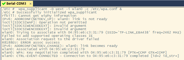
To obtain an IP address automatically, you need to run a DHCP client (the corresponding AP needs to be configured to run a DHCP server, which is enabled by default on the router
First, copy the example/simple.script file from the Busybox source code directory to the /usr/share/default.script file on the target development board and grant it executable permissions. Then, use the following command to start the Busybox built-in DHCP client:
udhcpc -i wlan0 -b5.1.4 Using hostapd to use the network card as an access point
For more detailed instructions and examples of using a USB wireless network adapter as an access point, please refer to the relevant content in section 4.2 hostapd or consult relevant online resources.
5.2 TF Card Mounting
In the previous chapters, after our development board boots into the Shell, its root directory is the partition where the root file system is located. In order to access the empty partition we reserved, we need to use mountthe command to mount it to an existing directory, and then accessing the mount point is to access the mounted device itself.
If you have already learned mountthe command, you can skip the manual mounting section in this chapter. Otherwise, I suggest you take the time to learn it, because mounting operations are extremely common in embedded development (at this moment, I am actually thinking of NFS, which you also need to learn).
[Differences in Automatic Mounting of USB Flash Drives] This section uses a TF card as an example because TF cards are more commonly used than USB flash drives in IPCs. Automatic mounting of USB flash drives is similar to that of TF cards, only the corresponding device node names are different. There are many examples online; you can try them out.
For example, the device node corresponding to the current USB drive is /dev/sda.
5.2.1 Manual Mounting
The kernel has MMC support enabled by default; you can see the recognition information by inserting the TF card into the development board.
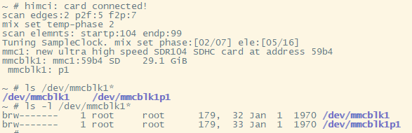
For a single-partition TF card, /dev/mmcblk1 is the block device node of the TF card, which contains the entire space of the TF card; /dev/mmcblk1p1 is also a block device, which refers to the unique partition on the TF card.
Use the following command to mount the card to the /mnt directory:
mount /dev/mmcblk1p1 /mntAccessing the /mnt mount point then accesses the TF card. The TF card file system used in the test was FAT32. If using a different file system, you may need to manually specify it using the -t parameter. Additionally, the file systems supported by the kernel can cat /proc/filesystemsbe viewed using the command.
After use, use umount /mnt/the command to unmount the mount point and then eject the TF card.
5.2.2 Using mdev to automatically mount devices
mdev is a lightweight device management program that uses the uevent_helper mechanism to obtain kernel uevent messages and is widely used in various embedded systems . mdev is integrated into Busybox and can be found under the Linux System Utilities entry in the build configuration interface. Busybox provides introductory documentation for it; see docs/mdev.txt .
According to the reference documentation, the following support requirements must be met to use the runtime custom dynamic mount feature:
- sysfs needs to be enabled and installed.
- Kernel hotplug needs to be enabled.
- It is necessary to instruct the kernel to call mdev when adding or removing devices.
- If the proc filesystem is already enabled, use [configuration method]
echo /sbin/mdev > /proc/sys/kernel/hotplugto set it. - If the proc filesystem is not enabled, use [configuration method]
sysctl -w kernel.hotplug=/sbin/mdevto set it.
- If the proc filesystem is already enabled, use [configuration method]
- Ensure that /dev is a tmpfs filesystem, or ensure that there is enough space on the storage.
- Create the /dev/pts directory and mount it as a devpts filesystem.
- Write the /etc/mdev.conf configuration file
Fortunately, if you are using the root file system template provided by Hisilicon, then the above conditions are met by default. The core issue of using mdev to implement dynamic mounting becomes the manipulation of the configuration file. A configuration file template can be found in examples/mdev.conf under the Busybox directory .
This example demonstrates how a single-partition TF card with a FAT32 file system can be automatically mounted to the /mnt directory when inserted into the MMC1 card slot . Simply modify the /etc/mdev.conf file and add the following entry. You can then check the effect by accessing the /mnt directory before and after inserting and removing the TF card.
mmcblk1p1 0:0 660 * if [ "$ACTION" = remove ];then umount -l /mnt;else mount -n /dev/mmcblk1p1 /mnt;fiRisk:umount Because the mount point was not unmounted before removing the TF card , file system corruption or data loss may occur . A warning will be displayed on the next mount attempt.
FAT-fs (mmcblk1p1): Volume was not properly unmounted. Some data may be corrupt. Please run fsck.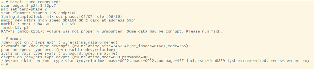
5.2.3 Using udev to automatically mount devices
Unlike mdev, udev uses a netlink mechanism to listen for uevent events sent by the kernel. Its event processing efficiency is higher, and it is typically used in larger systems, such as PCs. eudev is a fork of udev. According to some sources , udev has been merged into systemd, and eudev has become udev's successor, but it retains the udev name.
To use udev, you first need to compile the tool. In the expanded SDK directory, under osdrv/tools/board/eudev-3.2.7/ , first compile and build gperf-3.1 according to readme_cn.txt , then execute the compilation in the directory , and copy the compiled program to the corresponding directory of the root file system to complete the installation.make
For simplicity, this example will still use a single-partition TF card with a FAT32 file system inserted into the MMC1 card slot, automatically mounting the partition to the /mnt directory. First, ensure that udev is running (use psthe command to check), otherwise, use udevd --daemonthe command to start it.
Create a new rule file named 10-tfcard.rules in the directory /etc/udev/rules.d/ , with the following content:
ACTION=="add", KERNEL=="mmcblk1p1", RUN+="/etc/udev/mount-to-mnt.sh mmcblk1p1"
ACTION=="remove", KERNEL=="mmcblk1p1", RUN+="/etc/udev/umount-from-mnt.sh"
Create two new scripts, mount-to-mnt.sh and umount-from-mnt.sh , in the /etc/udev/ directory. Their contents are as follows:
# --mount-to-mnt.sh文件内容--
#!/bin/sh
mount -n /dev/$1 /mnt# --umount-from-mnt.sh文件内容--
#!/bin/sh
umount -l /mntSimply grant them executable permissions (hint: chmod +x mount-to-mnt.sh), and you can check the effect by accessing the /mnt directory before and after inserting and removing the TF card.
Risk: Because the mount point was not unmounted before removing the TF card umount, file system corruption or data loss may occur. A warning will be displayed on the next mount attempt.
FAT-fs (mmcblk1p1): Volume was not properly unmounted. Some data may be corrupt. Please run fsck.To implement multi-partition mounting, some modifications need to be made to the execution script, such as adding automatic creation/deletion of mount points, file system detection functionality, and exception handling. Given that this is only a "beginner's guide," further experimentation will not be undertaken.
6. Extended Exercises
This chapter records some content that goes beyond the scope of this introductory exercise. It may be of considerable reference value to your future studies. You can selectively browse it as needed, so that you won't feel unfamiliar when you actually use it later.
6.1 Building the root file system using Buildroot
Buildroot can be used to build a complete embedded system. It integrates a rich set of software packages and solves the installation dependencies of many applications, making it an essential tool for embedded engineers. This section uses the latest version of Buildroot at the time of writing: Buildroot-2021.11.2 . We will use this build tool to automate the construction of the root file system.
Download and extract Buildroot. Open the configuration interface in the terminal using make menuconfigthe command and make the following modifications:
- Target options
- Change the target architecture to ARM (little endian).
- Change the Target Architecture Variant to Cortex-A7
- Change Target ABI to EABI
- Modify the Floating point strategy to NEON/VFPv4
- Build options
- Modify the Kernel.org mirror in Mirrors and Download locations to "https://mirror.bjtu.edu.cn/kernel" to speed up downloads.
- Toolchain
- Change Toolchain type to External toolchain
- Change Toolchain to Custom toolchain
- Keep the toolchain origin as the pre-installed toolchain.
- Modify the Toolchain path to "/opt/hisi-linux/x86-arm/arm-himix200-linux"
- Change the Toolchain prefix to "arm-himix200-linux"
- Change the External toolchain gcc version to 6.x.
- Modify the External toolchain kernel headers series to 3.5.x.
- Modify the External toolchain C library to glibc/eglibc
- Does the selected Toolchain have C++ support?
- System configuration
- You can change the System hostname to a custom name, such as "Hi3516DV300".
- You can modify the system banner to a custom slogan or delete it.
- The on-demand configuration option for /dev management should be easy to understand given the experience gained in previous chapters.
- Configure the root password , such as "root".
- If you do not need to use Buildroot to compile the kernel , simply uncheck the Linux Kernel option. Otherwise, follow the steps below to configure Buildroot to compile the kernel provided by HiSilicon.
- Change the Kernel version to Custom version and populate the Kernel version field with "4.9.37".
- Enter the path to the patch file used in the Custom kernel patches section. For example, enter "/home/wind/buildroot-2021.11.2/linux-4.9.37.patch" here. This file can be obtained from the HiSilicon SDK.
- Modify the kernel configuration to use a custom (def)config file.
- Modify the Configuration file path to point to the path of the defconfig file you are using. For example, enter "/home/wind/buildroot-2021.11.2/hi3516dv300_emmc_smp_defconfig" here. This file can be obtained from the patched kernel.
- Change the kernel binary format to uImage
- Target packages can be selected as needed.
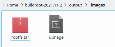
- Filesystem images
- Keep "tar the root filesystem" selected to generate the packaged root filesystem.
- U-Boot Bootloaders can use the version provided in the HiSilicon SDK, and since it involves DDR adaptation and other operations, there is no need to compile them manually.
- No action is required on the host utilities .
- No action is required for the Legacy config options .
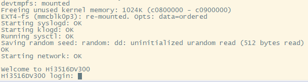
Save the settings and exit. Start makethe build process using [command/tool name - likely a command or tool], ensuring a stable network connection during the build. Once the build is complete, the kernel uImage image and the final root filesystem will be located in the output/inamges/ directory under the Buildroot directory.
The process of packaging and burning the file system image will not be described in detail.
The final startup result is shown in the image below. The root account password is the custom string used in the above build and configuration process.
6.2 Understanding the Device Tree
The device tree file for the Hi3516DV300 is located at arch/arm/boot/dts/hi3516dv300.dtsi in the kernel directory . The following are some comments about this file.
Tip: You can copy this content to other editors (such as Notepad++) to view it. It is recommended to use a monospaced font for display.
/*
* Copyright (c) 2013-2014 Linaro Ltd.
* Copyright (c) 2015-2017 HiSilicon Technologies Co., Ltd.
*
* 该程序是免费软件;您可以根据自由软件基金会发布的GNU通用
* 公共许可条款重新分发和/或修改它;许可证的第2版,或(由
* 您选择)任何更高版本。
*
* 分发此程序的目的是希望它有用,但不提供任何保证;甚至没
* 有对适销性或特定用途适用性的默示保证。有关详细信息,请
* 参阅GNU通用公共许可证。
*
* 您应该已经收到了一份GNU通用公共许可证的副本以及该程序。
* 如果没有,请参阅<http://www.gnu.org/licenses/>。
*
*/
#include <../../../../../include/generated/autoconf.h> |
#include "skeleton.dtsi" |
#include <dt-bindings/clock/hi3516dv300-clock.h> |定义了时钟节点ID,隶属CLK子系统
/ { |
aliases { |[aliases节点]仅用于为设备树中的节点起别名,
serial0 = &uart0; |别名可以被全设备树各处引用,方便客户快速
#ifndef CONFIG_ARCH_HISI_BVT_AMP |找到修改位置。
i2c0 = &i2c_bus0; |
i2c1 = &i2c_bus1; |
i2c2 = &i2c_bus2; | ↑
i2c3 = &i2c_bus3; |I2C节点别名
#endif | ↓
i2c4 = &i2c_bus4; |
i2c5 = &i2c_bus5; |
i2c6 = &i2c_bus6; |
i2c7 = &i2c_bus7; |
#ifndef CONFIG_ARCH_HISI_BVT_AMP |
spi0 = &spi_bus0; | ↑
spi1 = &spi_bus1; |SPI节点别名
spi2 = &spi_bus2; | ↓
#endif |
gpio0 = &gpio_chip0; |
gpio1 = &gpio_chip1; |
gpio2 = &gpio_chip2; |
gpio3 = &gpio_chip3; |
gpio4 = &gpio_chip4; |
gpio5 = &gpio_chip5; | ↑
gpio6 = &gpio_chip6; |GPIO节点别名
gpio7 = &gpio_chip7; | ↓
gpio8 = &gpio_chip8; |
gpio9 = &gpio_chip9; |
gpio10 = &gpio_chip10; |
gpio11 = &gpio_chip11; |
}; |
|
------------------------------------------------------------------------------------------------------------|
|
cpus { |[CPU节点]
#address-cells = <1>; |绝对起始地址本身所占字长为1,即u32
#size-cells = <0>; |reg所指地址空间大小所占字长为0,即仅当前地址位置
enable-method = "hisilicon,hi3516dv300"; |在arch/arm/mach-hibvt/mach-hi3516dv300.c
| ↓调用cpu初始化
cpu@0 { | arch/arm/mach-hibvt/platsmp.c
device_type = "cpu"; |
compatible = "arm,cortex-a7"; |
clock-frequency = <HI3516DV300_FIXED_1000M>; |
reg = <0>; |与#address-cells和#size-cells相对应,
}; |对于CPU不同核心分配不同的地址
#ifndef CONFIG_ARCH_HISI_BVT_AMP |注:默认情况下未配置CONFIG_ARCH_HISI_BVT_AMP
cpu@1 { |
device_type = "cpu"; |
compatible = "arm,cortex-a7"; |
clock-frequency = <HI3516DV300_FIXED_1000M>; |
reg = <1>; |
}; |
#endif |
}; |
|
clock: clock@12010000 { |[Clock Providers]隶属CLK子系统,提供PLL时钟分配,
compatible = "hisilicon,hi3516dv300-clock"; |在drivers/clk/hisilicon/clk-hi3516dv300.c中被调用,
#address-cells = <1>; |同时使用dt-bindings/clock/hi3516dv300-clock.h头文件。
#size-cells = <1>; |
#clock-cells = <1>; |时钟数量信息所占字长为1,即u32
|在drivers/clocksource/timer-hisp804.c(和其它?)中被判断。
#reset-cells = <2>; ?|
reg = <0x12010000 0x1000>; |CRG寄存器基址及对应寄存器空间(见用户指南-系统-时钟章节)
}; |与#address-cells和#size-cells相对应,各组中包含1+1个值,
|表示基址及从该基址处起多大的空间。后面不再解释。
|
gic: interrupt-controller@10300000 { |[GIC全局中断控制器]
compatible = "arm,cortex-a7-gic"; |
#interrupt-cells = <3>; |中断描述所需字长为3,即interrupts=<中断域 中断 触发方式>
#address-cells = <0>; | “中断域”,或作“中断类型”
interrupt-controller; |interrupt-controller空属性用于声明该节点接收中断,该角色
/* gic dist base, gic cpu base , no virtual support */ |负责收集各个外设的异步事件并通知processor。
reg = <0x10301000 0x1000>, <0x10302000 0x100>; |
}; |
|
syscounter { |[ARMv7通用定时器]
|可参见https://wiki.osdev.org/ARMv7_Generic_Timers
compatible = "arm,armv7-timer"; |
interrupt-parent = <&gic>; |此设备节点隶属于GIC中断控制器
interrupts = <1 13 0xf08>, |NOTE:当前设备树中仅此节点使用中断域1,其余节点均为中断域0
<1 14 0xf08>; |
clock-frequency = <50000000>; |工作时钟频率为50M
}; |
|
-----------------------------------------------------------|
|
soc { |[SoC节点]片内资源
#address-cells = <1>; |
#size-cells = <1>; |
compatible = "simple-bus"; |将该节点下的所有子节点都注册为platform device
interrupt-parent = <&gic>; |此设备节点隶属于GIC中断控制器
ranges; |地址空间1:1映射
|
clk_3m: clk_3m { |[3MHz固定时钟源]
compatible = "fixed-clock"; |主SOC子系统Timer的计数时钟可以选择为总线时钟
#clock-cells = <0>; |(50MHz)或3MHz时钟。(见用户指南-系统-定时器章节)
clock-frequency = <3000000>; |
}; |
|
clk_apb: clk_apb { |[50MHz固定总线时钟源]
compatible = "fixed-clock"; |APB(Advanced Peripheral Bus)高级外设总线,主要用来
#clock-cells = <0>; | 连接高性能低带宽的外围设备。
clock-frequency = <50000000>; |
}; |
|
pmu { |[电源管理单元]
compatible = "arm,cortex-a7-pmu"; |
interrupts = <0 54 4>; |<中断域0 中断号54 高电平触发>,后面不再解释。
}; |中断触发方式:
|1 上升沿触发
|2 下降沿触发
|4 高电平触发
|8 低电平触发
|
#ifdef CONFIG_HIEDMACV310 |注:默认情况下配置CONFIG_HIEDMACV310
hiedmacv310_0: hiedma-controller@10060000 { |[DMA控制器节点]负责处理UART0~4/I2C0~7/SPI0~2硬件请求
compatible = "hisilicon,hiedmacv310"; |驱动匹配位置:drivers/dma/hiedmacv310.c
reg = <0x10060000 0x1000>; |DMAC寄存器空间(见用户指南-系统-DMA控制器章节)
interrupts = <0 28 4>; |
clocks = <&clock HI3516DV300_DMAC_CLK>, <&clock HI3516DV300_DMAC_AXICLK>;
clock-names = "apb_pclk", "axi_aclk"; |
#clock-cells = <2>; |
resets = <&clock 0x194 0>; |DMAC相关的时钟及软复位控制寄存器(见用户指南CRG寄存器)
reset-names = "dma-reset"; |
dma-requests = <32>; |控制器支持的DMA请求信号数量(aka. 外设请求线)
dma-channels = <8>; |控制器支持的DMA通道数
devid = <0>; |设备ID,在Hi3516DV300中仅1个,其它芯片中可能有多个EDMAC
#dma-cells = <2>; |
status = "okay"; |状态:启用。
}; |
#endif |
#ifdef CONFIG_HIEDMAC |注:默认情况下未配置CONFIG_HIEDMAC
hiedmacv310_0: hiedma-controller@10060000 {
compatible = "hisilicon,hiedmacv310_n";
reg = <0x10060000 0x1000>;
interrupts = <0 28 4>;
clocks = <&clock HI3516DV300_DMAC_CLK>, <&clock HI3516DV300_DMAC_AXICLK>;
clock-names = "apb_pclk", "axi_aclk";
#clock-cells = <2>;
resets = <&clock 0x194 0>;
reset-names = "dma-reset";
dma-requests = <32>;
dma-channels = <8>;
devid = <0>;
#dma-cells = <2>;
status = "okay";
};
#endif
sysctrl: system-controller@12020000 { |[系统控制寄存器](见用户指南-系统-系统控制器章节)
compatible = "hisilicon,sysctrl"; |驱动匹配位置:drivers/irqchip/irq-gic.c
reg = <0x12020000 0x1000>; |
reboot-offset = <0x4>; |该偏移位置为系统软复位寄存器
#clock-cells = <1>; |
}; |
|
amba { |[AMBA总线]
#address-cells = <1>; |AMBA(Advanced Microcontroller Bus Architecture)
#size-cells = <1>; |高级微控制器总线架构
compatible = "arm,amba-bus"; |
ranges; |地址空间1:1映射
|
timer@hisp804 { |[定时器节点](见内核文档:arm,sp804.yaml)
compatible = "hisilicon,hisp804"; |驱动匹配位置:drivers/clocksource/timer-hisp804.c
/* timer0 & timer1 & timer2 */ |
reg = <0x12000000 0x20>, /* clocksource */ |定时器0用作时钟源
<0x12000020 0x20>, /* local timer for each cpu */ |定时器1用作CPU0时钟
<0x12001000 0x20>; |定时器2用作CPU1时钟
interrupts = <0 1 4>, /* irq of local timer */ |
<0 2 4>; |
clocks = <&clock HI3516DV300_FIXED_3M>, |
<&clock HI3516DV300_FIXED_3M>, |
<&clock HI3516DV300_FIXED_3M>; |3个定时器的时钟源均为3MHz时钟(非总线时钟)
clock-names = "timer0", "timer1", "timer2"; |
}; |
|
dual_timer2: dual_timer@12002000 { |[定时器节点](见内核文档:arm,sp804.yaml)
compatible = "arm,sp804", "arm,primecell"; |
/* timer4 & timer5 */ |使用定时器4、5(见用户指南-系统-定时器章节)
interrupts = <0 3 4>; |
reg = <0x12002000 0x1000>; |寄存器范围跨越Timer4和Timer5
clocks = <&clk_3m>, <&clk_3m>, <&clk_apb>; |
clock-names = "timer20", "timer21", "apb_pclk"; ?|同时使用了3M固定时钟源和50MHz总线时钟
status = "disabled"; |状态:禁用。后面不再解释。
}; |
|
uart0: uart@120a0000 { |[UART0节点]
compatible = "arm,pl011", "arm,primecell"; |驱动匹配位置:drivers/tty/serial/amba-pl011.c
reg = <0x120a0000 0x1000>; |
interrupts = <0 6 4>; |
clocks = <&clock HI3516DV300_UART0_CLK>; |
clock-names = "apb_pclk"; |使用50MHz总线时钟
status = "disabled"; |
}; |
|注意:这里未给UART0分配DMA请求编号。
|
#ifndef CONFIG_ARCH_HISI_BVT_AMP |
uart1: uart@120a1000 { |[UART1节点]
compatible = "arm,pl011", "arm,primecell"; |有关PL011的说明请自行查找《PrimeCell UART(PL011)》
reg = <0x120a1000 0x1000>; |
interrupts = <0 7 4>; |
clocks = <&clock HI3516DV300_UART1_CLK>; |
clock-names = "apb_pclk"; |
#ifdef CONFIG_HIEDMACV310 |
dmas = <&hiedmacv310_0 19 19>, <&hiedmacv310_0 18 18>; |分配DMA请求编号
dma-names = "tx","rx"; |(具体对应情况见用户指南-系统-DMA控制器章节)
#endif |
status = "disabled"; |
}; |
#endif |
uart2: uart@120a2000 { |[UART2节点]
compatible = "arm,pl011", "arm,primecell"; |
reg = <0x120a2000 0x1000>; |
interrupts = <0 8 4>; |
clocks = <&clock HI3516DV300_UART2_CLK>; |
clock-names = "apb_pclk"; |
#ifdef CONFIG_HIEDMACV310 |
dmas = <&hiedmacv310_0 21 21>, <&hiedmacv310_0 20 20>; |
dma-names = "tx","rx"; |
#endif |
status = "disabled"; |
}; |
|
uart3: uart@120a3000 { |[UART3节点]
compatible = "arm,pl011", "arm,primecell"; |
reg = <0x120a3000 0x1000>; |
interrupts = <0 9 4>; |
clocks = <&clock HI3516DV300_UART3_CLK>; |
clock-names = "apb_pclk"; |
#ifdef CONFIG_HIEDMACV310 |
dmas = <&hiedmacv310_0 23 23>, <&hiedmacv310_0 22 22>; |
dma-names = "tx","rx"; |
#endif |
status = "disabled"; |
}; |
|
uart4: uart@120a4000 { |[UART4节点]
compatible = "arm,pl011", "arm,primecell"; |
reg = <0x120a4000 0x1000>; |
interrupts = <0 10 4>; |
clocks = <&clock HI3516DV300_UART4_CLK>; |
clock-names = "apb_pclk"; |
#ifdef CONFIG_HIEDMACV310 |
dmas = <&hiedmacv310_0 25 25>, <&hiedmacv310_0 24 24>; |
dma-names = "tx","rx"; |
#endif |
status = "disabled"; |
}; |
|
}; |
|
#ifndef CONFIG_ARCH_HISI_BVT_AMP |
i2c_bus0: i2c@120b0000 { |[I2C0节点]
compatible = "hisilicon,hibvt-i2c"; |驱动匹配位置:drivers/i2c/busses/i2c-hibvt.c
reg = <0x120b0000 0x1000>; |
clocks = <&clock HI3516DV300_I2C0_CLK>; |
#ifdef CONFIG_HIEDMAC |
dmas = <&hiedmacv310_0 1 1>, <&hiedmacv310_0 0 0>; |
dma-names = "tx","rx"; |
#endif |
status = "disabled"; |
}; |
|
i2c_bus1: i2c@120b1000 { |[I2C1节点]
compatible = "hisilicon,hibvt-i2c"; |
reg = <0x120b1000 0x1000>; |
clocks = <&clock HI3516DV300_I2C1_CLK>; |
#ifdef CONFIG_HIEDMAC |
dmas = <&hiedmacv310_0 3 3>, <&hiedmacv310_0 2 2>; |
dma-names = "tx","rx"; |
#endif |
status = "disabled"; |
}; |
|
i2c_bus2: i2c@120b2000 { |[I2C2节点]
compatible = "hisilicon,hibvt-i2c"; |
reg = <0x120b2000 0x1000>; |
clocks = <&clock HI3516DV300_I2C2_CLK>; |
#ifdef CONFIG_HIEDMAC |
dmas = <&hiedmacv310_0 5 5>, <&hiedmacv310_0 4 4>; |
dma-names = "tx","rx"; |
#endif |
status = "disabled"; |
}; |
|
i2c_bus3: i2c@120b3000 { |[I2C3节点]
compatible = "hisilicon,hibvt-i2c"; |
reg = <0x120b3000 0x1000>; |
clocks = <&clock HI3516DV300_I2C3_CLK>; |
#ifdef CONFIG_HIEDMAC |
dmas = <&hiedmacv310_0 7 7>, <&hiedmacv310_0 6 6>; |
dma-names = "tx","rx"; |
#endif |
status = "disabled"; |
}; |
#endif |
i2c_bus4: i2c@120b4000 { |[I2C4节点]
compatible = "hisilicon,hibvt-i2c"; |
reg = <0x120b4000 0x1000>; |
clocks = <&clock HI3516DV300_I2C4_CLK>; |
#ifdef CONFIG_HIEDMAC |
dmas = <&hiedmacv310_0 9 9>, <&hiedmacv310_0 8 8>; |
dma-names = "tx","rx"; |
#endif |
status = "disabled"; |
}; |
|
i2c_bus5: i2c@120b5000 { |[I2C5节点]
compatible = "hisilicon,hibvt-i2c"; |
reg = <0x120b5000 0x1000>; |
clocks = <&clock HI3516DV300_I2C5_CLK>; |
#ifdef CONFIG_HIEDMAC |
dmas = <&hiedmacv310_0 11 11>, <&hiedmacv310_0 10 10>; |
dma-names = "tx","rx"; |
#endif |
status = "disabled"; |
}; |
|
i2c_bus6: i2c@120b6000 { |[I2C6节点]
compatible = "hisilicon,hibvt-i2c"; |
reg = <0x120b6000 0x1000>; |
clocks = <&clock HI3516DV300_I2C6_CLK>; |
#ifdef CONFIG_HIEDMAC |
dmas = <&hiedmacv310_0 13 13>, <&hiedmacv310_0 12 12>; |
dma-names = "tx","rx"; |
#endif |
status = "disabled"; |
}; |
|
i2c_bus7: i2c@120b7000 { |[I2C7节点]
compatible = "hisilicon,hibvt-i2c"; |
reg = <0x120b7000 0x1000>; |
clocks = <&clock HI3516DV300_I2C7_CLK>; |
#ifdef CONFIG_HIEDMAC |
dmas = <&hiedmacv310_0 15 15>, <&hiedmacv310_0 14 14>; |
dma-names = "tx","rx"; |
#endif |
status = "disabled"; |
}; |
|
#ifndef CONFIG_ARCH_HISI_BVT_AMP |
spi_bus0: spi@120c0000 { |[SPI0节点]
compatible = "arm,pl022", "arm,primecell"; |和PL011类似,PL022指代PrimeCell SPI。
arm,primecell-periphid = <0x00800022>; ?|
reg = <0x120c0000 0x1000>; |SPI0寄存器
interrupts = <0 68 4>; |
clocks = <&clock HI3516DV300_SPI0_CLK>; |
clock-names = "apb_pclk"; |使用50MHz总线时钟
#address-cells = <1>; |
#size-cells = <0>; |
#ifdef CONFIG_HIEDMACV310 |
dmas = <&hiedmacv310_0 27 27>, <&hiedmacv310_0 26 26>; |
dma-names = "tx","rx"; |
#endif |
status = "disabled"; |
}; |
|
spi_bus1: spi@120c1000 { |[SPI1节点]
compatible = "arm,pl022", "arm,primecell"; |
arm,primecell-periphid = <0x00800022>; |
reg = <0x120c1000 0x1000>, <0x12030000 0x4>; ?|暂不清楚为什么会用到0x12030000位置的MISC寄存器
interrupts = <0 69 4>; |
clocks = <&clock HI3516DV300_SPI1_CLK>; |
clock-names = "apb_pclk"; |
#address-cells = <1>; |
#size-cells = <0>; |
num-cs = <2>; |片选数量为2
hisi,spi_cs_sb = <2>; |驱动匹配位置:drivers/spi/spi-pl022.c
hisi,spi_cs_mask_bit = <0x4>;//0100 |驱动匹配位置:drivers/spi/spi-pl022.c
#ifdef CONFIG_HIEDMACV310 |
dmas = <&hiedmacv310_0 29 29>, <&hiedmacv310_0 28 28>; |
dma-names = "tx","rx"; |
#endif |
status = "disabled"; |
}; |
|
spi_bus2: spi@120c2000 { |[SPI2节点]
compatible = "arm,pl022", "arm,primecell"; |
arm,primecell-periphid = <0x00800022>; |
reg = <0x120c2000 0x1000>; |
interrupts = <0 70 4>; |
clocks = <&clock HI3516DV300_SPI2_CLK>; |
clock-names = "apb_pclk"; |
#address-cells = <1>; |
#size-cells = <0>; |
#ifdef CONFIG_HIEDMACV310 |
dmas = <&hiedmacv310_0 31 31>, <&hiedmacv310_0 30 30>; |
dma-names = "tx","rx"; |
#endif |
status = "disabled"; |
}; |
#endif |
|
ipcm: ipcm@045E0000 { |[IPCM节点]
compatible = "hisilicon,ipcm-interrupt"; ?|异构多核通信相关?
interrupt-parent = <&gic>; |
interrupts = <0 10 4>; |
reg = <0x10300000 0x4000>; |
status = "okay"; |
}; |
|
mdio0: mdio@10011100 { |[MDIO节点]
compatible = "hisilicon,hisi-femac-mdio"; |
reg = <0x10011100 0x10>; |MDIO控制寄存器
clocks = <&clock HI3516DV300_ETH0_CLK>; |
clock-names = "mdio"; |
assigned-clocks = <&clock HI3516DV300_ETH0_CLK>; |
assigned-clock-rates = <54000000>; |分配的时钟速率:54MHz
resets = <&clock 0x16c 3>; |
reset-names = "external-phy"; |驱动匹配位置:drivers/net/phy/mdio-hisi-femac.c
#address-cells = <1>; |
#size-cells = <0>; |
}; |
|
hisi_femac0: ethernet@10010000 { |[FEMAC节点]
compatible = "hisilicon,hi3516dv300-femac", |无驱动匹配位置(驱动中未添加hi3516dv300-femac)
"hisilicon,hisi-femac-v2"; |驱动匹配位置:drivers/net/ethernet/hisilicon/ \
reg = <0x10010000 0x1000>,<0x10011300 0x200>; |hisi-femac/hisi_femac.c
interrupts = <0 32 4>; |
clocks = <&clock HI3516DV300_ETH0_CLK>; |
resets = <&clock 0x16c 0>; |
reset-names = "mac"; |
}; |
|
fmc: flash-memory-controller@10000000 { |[闪存控制器节点]
compatible = "hisilicon,hisi-fmc"; |驱动匹配位置:drivers/mfd/hisi_fmc.c
reg = <0x10000000 0x1000>, <0x14000000 0x10000>; |FMC寄存器 & FMC存储空间(16M)
reg-names = "control", "memory"; |
clocks = <&clock HI3516DV300_FMC_CLK>; |
max-dma-size = <0x2000>; |
#address-cells = <1>; |
#size-cells = <0>; |
|
hisfc:spi-nor@0 { |
compatible = "hisilicon,fmc-spi-nor"; |驱动匹配位置:drivers/mfd/hisi_fmc.c
assigned-clocks = <&clock HI3516DV300_FMC_CLK>; |
assigned-clock-rates = <24000000>; |分配的时钟速率:24MHz
#address-cells = <1>; |
#size-cells = <0>; |
}; |
|
hisnfc:spi-nand@0 { |
compatible = "hisilicon,fmc-spi-nand"; |驱动匹配位置:drivers/mfd/hisi_fmc.c
assigned-clocks = <&clock HI3516DV300_FMC_CLK>; |
assigned-clock-rates = <24000000>; |分配的时钟速率:24MHz
#address-cells = <1>; |
#size-cells = <0>; |
}; |
}; |
|
mmc0: himci.eMMC@0x10100000 { |[MMC0-eMMC节点]
compatible = "hisilicon,hi3516dv300-himci"; |驱动匹配位置:drivers/mmc/host/himci/himci.c
reg = <0x10100000 0x1000>; |eMMC寄存器
interrupts = <0 64 4>; |
clocks = <&clock HI3516DV300_MMC0_CLK>; |
clock-names = "mmc_clk"; |
resets = <&clock 0x148 0>; |
reset-names = "mmc_reset"; |
max-frequency = <100000000>; |最大频率:100MHz
bus-width = <4>; |使用4线模式(未配置则为1线模式)
cap-mmc-highspeed; |标识此槽位支持高速MMC
cap-mmc-hw-reset; |标识此槽位支持硬件复位
mmc-hs200-1_8v; |MMC高速200M_1.8V供电电压
devid = <0>; |
status = "disabled"; |
}; |
|
mmc1: himci.SD@0x100f0000 { |[MMC1-SD节点]
compatible = "hisilicon,hi3516dv300-himci"; |
reg = <0x100f0000 0x1000>; |
interrupts = <0 30 4>; |
clocks = <&clock HI3516DV300_MMC1_CLK>; |
clock-names = "mmc_clk"; |
resets = <&clock 0x160 0>; |
reset-names = "mmc_reset"; |
max-frequency = <100000000>; |
bus-width = <4>; |
cap-sd-highspeed; |标识此槽位支持高速SD卡
sd-uhs-sdr12; |超高速卡支持12MB/s总线速度
sd-uhs-sdr25; |超高速卡支持25MB/s总线速度
sd-uhs-sdr50; |超高速卡支持50MB/s总线速度
sd-uhs-sdr104; |超高速卡支持104MB/s总线速度
full-pwr-cycle; |支持设备卡的整个电源周期
devid = <1>; |
status = "disabled"; |
}; |
|
mmc2: himci.SD@0x10020000 { |[MMC2-SD节点]
compatible = "hisilicon,hi3516dv300-himci"; |
reg = <0x10020000 0x1000>; |
interrupts = <0 31 4>; |
clocks = <&clock HI3516DV300_MMC2_CLK>; |
clock-names = "mmc_clk"; |
resets = <&clock 0x154 0>; |
reset-names = "mmc_reset"; |
max-frequency = <100000000>; |
bus-width = <4>; |
cap-sd-highspeed; |
sd-uhs-sdr12; |
sd-uhs-sdr25; |
sd-uhs-sdr50; |
sd-uhs-sdr104; |
full-pwr-cycle; |
devid = <2>; |
status = "disabled"; |
}; |
|
hidmac: hidma-controller@10060000 { |[DMAC节点]
compatible = "hisilicon,hisi-dmac"; |驱动匹配位置:drivers/hidmac/hi_pl08x.c
reg = <0x10060000 0x1000>; |
interrupts = <0 28 4>; |
clocks = <&clock HI3516DV300_DMAC_CLK>; |
clock-names = "dmac_clk"; |
resets = <&clock 0xc8 4>; |
reset-names = "dma-reset"; |
#dma-cells = <2>; |
status = "disabled"; |
}; |
|
usb_phy: phy { |[USB_PHY节点]
compatible = "hisilicon,hisi-usb-phy"; |驱动匹配位置:drivers/phy/hibvt/phy-hisi-usb.c
reg = <0x12010000 0x1000>; |CRG寄存器基址及对应寄存器空间
#phy-cells = <0>; |
}; |
|
#define USB_HOST 1 |
#if USB_HOST |
xhci_0@0x100e0000 { |[XHCI节点]xHCI主机控制器
compatible = "generic-xhci"; |
reg = <0x100e0000 0x10000>; |USB控制寄存器
interrupts = <0 27 4>; |
usb2-lpm-disable; |禁用USB2.0链路电源管理
}; |
#else |
hidwc3_0@0x100e0000 { |[DWC3节点]
compatible = "snps,dwc3"; |DesignWare Core SuperSpeed USB 3.0 Controller
reg = <0x100e0000 0x10000>; |
interrupts = <0 27 4>; |
interrupt-names = "peripheral"; |
maximum-speed = "high-speed"; |
dr_mode = "peripheral"; |
}; |
#endif |
gpio_chip0: gpio_chip@120d0000 { |[GPIO0节点]
compatible = "arm,pl061", "arm,primecell"; |和PL011/PL022类似,有关PL061的信息请自行查找
reg = <0x120d0000 0x1000>; |《General Purpose Input/Output(PL061)》。
interrupts = <0 16 4>; |注意:该中断号非中断源编号
clocks = <&clock HI3516DV300_SYSAPB_CLK>; |
clock-names = "apb_pclk"; |使用50MHz总线时钟
#gpio-cells = <2>; |该控制器下每个引脚需使用2个u32描述。
status = "disabled"; |
}; |
|
gpio_chip1: gpio_chip@120d1000 { |[GPIO1节点]
compatible = "arm,pl061", "arm,primecell"; |
reg = <0x120d1000 0x1000>; |
interrupts = <0 17 4>; |
clocks = <&clock HI3516DV300_SYSAPB_CLK>; |
clock-names = "apb_pclk"; |
#gpio-cells = <2>; |
status = "disabled"; |
}; |
|
gpio_chip2: gpio_chip@120d2000 { |[GPIO2节点]
compatible = "arm,pl061", "arm,primecell"; |
reg = <0x120d2000 0x1000>; |
interrupts = <0 18 4>; |
clocks = <&clock HI3516DV300_SYSAPB_CLK>; |
clock-names = "apb_pclk"; |
#gpio-cells = <2>; |
status = "disabled"; |
}; |
|
gpio_chip3: gpio_chip@120d3000 { |[GPIO3节点]
compatible = "arm,pl061", "arm,primecell"; |
reg = <0x120d3000 0x1000>; |
interrupts = <0 19 4>; |
clocks = <&clock HI3516DV300_SYSAPB_CLK>; |
clock-names = "apb_pclk"; |
#gpio-cells = <2>; |
status = "disabled"; |
}; |
|
gpio_chip4: gpio_chip@120d4000 { |[GPIO4节点]
compatible = "arm,pl061", "arm,primecell"; |
reg = <0x120d4000 0x1000>; |
interrupts = <0 20 4>; |
clocks = <&clock HI3516DV300_SYSAPB_CLK>; |
clock-names = "apb_pclk"; |
#gpio-cells = <2>; |
status = "disabled"; |
}; |
|
gpio_chip5: gpio_chip@120d5000 { |[GPIO5节点]
compatible = "arm,pl061", "arm,primecell"; |
reg = <0x120d5000 0x1000>; |
interrupts = <0 21 4>; |
clocks = <&clock HI3516DV300_SYSAPB_CLK>; |
clock-names = "apb_pclk"; |
#gpio-cells = <2>; |
status = "disabled"; |
}; |
|
gpio_chip6: gpio_chip@120d6000 { |[GPIO6节点]
compatible = "arm,pl061", "arm,primecell"; |
reg = <0x120d6000 0x1000>; |
interrupts = <0 22 4>; |
clocks = <&clock HI3516DV300_SYSAPB_CLK>; |
clock-names = "apb_pclk"; |
#gpio-cells = <2>; |
status = "disabled"; |
}; |
|
gpio_chip7: gpio_chip@120d7000 { |[GPIO7节点]
compatible = "arm,pl061", "arm,primecell"; |
reg = <0x120d7000 0x1000>; |
interrupts = <0 23 4>; |
clocks = <&clock HI3516DV300_SYSAPB_CLK>; |
clock-names = "apb_pclk"; |
#gpio-cells = <2>; |
status = "disabled"; |
}; |
|
gpio_chip8: gpio_chip@120d8000 { |[GPIO8节点]
compatible = "arm,pl061", "arm,primecell"; |
reg = <0x120d8000 0x1000>; |
interrupts = <0 24 4>; |
clocks = <&clock HI3516DV300_SYSAPB_CLK>; |
clock-names = "apb_pclk"; |
#gpio-cells = <2>; |
status = "disabled"; |
}; |
|
gpio_chip9: gpio_chip@120d9000 { |[GPIO9节点]
compatible = "arm,pl061", "arm,primecell"; |
reg = <0x120d9000 0x1000>; |
interrupts = <0 25 4>; |
clocks = <&clock HI3516DV300_SYSAPB_CLK>; |
clock-names = "apb_pclk"; |
#gpio-cells = <2>; |
status = "disabled"; |
}; |
|
gpio_chip10: gpio_chip@120da000 { |[GPIO10节点]
compatible = "arm,pl061", "arm,primecell"; |
reg = <0x120da000 0x1000>; |
interrupts = <0 26 4>; |
clocks = <&clock HI3516DV300_SYSAPB_CLK>; |
clock-names = "apb_pclk"; |
#gpio-cells = <2>; |
status = "disabled"; |
}; |
|
gpio_chip11: gpio_chip@120db000 { |[GPIO11节点]
compatible = "arm,pl061", "arm,primecell"; |
reg = <0x120db000 0x1000>; |
interrupts = <0 80 4>; |
clocks = <&clock HI3516DV300_SYSAPB_CLK>; |
clock-names = "apb_pclk"; |
#gpio-cells = <2>; |
status = "disabled"; |
}; |
|
cipher: cipher@0x100c0000 { |[加密器节点]
compatible = "hisilicon,hisi-cipher"; |驱动位置:drivers/crypto/hisi-cipher/目录下
reg = <0x100c0000 0x10000>; |
reg-names = "cipher"; |
interrupts = <0 71 4>, <0 72 4>, <0 71 4>, <0 72 4>; ?|
interrupt-names = "cipher", "nonsec_cipher", "hash", "nonsec_hash";
};
};
----------------------------------------------------------------------------------|
|
media { |[Media节点]
#address-cells = <1>; |该节点下的子节点为海思MPP相关模块,
#size-cells = <1>; |无需也无法做什么特定的分析,且节点
compatible = "simple-bus"; |信息较为简单,故略过注释。
...
}The annotations above are actually notes I jotted down while studying, and I'm not entirely clear on the details, but this is all I can do for now. If there are any errors, I hope they won't mislead the reader.
6.3 Connecting the Development Board Partition to the PC using a USB Gadget
The kernel configuration provided by the SDK has already enabled support for USB Gadget drivers for mass storage devices. You only need to change the USB controller to device mode to use it.
Use menu config the configured kernel:
make ARCH=arm CROSS_COMPILE=arm-himix200-linux- menuconfigMake the following modifications to change the USB controller from host mode to slave mode:
- Device Drivers -> PHY Subsystem -> Hisilicon USB related configuration
- Cancel USB DRD0 Mode Select HOST
- Select USB DRD0 Mode.
Save and recompile the kernel, burn the generated uImage to the board, and copy the kernel module driver to the corresponding directory of the root file system as described above.
[Regarding USB Controller Mode Selection] Referring to the relevant chapters on USB DRD in the "Hi3516DV300 Professional Smart IP Camera SoC User Guide," the USB DRD supports independent operation in Host or Device mode but does not support OTG. Also, referring to the relevant nodes in the device tree, if both Master and Slave modes are selected in the above kernel configuration, because the Master and Slave device node addresses are the same, the later matched driver will overwrite the previous register settings, and the device will operate in Slave mode.
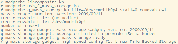
After booting into the system, execute the following command to mount the USB Gadget driver. Using the partition table used in section 3.2.1 eMMC storage partitioning as an example, specify partition 4 as the mount partition:
modprobe libcomposite.ko
modprobe usb_f_mass_storage.ko
modprobe g_mass_storage.ko file=/dev/mmcblk0p4 stall=0 removable=1
[Source of related .ko files] Before mounting the .ko files, you need to copy the compiled module files to the specified directory on the development board as described in sections 2.4 Kernel Compilation and 2.5 Root File System Creation
modprobe; otherwise, these modules will not be found.
The following message indicates that the operation was successful:
[Prompt when USB controller mode is not switched] If the USB DRD's operating mode is not switched to slave mode in the kernel or device tree, the following message will be displayed when mounting the above ko module:

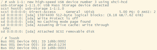
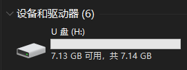
Once the development board is connected to a PC via USB, it will be recognized as a USB flash drive, and operations such as formatting and reading/writing can be performed on the USB flash drive.
[File System Support] In Linux, you can use
cat /proc/filesystemsthe command to view the file systems currently supported by the kernel. Selecting a file system that is supported by both the PC and the onboard Linux allows the partition to be accessed by both at the same time. For example, you can format it as FAT32 in Windows , but you should be aware of potential synchronization issues.
6.4 Using FBTFT – SPI Peripherals and Linux FB
6.4.1 OLED12864 and FBTFT Driver
The OLED12864 is a common display module, and its driver IC is the SSD1306/SSD1315, etc. If you have experience with microcontrollers and have used this screen, you will easily understand that displaying essentially involves writing to the internal registers of the SSD1306. In a Linux environment, drivers and applications are separate: drivers are mounted to the kernel and communicate with the underlying devices; applications access drivers through system-provided interfaces to control hardware devices.
[Note] FBTFT only supports screens with an SPI interface. The OLED12864 has various interface versions, such as SPI, IIC, and parallel port, depending on the control IC and hardware design. Please pay attention to this when purchasing. This section uses a monochrome screen driven by an SSD1306 as an example. If your driver IC differs from the one described, please refer to the following description for adaptation.
[Supplement] The fact that the FBTFT driver is listed as Staging indicates that the FB mechanism will be deprecated in later versions and replaced by DRM.
6.4.2 Add SSD1306 driver support to the kernel
Linux 4.9.37 already includes the TFTFB driver; you only need to enable support for SSD1306 in the kernel.
[Note] To prevent operation failure, the following modifications are based on the 2.4 Kernel compilation section.
Use menuconfigthe configured kernel:
make ARCH=arm CROSS_COMPILE=arm-himix200-linux- menuconfigMake the following modifications:
- Device Drivers
- Select SPI support
- Select Staging drivers
- Device Drivers -> Staging drivers
- Select "Support for small TFT LCD display modules" and compile it into the kernel.
- Device Drivers -> Staging drivers -> Support for small TFT LCD display modules
- Select the FB driver for the SSD1306 OLED Controller and compile it as a module.
- Select the Generic FB driver for TFT LCD displays and compile it as a module.
- Select "Module to for adding FBTFT devices " to compile it as a module.
[Kernel Configuration Notes] The reason for configuring the driver as a module instead of compiling it directly into the kernel is that we did not manage to configure the pin multiplexing of the corresponding GPIO at the initial stage of system startup. This would affect the device initialization process. Manual mounting would not have this problem.
Then, the device tree was modified to add device information to the SPI node location where the hardware is connected.
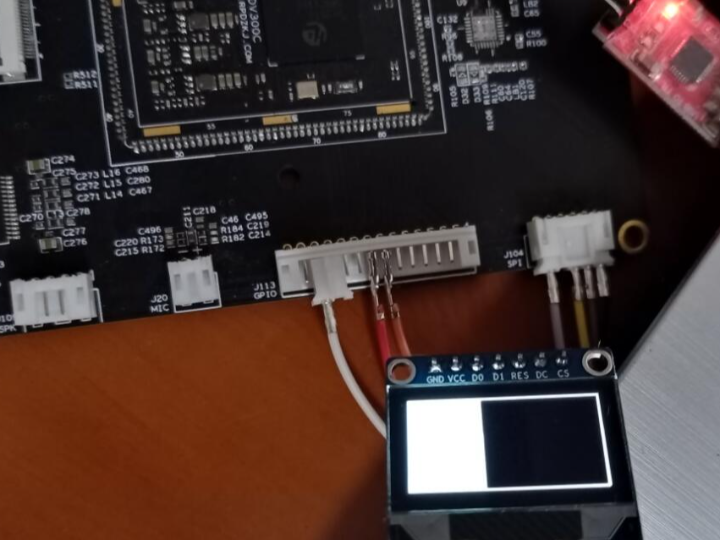
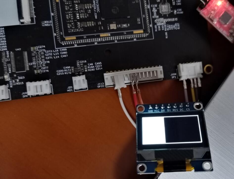
[Pin Connection Instructions] On the development board used for testing, connect the OLED12864 to SPI1. The relevant pins of SPI1 and the GPIO control pins used by the OLED12864 in the test are shown in the table below. Please refer to the schematic diagram of your hardware to solder the components yourself. Functional Chip Pins Development Board Pins OLED12864 Module Silkscreen SPI1_CS(0) D18 SPI1_CSN0/GPIO8_2 CS SPI1_MOSI E19 SPI1_SDO/GPIO8_1 D1 SPI1_CLK F19 SPI1_SCLK/GPIO8_0 D0 SPI1_MISO F18 SPI1_SDI/GPIO8_3 No GPIO H18 GPIO10_6 DC GPIO J18 GPIO10_7 RST Module power supply can be 3.3V.
Modify ./arch/arm/boot/dts/hi3516dv300-demb.dts and add an OLED12864 connection description to the SPI1 node:
&spi_bus1{

status = "okay";
num-cs = <2>;
/* spidev@0 { compatible = "rohm,dh2228fv"; reg = <0>; pl022,interface = <0>; pl022,com-mode = <0>; spi-max-frequency = <50000000>; }; */
ssd1306@0 {

compatible = "solomon,ssd1306";
reg = <0>;
spi-max-frequency = <50000000>;
buswidth = <8>;
dc-gpios = <&gpio_chip10 6 0>;
reset-gpios = <&gpio_chip10 7 0>;
};
spidev@1 {

compatible = "rohm,dh2228fv";
reg = <1>;
pl022,interface = <0>;
pl022,com-mode = <0>;
spi-max-frequency = <50000000>;
};
};
The meaning and usage of each attribute can be found in the ./drivers/staging/fbtft/fbtft_device.c file in the kernel source code directory.
[Note] If the connection between the module and the development board is not stable enough, a high clock speed may cause signal distortion.
After the modifications are complete, the kernel and device tree are recompiled and flashed to the board. At the same time, the corresponding kernel modules are installed to the corresponding locations in the root file system.
After entering the development board system, first use the following commands to change the multiplexing status of the corresponding pins, the GPIO direction, and set the pull-up pins:
devmem 0x112F0020 32 0x501
devmem 0x112F0024 32 0x501
devmem 0x112F0028 32 0x501
devmem 0x112F002C 32 0x501
devmem 0x112F0000 32 0x500
devmem 0x112F0004 32 0x500
devmem 0x120DA400 8 0xC0
Ensure the module is in the correct location, then execute the following command in the shell to mount the driver:
modprobe fb_ssd1306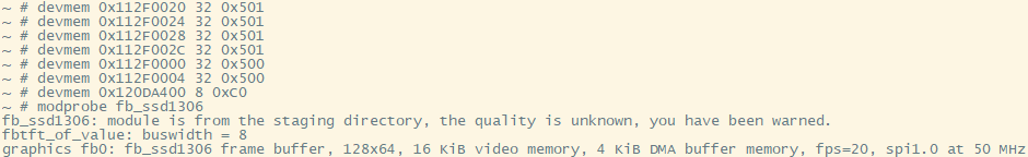
The driver will register the frame buffer device, and the fb0 device node will appear in the /dev/ directory .
6.4.3 Basic Use of FB Devices
"FB" stands for "FrameBuffer," which is an interface provided by Linux for display devices. It maps video memory to a contiguous address space, converting operations on the display device into read and write operations on memory, greatly facilitating the process of window graphics drawing in applications. Linux FB is an essential concept to understand.
The basic steps for using an FB device are: turn on the device -> query information and configure the device -> memory mapping -> read and write the mapped frame buffer -> unmap -> turn off the device.
The example program is as follows.
//+------------------------------------------------------------------------------------------+
//| 前言
//+------------------------------------------------------------------------------------------+
//| FrameBuffer(帧缓冲)设备是Linux为显示设备提供的一个接口,它将显存映射为一片连续的地
//| 址空间,将对显示设备的操作转换为对内存的读写,极大地方便了应用程序进行窗口图形绘制的过程。
//+------------------------------------------------------------------------------------------+
//| 文件说明
//+------------------------------------------------------------------------------------------+
//| 本程序基于的硬件为Hi3516DV300+OLED12864(SSD1306 SPI)。程序打开/dev/fb0设备,获取设备
//| 相关的信息打印到标准输出,并执行一些绘制操作,而后关闭设备并退出。
//+------------------------------------------------------------------------------------------+
//| 头文件包含
//+------------------------------------------------------------------------------------------+
/*|*/#include <stdio.h>
/*|*/#include <stdlib.h>
/*|*/#include <stdbool.h>
/*|*/#include <stdint.h>
/*|*/#include <signal.h>
/*|*/#include <unistd.h>
/*|*/#include <pthread.h>
/*|*/#include <fcntl.h>
/*|*/#include <linux/fb.h> //提供对Linux FB操作支持
/*|*/#include <sys/mman.h>
/*|*/#include <sys/ioctl.h>
//+------------------------------------------------------------------------------------------+
//| 全局变量
//+------------------------------------------------------------------------------------------+
//| ----------------------------------------
//| [说明]
//| fbtft_fd: FB设备文件描述符
//| fbtft_p : 显示缓冲区映射地址
//| ----------------------------------------
/*|*/static int fbtft_fd = -1;
/*|*/static char *fbtft_p = NULL;
//| ----------------------------------------
//| [说明]以下两个结构体分别保存获取的fb设备
//| 的可变信息和不可变信息。
//| ----------------------------------------
/*|*/struct fb_var_screeninfo fbtft_variable_info;
/*|*/struct fb_fix_screeninfo fbtft_fixed_info;
//+------------------------------------------------------------------------------------------+
//| 函数名称:signal_handle
//| 功能描述:信号处理
//| 参数说明:信号标号
//| 返回值说明:无
//| 备注:
//+------------------------------------------------------------------------------------------+
static void signal_handle(int signo)
{

if(SIGINT == signo || SIGTERM == signo)
{

exit(1);
}
}
//+------------------------------------------------------------------------------------------+
//| 函数名称:usage
//| 功能描述:打印使用说明
//| 参数说明:无
//| 返回值说明:无
//| 备注:
//+------------------------------------------------------------------------------------------+
static void usage(void)
{

printf("Usage:\n");
printf("This program obtains relevant information and draws a frame on the Linux FB device (OLED12864).\n");
printf("The program is only suitable for the screen driven by SSD1306, 16 bytes_per_pixel.\n");
printf("Author:Linyar Version:STv13 E-mail:WindForest@yeah.net\n");
printf("[NOTICE]Input Ctrl+C to stop program.\n");
}
//+------------------------------------------------------------------------------------------+
//| 函数名称:calculate_location
//| 功能描述:计算一个像素点在显示缓冲区中的位置
//| 参数说明:像素点自左上至右下,以0起始的坐标
//| 返回值说明:像素在缓冲区中的偏移位置
//| 备注:
//+------------------------------------------------------------------------------------------+
static int calculate_location(uint32_t _x, uint32_t _y)
{

int bytes_per_pixel = fbtft_variable_info.bits_per_pixel / 8;
return (_x * bytes_per_pixel + _y * fbtft_variable_info.xres * bytes_per_pixel);
}
//+------------------------------------------------------------------------------------------+
//| 函数名称:draw_point
//| 功能描述:绘制某个点
//| 参数说明:位置和填充。pad:1表示点亮像素,0表示熄灭像素
//| 返回值说明:成功返回0
//| 备注:[注意]当前画点函数仅适用16bit的bytes_per_pixel。
//+------------------------------------------------------------------------------------------+
static int draw_point(uint32_t _x, uint32_t _y, bool pad)
{

if(fbtft_p == NULL)
{

return -1;
}
if(_x > fbtft_variable_info.xres || _y > fbtft_variable_info.yres)
{

printf("Illegal coordinates: %d*%d!\n", _x, _y);
return -2;
}
long position = calculate_location(_x, _y);
if(pad)
{

*(fbtft_p + position) = 0xFF;
*(fbtft_p + position + 1) = 0xFF;
}
else
{

*(fbtft_p + position) = 0x00;
*(fbtft_p + position + 1) = 0x00;
}
return 0;
}
//+------------------------------------------------------------------------------------------+
//| 函数名称:main
//| 功能描述:主函数
//| 参数说明:略
//| 返回值说明:成功返回0
//| 备注:
//+------------------------------------------------------------------------------------------+
int main(int argc, const char *argv[])
{

signal(SIGINT,  signal_handle);
signal(SIGTERM, signal_handle);
/* 打印程序说明 */
usage();
/* 打开Linux FB设备 */
fbtft_fd = open("/dev/fb0", O_RDWR);
if(fbtft_fd < 0)
{

printf("Open FB device failed with %d!\n", fbtft_fd);
goto EXIT;
}
/* 获取设备信息 */
if(ioctl(fbtft_fd, FBIOGET_FSCREENINFO, &fbtft_fixed_info) != 0)
{

printf("Get FB device's fixed info failed!\n");
goto END_0;
}
if(ioctl(fbtft_fd, FBIOGET_VSCREENINFO, &fbtft_variable_info) != 0)
{

printf("Get FB device's variable info failed!\n");
goto END_0;
}
/* 展示设备主要信息 */
printf("+----------------FB Device's Fixed Info-------------------+\n");
printf("|Identification: %s\n"         , fbtft_fixed_info.id          );
printf("|Physical mem start at 0x%lx\n", fbtft_fixed_info.smem_start  );
printf("|Physical mem length: %d\n"    , fbtft_fixed_info.smem_len    );
printf("|Line length: %d\n"            , fbtft_fixed_info.line_length );
printf("|Mapped mem start at 0x%lx\n"  , fbtft_fixed_info.mmio_start  );
printf("|Mapped mem length: %d\n"      , fbtft_fixed_info.mmio_len    );
printf("|type : %d\n"              , fbtft_fixed_info.type        );
printf("|type_aux : %d\n"              , fbtft_fixed_info.type_aux    );
printf("|visual : %d\n"              , fbtft_fixed_info.visual      );
printf("|xpanstep : %d\n"              , fbtft_fixed_info.xpanstep    );
printf("|ypanstep : %d\n"              , fbtft_fixed_info.ypanstep    );
printf("|ywrapstep: %d\n"              , fbtft_fixed_info.ywrapstep   );
printf("|accel : %d\n"              , fbtft_fixed_info.accel       );
printf("+---------------FB Device's Variable Info-----------------+\n");
printf("|Visible resolution: %d*%d\n"  , fbtft_variable_info.xres, fbtft_variable_info.yres);
printf("|Virtual resolution: %d*%d\n"  , fbtft_variable_info.xres_virtual, fbtft_variable_info.yres_virtual);
printf("|X offset from virtual to visible: %d\n", fbtft_variable_info.xoffset);
printf("|Y offset from virtual to visible: %d\n", fbtft_variable_info.yoffset);
printf("|bits_per_pixel: %d\n"    , fbtft_variable_info.bits_per_pixel);
printf("|grayscale : %d\n"    , fbtft_variable_info.grayscale     );
printf("|nonstd : %d\n"    , fbtft_variable_info.nonstd        );
printf("|activate : %d\n"    , fbtft_variable_info.activate      );
printf("|height : %d\n"    , fbtft_variable_info.height        );
printf("|width : %d\n"    , fbtft_variable_info.width         );
printf("|accel_flags : %d\n"    , fbtft_variable_info.accel_flags   );
printf("|pixclock : %d\n"    , fbtft_variable_info.pixclock      );
printf("|left_margin : %d\n"    , fbtft_variable_info.left_margin   );
printf("|right_margin : %d\n"    , fbtft_variable_info.right_margin  );
printf("|upper_margin : %d\n"    , fbtft_variable_info.upper_margin  );
printf("|lower_margin : %d\n"    , fbtft_variable_info.lower_margin  );
printf("|hsync_len : %d\n"    , fbtft_variable_info.hsync_len     );
printf("|vsync_len : %d\n"    , fbtft_variable_info.vsync_len     );
printf("|sync : %d\n"    , fbtft_variable_info.sync          );
printf("|vmode : %d\n"    , fbtft_variable_info.vmode         );
printf("|rotate : %d\n"    , fbtft_variable_info.rotate        );
printf("+---------------------------------------------------------+\n");
/* 映射并获取FB设备操作地址 */
long screensize = 0;
screensize = fbtft_variable_info.xres * fbtft_variable_info.yres * fbtft_variable_info.bits_per_pixel / 8;
fbtft_p = (char *)mmap(0, screensize, PROT_READ|PROT_WRITE, MAP_SHARED, fbtft_fd, 0);
if((int)fbtft_p == -1)
{

printf("Mmap FB device's mem space failed with %d!\n", (int)fbtft_p);
goto END_0;
}
//绘制边框
for(int i = 0; i < fbtft_variable_info.xres; i++)
{

draw_point(i, 0, 1);
draw_point(i, fbtft_variable_info.yres - 1, 1);
}
for(int i = 1; i < fbtft_variable_info.yres - 1; i++)
{

draw_point(0, i, 1);
draw_point(fbtft_variable_info.xres - 1, i, 1);
}
//填充测试
int k = 3;
while(k != 0)
{

for(int j = 1; j < fbtft_variable_info.xres - 1; j++)
{

for(int i = 1; i < fbtft_variable_info.yres - 1; i++)
{

draw_point(j, i, k % 2);
}
usleep(10000);
}
k--;
}
munmap(fbtft_p, screensize);
END_0:
close(fbtft_fd);
EXIT:
return 0;
}
Save the code as fbtft_ssd1306_test.c , then compile it in the development environment arm-himix200-linux-gcc -o fbtft_ssd1306_test fbtft_ssd1306_test.c, grant executable permissions, and then run the generated fbtft_ssd1306_test program on the board.
6.4.4 Mapping the terminal to the screen
After completing the above steps, perform the following additional configuration in the kernel:
- Device Drivers -> Graphics support -> Console display driver support
- Select Framebuffer Console support
- Select Map the console to the primary display device
Recompile the kernel and flash it.
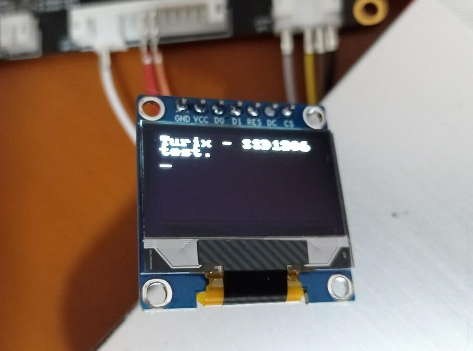
After correctly configuring pin multiplexing and attaching the driver, a blinking cursor will be visible on the screen. You can echotest this using commands such as:
echo "Turix - SSD1306 test." > /dev/tty0You can then see the printed output on the screen.
[Instructions - Turn off screen cursor & blinking] During kernel configuration, perform the following steps:
- Enable General setup -> Configure standard kernel features (expert users)
- Disable Device Driver -> Graphics support -> Console display driver support -> Framebuffer Console support
Alternatively, execute the following commands after startup: `echo 0 > /sys/class/graphics/fbcon/cursor_blink` and `echo 0 > /sys/class/vtconsole/vtcon1/bind`. The former will disable cursor blinking, and the latter will disable terminal mapping.
[Instructions - Uninstalling fb_ssd1306 driver] Terminal mapping must be closed before uninstallation, otherwise a resource usage error will be displayed
rmmod: can't unload module 'fb_ssd1306': Resource temporarily unavailable.
7 Unsuccessful attempts
This chapter records some practical aspects that the author only dabbled in and ultimately did not fully complete.
7.1 W5500 and Wired Network
Note: There are unresolved issues in this chapter.
7.1.1 W5500 Ethernet Controller
The W5500 is one product in a series that includes models such as the W5100S, W5200, W5300, and W5500. Differences between these models can be found in their respective datasheets. Unlike typical Ethernet PHY chips, these Ethernet controllers have a built-in TCP /IP protocol stack, making them more suitable for resource-constrained MCUs such as microcontrollers. Linux itself has a complete TCP/IP implementation, and SoCs typically integrate the Ethernet controller internally, eliminating the need for an external chip.
7.1.2 Add W5500 driver support to the kernel
Linux 4.9.37 already includes the W5500 driver, so you only need to enable support for W5500 in the kernel.
Use menuconfigthe configured kernel:
make ARCH=arm CROSS_COMPILE=arm-himix200-linux- menuconfigMake the following modifications:
- Device Drivers -> Network device support
- Select Ethernet driver support
- Device Drivers -> Network device support -> Ethernet driver support
- Select WIZnet devices
- Device Drivers -> Network device support -> Ethernet driver support -> WIZnet W5100 Ethernet support
- Select the WIZnet W5100 Ethernet support item and its sub-item WIZnet W5100/W5200/W5500 Ethernet support for SPI mode , and compile it as a module.
- Device Drivers -> GPIO Support -> Memory mapped GPIO drivers
- Unselect PrimeCell PL061 GPIO support
[Kernel Configuration Notes] The reason for configuring the driver as a module instead of compiling it directly into the kernel is that we did not manage to configure the pin multiplexing of the corresponding GPIO at the initial stage of system startup. This would affect the device initialization process. Manual mounting would not have this problem.
Then, the device tree was modified to add device information to the SPI node location where the hardware is connected.
[Pin Connection Instructions] On the development board used for testing, connect the W5500 to SPI1. The relevant pins of SPI1 and the GPIO control pins used by the W5500 in the test are shown in the table below. Please refer to the schematic diagram of your hardware to solder the components yourself. Functional Chip Pins Development Board Pins W5500 Pins SPI1_CS(0) D18 SPI1_CSN0/GPIO8_2 SCS SPI1_MOSI E19 SPI1_SDO/GPIO8_1 MOSI SPI1_CLK F19 SPI1_SCLK/GPIO8_0 SCLK SPI1_MISO F18 SPI1_SDI/GPIO8_3 MISO GPIO H18 GPIO10_6 INT In the W5500 driver, register operation is used for reset, so there is no need to connect the RST pin. The module can be powered by 3.3V.
Modify ./arch/arm/boot/dts/hi3516dv300-demb.dts and add a W5500 connection description to the SPI1 node:
&spi_bus1{
status = "okay";
num-cs = <2>;
/*
spidev@0 {
compatible = "rohm,dh2228fv";
reg = <0>;
pl022,interface = <0>;
pl022,com-mode = <0>;
spi-max-frequency = <50000000>;
};
*/
w5500@0{
compatible = "w5500";
reg = <0>;
interrupt-parent = <&gic>;
interrupts = <0 26 4>; /* 58-32=26 */
gpios = <&gpio_chip10 6 0>;
spi-max-frequency = <25000000>;
status = "okay";
};
spidev@1 {
compatible = "rohm,dh2228fv";
reg = <1>;
pl022,interface = <0>;
pl022,com-mode = <0>;
spi-max-frequency = <50000000>;
};
};
[Regarding Interrupt Numbers] It's important to note that while we assigned the same interrupt number to W5100 as GPIO10, we didn't implement interrupt sharing. Therefore, the GPIO-related drivers need to be disabled to prevent conflicts when requesting interrupt numbers later when mounting W5500. For Hi3516DV300 interrupt source numbers, please refer to the relevant chapter on interrupt systems in the "Hi3516DV300 Professional Smart IP Camera SoC User Guide". Reserved interrupt sources cannot be used.
[Note] If the connection between the module and the development board is not stable enough, a high clock speed may cause signal distortion.
Modify the way the W5500 driver triggers requested interrupts, near line 1184 in the file drivers/net/ethernet/wiznet/w5500.c :
    if (ops->may_sleep) {

err = request_threaded_irq(priv->irq, NULL, w5100_interrupt,
修改为:                 IRQF_TRIGGER_RISING | IRQF_ONESHOT ,
netdev_name(ndev), ndev);
} else {

err = request_irq(priv->irq, w5100_interrupt,
IRQF_TRIGGER_LOW, netdev_name(ndev), ndev);
}
After modifications, recompile the kernel, kernel modules, and device tree, and flash them to the board. Simultaneously, install the corresponding kernel modules to the appropriate locations in the root file system. After system startup, use the following commands to change the multiplexing status of the corresponding pins, set pull-ups, and mount the module drivers (see section 4.6 himm and devmem for explanation ):
devmem 0x112F0020 32 0x501
devmem 0x112F0024 32 0x501
devmem 0x112F0028 32 0x501
devmem 0x112F002C 32 0x501
devmem 0x120DA404 8 0x40
devmem 0x120DA408 8 0x40
devmem 0x120DA40C 8 0x00
devmem 0x120DA41C 8 0xFF
devmem 0x120DA410 8 0x40
modprobe w5100-spi
[Regarding module installation location] If you don't want to repackage the root file system, you can directly copy w5100.ko and w5100-spi.ko from the drivers/net/ethernet/wiznet/ directory to the board after compiling the kernel module. Mounting is also an option, but pay attention to the mount order: `insmod w5100.ko && insmod w5100-spi.ko`
insmod
Then execute the command ifconfig -ato view the eth1 network device.
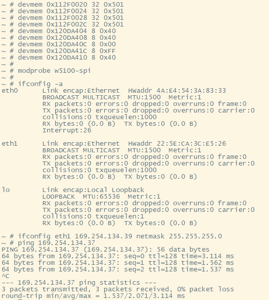
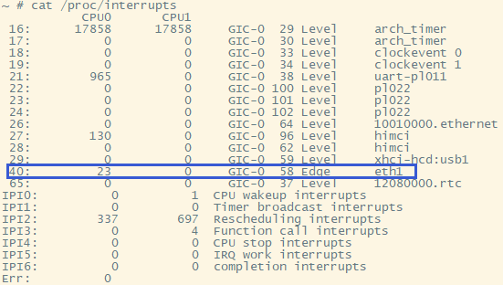
Executing cat /proc/interruptsthis command will allow you to view the interruptions registered for this device.
Then, tools such as ethtool and iperf3 can be used to view and test the device. The command to query network card information using ethtool is: [command to query network card information] ethtool -i eth1. The testing process using iperf3 is shown in the following figure:
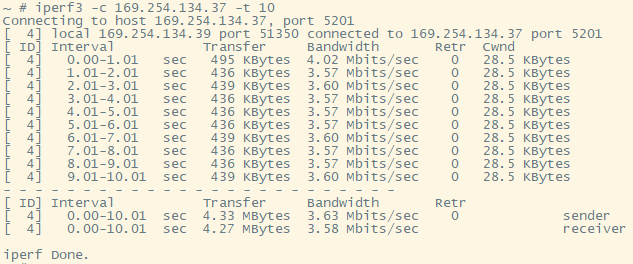
[Add ethtool and iperf3 to Buildroot] If you choose Buildroot to create the root filesystem, you can
menuconfigadd the ethtool and iperf3 packages before compiling Buildroot:
- Target packages -> Networking applications
- Select ethtool
- Select iperf3
7.1.3 Existing Problems
There are two problems with using the W5500 on the Hi3516DV300:
(1) Interrupt number allocation problem
As mentioned earlier, to ensure the W5500 driver can correctly acquire interrupt numbers, we disabled all GPIO drivers in the kernel, preventing users from using user-mode GPIO devices. Even request_threaded_irq()adding IRQF_SHAREDa flag to the interrupt request function parameters in the W5500 driver cannot share interrupts with GPIO, and the following message will still be displayed:
genirq: Flags mismatch irq 40. 00000088 (eth1) vs. 00000084 (120da000.gpio_chip)
w5100: probe of spi1.0 failed with error -16
(2) Send queue timeout
When using the iperf3 server on the development board and the iperf3 client on the PC for throughput testing, the following transmit queue 0 timed outerror may be triggered:
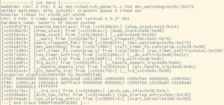
This error causes delays in data transmission and reception, or even prevents communication altogether, but it remains unresolved.
7.2 Using the USB Gadget composite driver for serial and network communication with a PC
The kernel configuration provided by the SDK already enables support for the RNDIS + CDC Serial + Storage configuration USB Gadget composite driver. Simply change the USB controller to device mode to use it. The relevant configuration items can be found in the kernel configuration interface under Device Drivers -> USB Support -> USB Gadget Support -> Multifunction Composite Gadget .
Use menuconfigthe configured kernel:
make ARCH=arm CROSS_COMPILE=arm-himix200-linux- menuconfigMake the following modifications:
- Device Drivers -> PHY Subsystem -> Hisilicon USB related configuration
- Cancel USB DRD0 Mode Select HOST
- Select USB DRD0 Mode.
Save and recompile the kernel, burn the generated uImage to the board, and copy the kernel module driver to the corresponding directory of the root file system as described above.
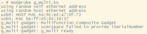
After booting into the system, you can execute the following command to mount the composite driver.
modprobe g_multi.ko[Important - Mount Command Explanation] In general, when mounting the g_multi driver, the mount path parameter used as g_mass_storage must be specified, as shown in section 6.3, "Connecting the Development Board Partition to the PC Using the USB Gadget ." However, actual testing revealed that for the Hi3516DV300, the g_multi driver cannot be recognized by the PC as a storage drive letter. This section will not delve into this issue, but will only describe how to use u_serial and RNDIS. Therefore, the path parameter is not added to the mount command above. Mounting u_serial and RNDIS can also be performed separately and independently, which will not be discussed here.
7.2.1 Usage of u_serial
Connect the development board to your PC, and you can see the recognized serial port in Device Manager:
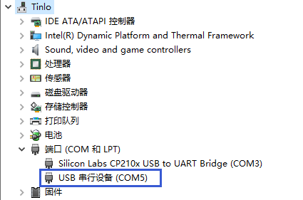
At this point, the ttyGS0 node should be automatically generated in the /dev/ directory of the development board system. If it is not automatically generated, you can use the command to view the device number of the device, and then use the command to create it yourself.cat /sys/class/tty/ttyGS0/devmknod
This serial port device allows the development board and PC to communicate, with a default baud rate of 115200. After configuration, the board's serial control console can be accessed from the PC via this port. Interested readers can find relevant materials for further study.
7.2.2 Use of RNDIS equipment
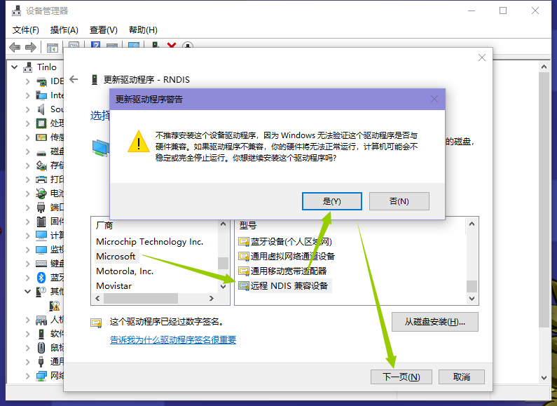
RNDIS recognizes the device as a network interface card (NIC). Connecting the development board to the PC allows you to see the recognized RNDIS device in Device Manager.

Right-click the device, select "Update driver" -> "Browse my computer for driver information" -> "Let me pick from a list of available drivers on my computer" -> "Network adapters" -> "Microsoft - Remote NDIS compatible device", select "Yes" in the pop-up warning, and then click "Next" to complete the installation.
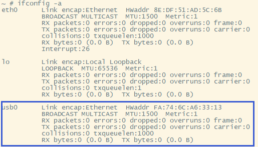
At this point, a network card device will be recognized on the PC:
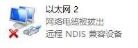
Corresponding to the USB0 network device node on the board:
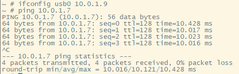
By configuring both devices to be on the same subnet, they can communicate with each other. This method can also be used to connect the development board to the external network, but this will not be discussed here; interested readers can find relevant information for further study.
The results of the network throughput test using iperf3 are as follows:
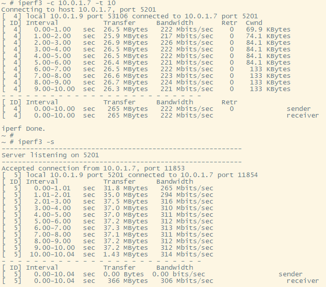
During testing, it was found that when the development board was the iperf3 client and the PC was the iperf3 server, the use of other USB devices on the PC was affected during the speed test, such as mouse lag; otherwise, there was no obvious adverse effect.
7.2.3 Existing Problems
(1) Support for mass_storage is invalid in the g_multi driver on Hi3516DV300.
See the composite driver mounting screenshot at the beginning of this section. The board-side printout does not show the log output of the mass_storage device, and the storage device is not recognized on the PC after the driver is mounted.
(2) Interference between USB devices during RNDIS testing
See section 7.2.2, "Use of RNDIS Devices," for details. It is currently unclear whether this behavior is normal.
8 Questions and Answers
No questions or submissions were received from the target audience during the writing of this document.
No FAQ document can cover all the issues; where there are people, there will be problems. But it is these problems that give "debugging" "meaning" and "experience" "value."
Too many details have been overlooked—we ultimately cannot grasp the full scope of embedded systems in such a short time, which is a regret. But so what? You've already embarked on this magnificent journey!
———— 2022-4-16 @YanWeibo ————
Copyright Notice: This article is contributed by internet users, and the views expressed are solely those of the author. This website only provides information storage space and does not own the copyright, nor does it assume any legal responsibility. If you find any content on this website that is suspected of infringement/illegal or irregular, please send an email to the reporting department. Once verified, this website will delete it immediately.
Posted by: Full-Stack Programmer (Stack Leader), please indicate the source when reprinting: https://javaforall.cn/190080.html Original link: https://javaforall.cn